行政院國家科學委員會專題研究計畫 成果報告
子計畫一:高階合成之形式驗證技術研究
計畫類別: 整合型計畫 計畫編號: NSC94-2220-E-009-039- 執行期間: 94 年 08 月 01 日至 95 年 07 月 31 日 執行單位: 國立交通大學電機與控制工程學系(所) 計畫主持人: 董蘭榮 計畫參與人員: 江宗錫, 楊學之, 張騰轟, 黃仕捷, 吳智偉, 呂文豪, 何峻 徹, 林耕興, 林盟淳, 賴信丞 報告類型: 完整報告 處理方式: 本計畫可公開查詢中 華 民 國 95 年 10 月 31 日
中英文摘要
(一) 計畫中文摘要 本計畫主要是研究探索用於高階合成之形式驗證技術,目的在於發展出利於 系統階層設計之形式驗證技術。近年來,形式驗證技術已被視為由上至下系 統晶片設計流程中重要的一環。目前已有不少研究文獻應用於邏輯階層或是 暫存器轉換階層的形式驗證技術,如:對等檢查與模型查證等。然而,很少 有研究著重於高階抽象階層之形式驗證技術,如:定理證明、性質證明、性 質涵蓋率、有利形式驗證等。基於此,本計畫將分成三階段探討形式驗證技 術,以利系統晶片之高階合成設計。首先,計畫將針對演算法架構實現發展 資料流定理證明技術。利用派屈網路作為驗證基底,對應架構實現時之排程 與配置達成定理證明之目的。而後,計畫焦點將擺在性質證明方面。從形式 驗證之性質描述出發,發展 出性質充分性量化技術,進而計算出性質涵蓋 率。主要目標是希望解決形式驗證令人議論之性質描述完整性問題。最後, 我們將以定理證明與性質證明之研究成果為基礎,發展出有利形式驗證設計 技術。有利形式驗證設計將幫助系統晶片設計者更易使用形式驗證來驗真設 計結果 關鍵詞: 系統晶片;形式驗證;定理證明;有利驗證設計 (二) 計畫英文摘要The System-On-Chip (SOC) design encompasses a large design space. Typically, the designer explores the possible architectures, selecting algorithms, choosing architectural elements, and constructing candidate architectures. Designing such a complex system is hard; designing such a system that will work correctly is even harder. Design errors should be removed as early as possible; otherwise, errors detected at the later stages will result a costly, time-consuming redesign cycles. Thus, the designer should face two distinct tasks in SOC design; carrying out design process itself and establishing the correctness of a design. Design correctness is the main theme of this project. This project aims on the formal verification for high-level synthesis and addresses on three issues: theorem proving, property reasoning, and design for formal verification. First of all, the project will develop theorem proving technique for architectural design. Based on Petri-Net models, the theorem proving
verifies the reachability, admissibility, and correctness of task scheduling and resource allocation. In the property reasoning, the project will focus on metrics of property coverage. With accurate calculation on property coverage, the notorious property-validation problem can be lessened or even solved. Finally, a technique on design-for-formal-verification (DFFV) will be developed, driven by theorem proving and property reasoning. The DFFV technique will aid SoC designers for efficiently applying formal verification in proof of their design.
目錄
中英文摘要 ………. I
目錄 ………. III
報告內容 ………. 1
一、
前言 ……… 1
二、
研究目的 ……… 2
三、
文獻探討 ……… 2
四、
研究方法 ……… 3
五、
結果與討論 ……… 4
參考文獻 ……… 23
計畫成果自評 ……… 25
報告內容
一、 前言 目前積體電路設計的主要趨勢之一是以系統晶片(System-on-Chip)來實現複雜的系統。通 常,實現目標系統的過程分兩方面,一方面要整合多個智財(IP)單元於單一的系統晶片上,另 一方面要驗證設計結果以符合系統要求。要成功的整合數個智財單元於單一的系統晶片上要達 成下列三項目標: 選定符合不同即時要求的系統晶片組織、正確地在選定的架構上實現應用並 驗證之、經濟快速地完成系統晶片合成與模擬。欲達成這些目標,必須發展一套由上而下的階 層式設計流程。設計者先在不同的象徵層次上產生設計結果,而後在進入下一個層次之前先確 認設計結果的正確與否。其中,演算法發展、工作配置、組織設定三步驟建構成組織探索階層。 每一個步驟所產生的不適當設計結果將循再設計週期重回上一步驟。要如何有效率的確認設計 結果是否適當及正確便成為不可忽視的重要課題。目前,學術與產業界對於組織探索部分投入 不少心力,各步驟皆有不錯的研發成果。然而,這些研究成果對於驗證技術卻著墨不多且缺乏 整體的考量。不少的設計錯誤往往在執行較晚的設計步驟時發現,這些不能及早發現的錯誤將 造成設計成本的大幅提高。更有甚者,在組織探索階段無法偵測到的錯誤將使設計者在軟硬體 共發展階段付出更多的代價。圖一所示為典型的設計流程,設計者先在不同的象徵層次上產生 設計結果,而後在進入下一個層次之前先確認設計結果的正確與否。 Architecture Exploration Architectural Specification Field prototyping (off-cycle update) HW/SW co-development Task Allocation(Partitioning, Assignment, Scheduling) Algorithm
Development Requirements
Reuse COTS Library and
Interoperable Package
Reuse COTS Library and
Interoperable Package (off-cycle update)
redesign path
圖一:系統晶片設計流程
的不適當設計結果將循再設計週期重回上一步驟。要如何有效率的確認設計結果是否適當及正 確便成為不可忽視的重要課題。目前,學術與產業界對於組織探索部分投入不少心力,各步驟 皆有不錯的研發成果。然而,這些研究成果對於驗證技術卻著墨不多且缺乏整體的考量。不少 的設計錯誤往往在執行較晚的設計步驟時發現,這些不能及早發現的錯誤將造成設計成本的大 幅提高。更有甚者,在組織探索階段無法偵測到的錯誤將使設計者在軟硬體共發展階段付出更 多的代價。 二、 研究目的 系統晶片設計涵蓋很廣的設計空間。設計者通常需要考量許多可能的系統組織包括選擇 演算法則、挑選組織元件、建構候選組織。設計如此的複雜系統誠屬不易,而要設計出 能完全符合要求、正確無誤的系統更為困難。設計上的失誤必須要儘早排除,否則在後 續階段才發現的失誤將造成耗費耗時的再設計周期。因此,設計者必須面對兩項課題, 其一是實現設計程序本身、另一是建立正確的設計結果。其中,設計的正確性將為本計 劃的主軸。鑑於此,本計畫以開發出系統晶片高階合成之形式驗證技術為目標。 三、 文獻探討 近年來,形式驗證技術已被視為由上至下系統晶片設計流程中重要的一環[1]-[3]。目 前已有不少研究文獻應用於邏輯階層或是暫存器轉換階層的形式驗證技術,如:對等檢查 (Equivalent Checking[4]-[15]與模型檢查(Model Checking) [16]-[20]等。然而,很少 有研究著重於高階抽象階層之形式驗證技術,如:定理證明(Theorem Proving)、性質證明 (Property Reasoning)、性質涵蓋率(Property Coverage)、有利形式驗證(Design for Formal Verification)等。圖二為形式驗證之完整流程。完整之形式驗證流程通常應搭配不同設計階 段進行驗證。在演算法發展時,合理查證便開始驗真(Validate)演算法之正確性。合理查證 的工具為數學論證,如遞迴法。進入高階合成階段,定理證明將開始檢查軟硬體組織基本 特 性 與 演 算 法 之 一 致 性 , 如 死 結 (deadlock) 、 資 料 關 聯 (data dependency) 、 可 達 成 性 (reachability)等。而後再進行性質查驗(Property Checking)。利用 CTL 或 LTL 等時序邏輯查 驗軟硬體交握時之邏輯正確。最後在邏輯合成階段,模型檢查與對等檢查將分別進行 RTL
FSM 與 Kripke 模型間之驗證以及邏輯電路與 RTL 間的對等性檢查。 Reasoning About Theorem Proving Property Checking Modeling Checking Equivalent Checking Algorithm Development High-Level Synthesis Logic Synthesis 圖二:形式驗證流程 過去十年,國內外的研究對於邏輯合成階段已有不錯的研究成果[5]-[20]。不少文獻發表完整 的解決方案。目前大部分的研究著重於降低形式驗證複雜度與新式的 RTL 描述規範。至於高階 合成的研究較少著墨。相關的研究主要著眼於性質證明與性質涵蓋率[21]-[26]。因為形式驗 證最易引起質疑的部份就是性質描述之適當性與充分性。如何判斷所定義出之性質足夠驗 證出潛在的設計錯誤將影響形式驗證的成敗。
例如,要驗證匯流排設計上 Acknowledge 與 Request 間的協定,可以簡單的利用”Req→Ack” 來描述性質。然而此一描述將視”Two acknowledges after one request”之動作視為正確。這代 表”Req→Ack” 是一個有缺陷的描述。不幸的是這樣的缺陷描述很易於發生在一般設計者 描述形式驗證性質時。來自以色列西伯萊大學之 Dr. Chockler 是少數的先驅之一。她提出 易位法找出性質描述的涵蓋率,進一步證明性質的充分性。然而,易位法所需的運算複雜 度是 O(2N )。未來性質描述之適當性與充分性還有很大的進步空間。 四、 研究方法 本計畫將分成三階段探討形式驗證技術,以利系統晶片之高階合成設計。首先,計畫 將針對演算法架構實現發展資料流定理證明技術。利用派屈網路(Petri-Net Model)作為驗證 基底,對應架構實現時之排程與配置達成定理證明之目的。而後,計畫焦點將擺在性質證 明方面。從形式驗證之性質描述出發,發展出性質充分性量化技術,進而計算出性質涵蓋 率。主要目標是希望解決形式驗證令人議論之性質描述完整性問題。最後,我們將以定理
證 明 與 性 質 證 明 之 研 究 成 果 為 基 礎 , 發 展 出 有 利 形 式 驗 證 設 計 (Design-for-Formal-Verification)技術。有利形式驗證設計將幫助系統晶片設計者更易使用形 式驗證來驗真設計結果。 計畫第一年將發展資料流定理證明技術。首先,我們將轉換演算法結果成派屈網路模型 以保留資料流特質。利用派屈網路模型的定理,發展出形式驗證所需之定理描述(Theorem Specification)。而後再發展出定理證明環境,同時檢查組織架構之靜態排程與動態運行是 否 符 合 資 料 流 基 本 定 理 , 如 死 結 (deadlock) 、 資 料 關 聯 (data dependency) 、 可 達 成 性 (reachability)等。 第二年我們將開始性質證明與充分性研究。首先將性質的合理程度量化,簡化性質涵蓋率 之計算。我們將再利用派屈網路模型與有限狀態機(FSM),發展出適切的 Kripke 模型對應。 找出設計變異可能集合與集合元素之重複性,再進一步縮減集合大小達成簡化性質涵蓋率 計算的目的。利用性質涵蓋率計算,我們將有機會找出能補足性質缺陷的驗證流程。這個流程 將半自動或全自動地逐步加強性質描述,以完成高可靠度的形式驗證。 計畫的最後一年將利用既有成果發展對形式驗證友善之高階合成技術。基於對性質證 明與充分性研究的參透,我們將從高階合成之合法解中選出抗性質缺陷的結果。如此一來, 形 式 驗 證 將 更 易 於 使 用 且 可 靠 。 據 此 , 我 們 將 提 出 有 利 形 式 驗 證 設 計 技 術 。 Design-for-Formal-Verification 將可成為單晶片系統設計的重要一環,並解決由上至下 流程之複雜驗證問題。 五、 結果與討論 今年度本計畫共產出下列一篇期刊論文與一篇會議論文:
1. Tsung-His Chiang and Lan-Rong Dung, 2006, June, “System Level Verification on High-Level Synthesis of Dataflow Algorithms Using Petri Net,” WSEAS transactions on Circuits and Systems, Issue 6, Vol. 5, pp.790-796
2. Tsung-Hsi Chiang, and Lan-Rong Dung, “System-Level Verification on High-Level Synthesis of Dataflow Graph,” ISCAS 2006.
System Level Verification on High-Level Synthesis of Dataflow
Algorithms Using Petri Net
Tsung-Hsi Chiang & Lan-Rong Dung Department of Electrical and Control Engineering
National Chiao Tung University 300, Hsinchu City
Taiwan, R.O.C. [email protected]
Abstract: - This paper presents a formal verification algorithm using the Petri Net theory to detect design errors
for high-level synthesis of dataflow algorithms. Typically, given a dataflow algorithm and a set of architectural constraints, the high-level synthesis per-forms algorithmic transformation and produces the optimal scheduling. How to verify the correctness of high-level synthesis becomes a key issue before mapping the synthesis results onto a silicon. Many tools exist for RTL design, but few for high-level synthesis. Instead of applying boolean algebra, this paper adopts the Petri Net (PN) theory to verify the correctness of the synthesis result, because the Petri Net model has the nature of dataflow algorithms. Herein, we propose two approaches to realize the PN-based formal verification algorithm and conclude the best one who outperforms the others in terms of processing speed and resource usage.
1 Introduction
With increasing design complexity of digital signal processing system, verification becomes a more and more important within the design flow. In modern circuits, it is observed that up to 80% of the overall design costs are due to verification. Formal verification techniques which ensure 100% coverage of function and system model correctness have gained large attention. In [1,2], authors give excellent survey of major trends of formal verification techniques which can be classified into two categories, equivalence checking [2] and model checking [3]. Equivalence checking is used to proof the functional equivalence of two design representations modeled at the same or different levels of abstraction. Model checking is a process that checks the correctness of a design model with given properties. Although formal verification for logic synthesis has been studied very extensively, little work has been done for high-level synthesis.
This paper presents a novel verification algorithm to verify high-level synthesis (HLS) of dataflow algorithms. Given a dataflow graph (DFG) and architectural constraints, the HLS aims to generate the task schedule with processor assignment. Typically, the HLS performs algorithmic transformation, such as retiming, scaling, and unfolding, on the DFG to meet the architectural constraints, and allocates resources accordingly [4,5,6,7,8]. Both algorithmic transformation and resource allocation require complex procedures. These procedures are rather heuristic and error-prone. The integer linear programming (ILP), for instance, is one of the popular techniques applied for HLS. The success of ILP is relied on the completeness of clauses. Any mistake or incomplete description made in the ILP may result in an illegal solution and screw up following synthesis results. This paper intends to present a formal verification algorithm to unveil the faults produced in HLS.
In the proposed algorithm, we employed the Petri-Net model as the formal description to check the correctness of dataflow behavior. Petri Net model has the nature of dataflow computing, and hence a good tool for the verification of algorithmic transformations and datapath scheduling. The use of the Petri-Net is two-folded. First, the Petri-Net model of dataflow algorithm can hold the data dependence and hence any legal transformation has to conform to the firing rules of the Petri-Net model. Secondly, the scheduling candidate is correct if and only if the initiation of each task is allowed in the Petri-Net model. Comparing with the traditional model checking techniques, the first use can provide simple but thorough model for restructured algorithms while the second use can avoid false negative problems.
The inputs to the proposed formal verification are the system description and task schedule. The system description is basically a fully-specified flow graph (FSFG) [9].
The FSFG represents the behavioral specification of the dataflow algorithm which is also a design entry of HLS. In HLS, to meet the architectural constraints, the algorithmic transformation normally reconstructs the initial FSFG to find out optimal scheduling results. The reconstructed FSFG is admissible if and only if it is equivalent to the initial FSFG. To verify the correctness of the task schedule, the proposed algorithm first converts the initial FSFG to a Petri-Net model which is expressed by Petri-Net characteristic matrix, because any admissible reconstructed FSFG has to have the same characteristic matrix.
Another input is the schedule, the DUV (design under verification), generated by HLS. The schedule is expressed in the format of processor-time chart (or chart). The chart equally shows the firing sequence. The proposed verification uses the firing sequence to unveil the legal algorithmic transformations applied for the original FSFG. The legal algorithmic transformations will then be candidates to trace the firing sequence of the given schedule.
Based on the inputs, the proposed verification first extracts the initial firing pattern and uses it to determine the candidate reconstructed FSFGs. The candidates will then be verified with the Petri-Net model. If there exist at least one candidate who can allow the firing sequence to execute legally (without against the firing rules), the HLS result is claimed as a correct solution; otherwise, the verification will show the counter example in proof of the incorrectness. In this paper, we propose two approaches to realize the PN-based formal verification and conclude the best one who outperforms the others in terms of processing speed and resource usage.
The remainder of this paper is organized as follows. Section 2 describes some useful definition and proposed modeling technique. The proposed high-level verification technique and verification algorithms are presented in section 3. In section 4, we discuss the complexity analysis of two verification algorithms. In section 5 some experimental results are given. Section 6 gives the conclusions of this paper.
2 Definition and Modeling
In this section, we will discuss some useful definitions and proposed transformation technique to transform a FSFG into PN model.
2.1 Fully-Specified Signal Flow Graph
Fully-Specified Signal Flow Graph (FSFG) [9] or DFG is a natural paradigm for describing DSP algorithms. A FSFG GFSFG(V,E,D), where V={v1,…,vn} and
E={e1,…,em}, is a three-tuple directed and edge-weighted graph which contains a
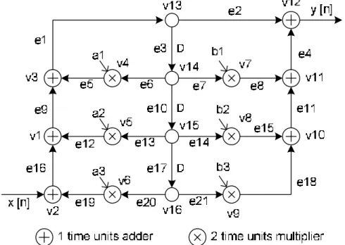
atomic operation of functional units. A vertex may have a zero execution delay, such as the signal duplicator, or may be assumed to take non-zero unit time, such as adder or multiplier. Directed edge set E describes the direction of flow of data between functional units. Inter data dependencies between functional units are denoted by weighted edges. Figure 1, for instance, shows a third-order IIR filter in the form of FSFG.
Fig. 1. A third-order IIR filter in the form of FSFG.
2.2 Petri Net Model
A Petri Net GPN(P,T,W,M) is a four-tuple [10], where P={p1,…,pn} and T={t1,…,tm} are
finite sets of place and transition, W is the weighted flow relation, and M0 is the initial
marking. A marking is a function M:P→Z. If M(pZ i)=k for place pi, we will say that pi
is marked with k tokens. If W(u,v)>0, then there is an arc from u to v with weight
W(u,v). Usually, matrix representation gives a complete characterization of Petri Net.
The characteristic matrix of PN is defined by incidence matrix A, which is a |P|×|T|-matrix with entries
ij j i i j
A =W tr p , −W p tr , (2)
Marking m0 is an |P|×1 column vector with entities m0(i)=M(pi), ∀pi ∈P. We say that
is a valid marking if and only if m0(pi)≥0. Let xj={trj}=(…,0,1,0,…) be the unit |T|×1
column vector, which is zero everywhere except in the j-th element. Transition tj can
be represented by the column vector xj. We say that tj is enabled at a marking m0 if
m0≥A⋅xi for every element of m0 is a non-negative integer. And the result m′ of firing
0 j
m′ =m + ⋅A x (3)
2.3 Transformation from FSFG to PN
The FSFG is attractive to algorithm developers because it directly models the equations of DSP algorithm. Yet, it does not sufficiently unveil the dynamical behaviour and the implementation limits in terms of the degree of parallelism and the memory requirement. Thus, we use Petri Net to model DSP algorithms. It also allows us to discover the characteristic of the target architecture and to observe the dynamical behaviour of the algorithm.
The FSFG GFSFG(V,E,D) of a DSP algorithm can be modelled as PN GPN(P,T,W,M0)
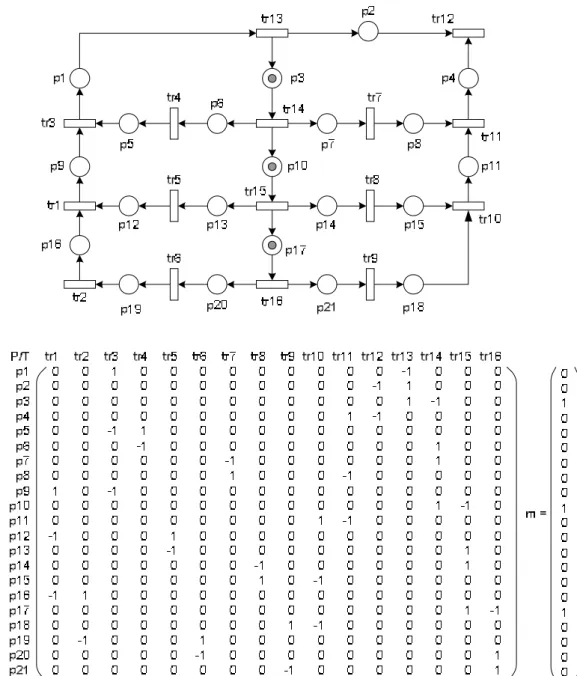
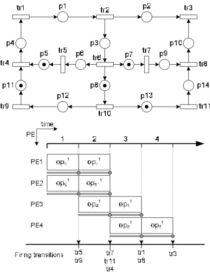
by applying following rules. First, functional element set V and edge E of FSFG can be transformed into the transition set T and the place P with respect. Since, each place in PN has only one output, the pseudo transition of each fork edge will be added as source duplicators. At last, the delay element set D of edge in FSFG is corresponded to the number of tokens of place in PN. By applying above transition rules, an example in Figure 2 shows the PN model of the third-order IIR filter in Figure 1. The characteristic matrix A with the initial marking m shows the matrix representation of the PN model, for instance.
Fig. 2. A PN graph and the matrix representation to the third-order IIR filter of
Figure 1.
2.4 Schedules to the FSFG
In HLS, a FSFG design may contain cycles to model a DSP application with loops. The intra-iteration precedence relation is represented by the edge without delay and the inter-iteration precedence relation is represented by the edge with delays. Given an edge e(vi,vj)∈E in FSFG design, d(e) means the data used as inputs in node vj are
generated by node vi at d(e) inter-iteration before. A static schedule of a cycle FSFG is
a repeated pattern of an execution of the corresponding loop. And a static schedule must obey the precedence relations of the directed acyclic graph (DAG) portion of a FSFG design that is obtained by removing all edges with delays from that FSFG.
Let dji be the execution delay for each task node opji, the length le(S) of a schedule
S is the latest finish time of all the operations scheduled, that is
le(S)=max{ϕ(opji)+dji-1|∀ opji∈V}. For each task node opji∈V, a schedule of the
FSFG design is given as following:
■ Start time: i i {1 2 } j j t =ϕop , : → Ζ = , ,Kϕ V + ■ Execution delay: i {0 1 2 } j d ∈ Ζ = , , ,K ■ Finish time: i i i 1 j opj dj ε ϕ = + − ■ Task assignment: i ( i) {1 2 } j j res pe =τ op , : → , , ,τ V K n
■ Length of the schedule:
{
}
( ) max i i 1 | i
j j j
le S = ϕop +d − ∀op ∈V
■ The earliest task-finished step:
{
}
min i i 1 | i
etf j j j
t = ϕop +d − ∀op ∈V
3 High-Level Verification
In this section, proposed two-stage verification technique is introduced. The algorithms to both stages are also presented separately as the implementations.
3.1 Verification Flow
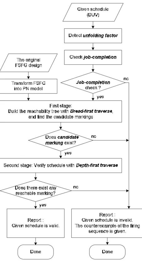
A flowchart illustrating our verification flow is shown in Figure 3. There are two inputs to the flow: a given schedule and the original FSFG. The given schedule is the DUV (design under verification) that needs to be verified. The original FSFG reserves the characteristics of the system that the DUV must be satisfied. The proposed verification method tries to find the correct restructured FSFG, which is candidate to the DUV at the first stage, and then, it checks whether the execution sequence, the DUV, of the PN model corresponded to the candidate is satisfied at the second stage. Before introducing two-stage verification method, we address the preprocessing on both inputs separately.
One of the inputs is the given schedule. In system-level design flow, designers may use unfolding algorithm to pursue perfect FSFG achieving iteration period bound on their original FSFG design. Usually, the FSFG of the DSP algorithm describes one iteration of the computation. By applying unfolding algorithm on the FSFG is to unfold the original FSFG by a factor f which implies f consecutive iterations of
the design. In contrast, we perform unfolding checking in our verification flow to detect the unfolding factor f from given schedule. Another input to the verification flow is the original FSFG graph. It is transformed into a PN model by proposed transformation rules.
In PN domain, the markings, which can be reached from the initial marking, can be seen as the retimed FSFGs of the original design. Some reachable markings are the correct restructured FSFGs for the given schedule. These markings, which dominate the correctness of the given schedule, are said to be the candidate markings. In order to find the candidate markings, Breadth-First algorithm is used to traverse all the markings of PN reachability tree at the first stage. If the candidate marking does not exist, it means the correct retimed FSFG does not exist, it reports the given schedule is not valid due to absent of the candidate marking. If the candidate marking exists, we continuously apply Depth-First algorithm on each candidate marking.
Fig. 3. Flowchart for the proposed high-level verification method.
The given schedule is valid if there exists an initial marking, the candidate marking, of the PN model leading a firing sequence of the schedule valid. At the second state, we apply Depth-First traverse procedure on each candidate marking to check whether the given schedule is valid by checking the firing sequence of the
schedule. At last, if it exists such candidate marking, the flow is done and reports given schedule is valid, or a counterexample of invalid firing sequence is reported if given schedule is invalid.
3.2 The Candidate Marking
The candidate marking set is a subset of the reachable marking set of a Petri Net. A candidate marking is probably the correct initial marking, it also means correct retimed FSFG, which leads the firing sequence of a given schedule being valid. Let S be a schedule of a FSFG. The earliest task-finished set etf_set of S are the tasks which are finished at the earliest task-finished step tetf in S, such that
{
ij| ij etf ij}
etf_set= op ε = , ∀t op ∈ .V (4)
Marking m is defined as a candidate marking, if marking m and firing sequence σ satisfies Definition 1.
Definition 1 Marking m is said to be a candidate marking if and only if there exists
a firing sequence σ:tr1…trk, such that for all tasks op∈etf_set are covered by all the
transitions in σ, i.e. etf_set⊆σ. And it is also satisfied that each firing transition trj∈σ
is either a pseudo transition, dj=0, or an earliest task-finished transition, εj=tetf.
Fig. 5. An example schedule and 2nd order IIR filter.
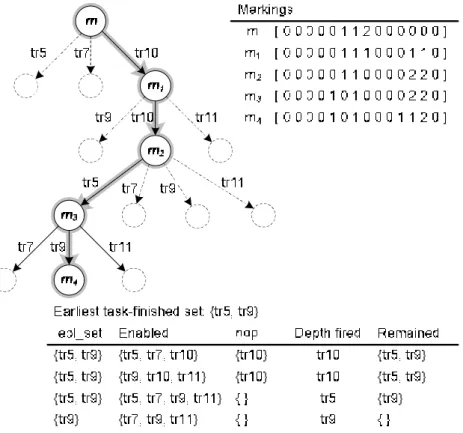
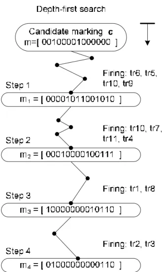
As an example, Figure 4 shows the procedure to check whether a marking is candidate. For a given schedule in Figure 5, the earliest task-finished step is tetf=1, and
the earliest task-finished set is etf_set={opji|εji=tetf=1}={v5,v9}. Marking m = [ 0 0 0 0
0 1 1 2 0 0 0 0 0 0 ] is said to be a candidate marking of the corresponded PN model.
Since, there exists a firing sequence σ:tr10 tr10 tr5 tr9, m m4
σ
→ , such that etf_set⊆σ. The markings, m1…mk, of the firing sequence, m→tr10m1→tr10m2→tr5m3→tr9 m4, are valid states.
3.3 Marking sets
The proposed high-level verification method includes two stages: the Breadth-First and the Depth-First traverse procedures. At the first stage, the Breadth-First traverse procedure tries to find candidate markings, the correct retimed FSFGs, from reachability tree. At the second stage, the Depth-First traverse procedure verifies given schedule by checking the candidate markings. Since, the nodes of reachability tree are exponential growth with the height of the tree, two-stage method is the better
policy. The verification method shortens the searching space by finding candidate markings at the first stage. At the second stage, it verifies given schedule by checking candidate markings rather than all the reachable markings of reachability tree.
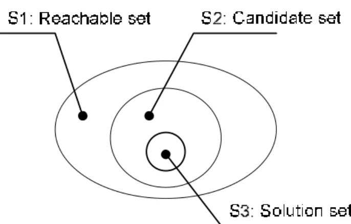
Fig. 6. The relation between reachable, candidate and solution marking sets.
Assuming there are n operations in a given FSFG, and hence there are n transitions in the corresponded PN model. Let f be the unfolding factor of a given schedule while designers performing unfolding technique on their FSFG design. At the first stage, the procedure tries to find the candidate marking set from the reachable marking set from the reachability tree and fires each transition once each time. The height of each marking in reachability tree is the distance from the root node to itself. Since, during one iteration period of the schedule S, le(S), each scheduled task must be fired once, the height can also be seen as the number of transitions that have been fired since the root node. Thus, for an n-tasks schedule, the upper height-bound of the reachability tree is bounded by Hup=f⋅n. At the second stage, it continually finds the solution
marking set from the candidate marking set. The set relation between three marking sets is shown in Figure 6, that is S3⊆S2⊆S1. The purpose of the first stage is trying to
reduce the searching space from reachable marking set S1 to candidate marking set S2, while the second stage is trying to find solution marking set S3 from candidate marking set S2.
3.4 First stage: Breadth-First Traverse
At the first stage of the verification method, we apply Breadth-First traverse procedure to find the candidate markings from the reachability tree. Two approaches, which include the early-terminated and the optimal approaches, are proposed in this paper and discussed in the following sections.
3.4.1 The early-terminated approach
early-terminated approach which improves the exhaustive approach. Before introducing the improved approach, we first consider Lemma 1.
Lemma 1 Let Ttree be a reachability tree which is bounded by upper height-bound
Hup and m1 be any one of the candidate markings in Ttree. For any other candidate
marking m2 in the successor path of marking m1, m2 is in the solution marking set S3
if and only if m1 is in S3.
Fig.8. The traverse order of early-terminated approach.
The early-terminated approach uses Lemma 1. It tries to minimize the size of candidate set S2 from reachable set S1. The difference between the exhaustive and the early-terminated approaches is that when an enqueued unvisited marking is candidate, the early-terminated approach ignores the candidate marking and marks as a visited node. Then, it proceeds other unvisited nodes in queue Q until all the markings have been visited. In Figure 8, as an example, the traverse order of the early-terminated approach is m, m1, m2, m3, …, m10.
3.4.2 The optimal approach
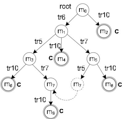
The second approach to verify a schedule of a given FSFG is the optimal approach which is improved from the early-terminated approach. In order to reduce reachable marking set S1 of the reachability tree, it tries to merge the redundant nodes when it proceeds Breadth-First traverse.
Let m be an unvisited node to be processed. If m is a candidate marking, it ignores this node by using Lemma 1 and proceeds other unvisited nodes in queue. If m is not a candidate marking, it applies negative test to find enabled set of transitions and
creates new node on each enabled transition. For each new produced node with marking m′, if there exists another node in the reachability tree, and has the same marking associated with it, then the node with marking m′ is a duplicate node. Since, the marking m′ has appeared in the tree, this new produced node is redundant. Then, it merges this redundant node to the existential node and creates transition link from marking m to the existential node. As an example in Figure 9, when it proceeds marking m5, it founds the new created node with marking m7 is a duplicate node. It
merges these nodes and creates transition from m5 to m7. Then, it continually proceeds
other unvisited nodes in queue.
Fig. 9. Merge the redundant node in optimal traverse approach.
3.5 Second stage: Depth-First traverse method
At the second stage, we apply Depth-First traverse procedure to verify a schedule on candidate markings rather than all reachable markings in PN model. As showing in Figure 10, a candidate marking m which is found in the first stage is probably the correct marking, the correct retimed FSFG that leads a given schedule being valid. For a given schedule in Figure 5, task tr5 and task tr9 are scheduled and finished at the
first step of the schedule. The procedure tries to fire one transition of these scheduled tasks or enabled nop operations once each time during the first scheduled step. At the end of the first step, marking m1 is obtained from candidate marking m by firing
transition sequence σ:tr6 tr5 tr10 tr9, that is m m1
σ
→ , where transition tr6 and tr10 are nop
step-by-step until all the scheduled tasks are fired. A given schedule is said to be valid if and only if all the markings in the traverse path are valid.
4 The Complexity Analysis
Assuming there are n non-nop operations in a given FSFG. Let f be the unfolding
factor of a given schedule. As described in previous section, the upper-height of the
reachability tree of the corresponded PN model is bounded by Hup= ×f n. The complexity analysis of the proposed two-stage verification method is discussed as following.
At the first stage, two approaches are proposed including the early-terminated and the optimal traverse methods. Considering each node in the reachability tree has n enabled transitions in worse case, the level 0 (the root node) has one node.
Level 1 has n nodes
Level 2 has (n)(n)=n2 nodes
……
Level f×n has (nf⋅n-1)(n)=n f⋅n nodes The total number of nodes is:
(
)
( )2 1
1 f n f n 1 1
n n n ⋅ n ⋅ + n
Fig. 10. Verify schedule with Depth-First search algorithm
In the first approach, the early-terminated approach, the algorithm stops traversing a node while it is candidate. Let p, p≤(f n⋅ ), be the deepest level that Breadth-First traverse procedure can reach. The complexity of the second approach is
( p)
O N , ≤ ⋅p f n.
In the second approach, the optimal approach, the algorithm merges duplicate markings in order to reduce the reachable marking set of the reachability tree. Let
{1 2 }
x∈ = , ,Z L be the merging radio in the reachability tree. The complexity of the three approach is (( ) )p
O N x/ , ≤ ⋅p f n. Thus, the relation of the complexity between two
approaches is: ( )
(
p)
p
O N >O N x/ . (6)
At the second stage, the algorithm performs Depth-First traverse to verify a given schedule by checking the firing sequence, which contains f n⋅ transitions , of the PN model. Thus, the complexity is O f n( ⋅ ), in worse case.
5 Experimental Results
We have implemented these three approaches as the proposed formal verification algorithms. Each of these approaches is applied to several dataflow algorithms. Figure 11 shows the statistics of these designs.
Fig. 11. The statistics of test designs
Fig. 12. The experimental results
Design iir2d-sch1 to iir2d-sch4 and design iir3d-sch1 to iir3d-sch1 [9] are the second-order and the third-order Infinite Impulse Response filters. Design p243 [9] is a design with unfolding factor 6, the lengths of schedule p243-sch1 and p243-sch2 are both 96 steps. Design ewf-sch1 and ewf-sch2 are low power schedules for the Elliptic Wave Filter in [5]. Figure 12 shows the experimental results of using three approaches. The optimal approach outperforms the others in terms of time and resource usage.
6 Conclusion
This paper aims to exploit formal verification techniques for high-level synthesis. In the top-down design flow, design errors should be removed as early as possible; otherwise, errors detected at the later stages will result a costly, time-consuming redesign cycles. Although formal verification for logic synthesis has been studied very extensively, little work has been done for high-level synthesis. The paper presents a novel verification flow that can efficiently detect the design errors from the results of high-level synthesis. As shown in the experimental results, we can apply the optimal approach for the first phase to efficiently verify complex design cases.
References:
[1] A. Gupta, “Formal hardware verification methods: a survey,” Formal Methods in
System Design, vol. 1, pp. 151–238, 1992.
[2] C. Kern and M. Greenstreet, “Formal verification in hardware design: a survey,”
ACM Transactions on Design Automation of E. Systems, vol. 4, pp. 123–193, Apr.
1999.
[3] E. M. Clarke, O. Grumberg, and D. A. Peled, Model checking, The MIT Press, 1999.
[4] V. K. Madisetti and B. A. Curtis, “A uantitative methodology for rapid prototyping and high-level synthesis of signal processing algorithms,” IEEE
Transactions on signal processing, vol. 32, no. 11, pp. 3188–23 208,Nov.1994.
[5] L.-R. Dung and H.-C. Yang, “On multiple-voltage high-level synthesis using algorithmic transformations,” IEICE Transactions on Fundamentals, 2004. [6] K. Ito, L. E. Lucke, and K. K. Parhi, “Ilp-based cost-optimal dsp synthesis with
module selection and data format conversion,” IEEE Transactions on Very Large
Integration Systems, vol. 6, no. 4, pp. 582–594, Dec. 1998.
[7] K. K. Parhi, “High-level algorithm and architecture transformations for dsp synthesis,” Journal of VLSI signal processing, vol. 9, pp. 121–143, 1995.
[8] L.-F. Chao and E. H.-M. Sha, “Scheduling data-flow graphs via retiming and unfolding,” IEEE Transactions on parallel and distributed systems, vol. 8, no. 12, pp. 1259–1267, Dec. 1997.
[9] V. K. Madisetti, VLSI Digital Signal Processors, IEEE Press, 1995.
[10] W. Reisig and G. Rozenberg, Lectures on Petri Nets I: Basic Models Springer-Verlag, 1998.
[11] K. Parhi and D. Messerschmitt, “Static rate-optimal scheduling of iterative data-flow programs via optimum unfolding,” IEEE Transactions on Computers, vol. 40, no. 2, pp. 178–195, Feb. 1991.
[12] C. Hwang, J. Lee, and Y. Hsu, “A formal approach to the scheduling problem in high level synthesis,” IEEE Trans. Computer-Aided Design of Integrated Circuits
參考文獻
[1] R. E. Bryant, “Graph-Based Algorithms for Boolean Function Manipulation”, IEEE Trans. on Computers, vol. C-35, Aug. 1986, pp. 677-691.
[2] E.M. Clark, O. Grumberg, and D. Peled, “Model Checking”, The MIT Press, 2000
[3] S.-Y. Huang and K.-T. Cheng, “Formal Equivalence Checking and Design Debugging,” Kluwer Academic Publishers, 1998
[4] C.L. Berman and L.H. Trevillyan,” Functional comparison of logic designs for VLSI circuits ,” ICCAD ‘89, pp.456-459
[5] E.I. Goldberg, M.R. Prasad, and R.K. Brayton, "Using SAT for combinational equivalence checking," DATE 2001, pp.114-121
[6] J.-H.R. Jiang, J.-H.R. and R.K. Brayton, "On the verification of sequential equivalence," IEEE Transactions on Computer-Aided Design of Integrated Circuits and Systems, Vol.22, No.6 , June 2003, pp.686-697
[7] Shi-Yu Huang, Kwang-Ting Cheng, Kuang-Chien Chen, Chung-Yang Huang, and F. Brewer, "AQUILA: an equivalence checking system for large sequential designs," IEEE Transactions on Computer, Vol.49, No.5, May 2000, pp.443-464
[8] S. Reda, A. Wahba, A. Salem, D. Borrione, M. Ghonaimy, "On the use of don't cares during symbolic reachability analysis," ISCAS 2001, pp.121-124
[9] S. Reda, A. Wahba, A. Salem, "M-CHECK: a multiple engine combinational equivalence checker," ISCAS 2000, pp.613-616
[10] Jha, Y. Lu, M. Minea, E.M. Clarke, E.M., "Equivalence checking using abstract BDDs," ICCD '97, pp.332-337
[11] Hee Hwan Kwak, In-Ho Moon, J.H. Kukula, T.R. Shiple, T.R., "Combinational equivalence checking through function transformation," ICCAD 2002, pp.526-533
[12] P. F. Williams, H. Hulgaard, H. Andersen, "Equivalence checking of hierarchical combinational circuits," ICECS '99, pp.355-360
[13] J. Marques-Silva, T. Glass, "Combinational equivalence checking using satisfiability and recursive learning," DATE 1999, pp.145-149
[14] A. Gupta, P. Ashar, "Integrating a Boolean satisfiability checker and BDDs for combinational equivalence checking," Eleventh International Conference on VLSI Design, 1998, pp. 222-225
[15] P. Ashar, A. Ghosh, S. Devadas, "Boolean satisfiability and equivalence checking using general binary decision diagrams," ICCD '91, pp.259-264 [16] A. Biere, A. Cimatti, E.M. Clarke, M. Fujita, Y. Zhu, "Symbolic model
checking using SAT procedures instead of BDDs," DAC 1999, pp.317-320 [17] N. Saxena, J. Baumgartner, A. Saha, J. Abraham, "To model check or not to
model check," ICCD '98, pp.314-320
[18] G. Parthasarathy, M.K. Iyer, K.-T. Cheng, L.-C. Wang, "Safety property verification using sequential SAT and bounded model checking," IEEE Design & Test of Computers, Vol.21, NO.2, pp.132-143
[19] P. Dasgupta, J.K. Deka, P.P. Chakrabarti, "Model checking on timed-event structures," IEEE Transactions on Computer-Aided Design of Integrated Circuits and Systems, Vol.19, NO.5, pp.601-611
[20] J.R. Burch, E.M. Clarke, D.E. Long, K.L. McMillan, D.L. Dill, "Symbolic model checking for sequential circuit verification," IEEE Transactions on Computer-Aided Design of Integrated Circuits and Systems, Vol.13, No.4, pp.401-424
[21] Y. Hoskote, T. Kam, Pei-Hsin Ho and Xudong Zhao, "Coverage estimation for symbolic model checking," DAC '99, pp.300-305
[22] S. Katz, D. Geist, and O. Grumberg, "Have I written enough properties?," 10th CHARME, 1999, pp. 280--297
[23] Hana Chockler, Orna Kupferman, and Moshe Y. Vardi, "Coverage Metrics for Formal Verification," CHARME 2003, pp.111-125
[24] Hana Chockler and Orna Kupferman, "Coverage of Implementations by Simulating Specifications," IFIP TCS 2002, pp.409-421
[25] Hana Chockler, Orna Kupferman, Robert P. Kurshan and Moshe Y. Vardi, "A Practical Approach to Coverage in Model Checking," CAV 2001, pp.66-78
[26] Hana Chockler, Orna Kupferman and Moshe Y. Vardi, "Coverage Metrics for Temporal Logic Model Checking, " TACAS 2001, pp.528-542
計畫成果自評
本計畫第一年已著手發展資料流定理證明技術,利用派屈網路提出系統階 層模型與驗證技術。本計畫之研究成果已發表或已接受發表為下列一篇期刊論文 與一篇會議論文:
l Tsung-His Chiang and Lan-Rong Dung, 2006, June, “System Level Verification on High-Level Synthesis of Dataflow Algorithms Using Petri Net,” WSEAS transactions on Circuits and Systems, Issue 6, Vol. 5, pp.790-796.
l Tsung-Hsi Chiang, and Lan-Rong Dung, “System-Level Verification on High-Level Synthesis of Dataflow Graph,” ISCAS 2006.
另外,部分研究成果正投稿于 IEEE 相關期刊。經由本計畫之執行正培養 二名博士生及四位碩士生從事於高階合成相關之研究領域。