國 立 交 通 大 學
電信工程學系
碩 士 論 文
感知無線電網路下動態頻段存取之延遲
時間分析
Latency Analysis for Dynamic Spectrum
Access in Cognitive Radio Networks:
Dedicated or Embedded Control Channel?
研究生:盧盈志
指導教授:王蒞君 博士
感知無線電網路之動態頻譜存取之延遲時間分析
Latency Analysis for Dynamic Spectrum Access in Cognitive Radio Networks :
Dedicated or Embedded Control Channel?
研 究 生:盧盈志 Student:Yin-Chih Lu
指導教授:王蒞君 Advisor:Li-Chun Wang
國 立 交 通 大 學
電 信 工 程 學 系
碩 士 論 文
A ThesisSubmitted to Department of Communication Engineering College of Electrical and Computer Engineering
National Chiao Tung University in partial Fulfillment of the Requirements
for the Degree of Master
in
Communication Engineering August 2007
Hsinchu, Taiwan, Republic of China
感知無線電網路下動態頻段之存取延遲時間分析
學生:盧盈志
指導教授:王蒞君
國立交通大學
電信工程學系碩士班
摘
要
在感知無線電(Cognitive Radio)網路中,動態頻率存取是一個非常重要的
議題,它也對媒體存取控制(Medium Access Control)的設計產生許多挑戰,其
中一個非常重要的挑戰為在感知無線電系統中,為了解決註冊頻段沒有有效利用
的狀況,會允許非註冊頻段使用者可以短暫的借用註冊頻段,當註冊頻段使用者
想使用的時候,非註冊頻段使用者必需交回該頻段使用權。因此,和一般著重在
平均資料傳輸量的多頻道媒體存取控制不同的地方,在感知無線電網路中,應該
特別著重的是非註冊頻段使用者能多快利用到註冊頻段。
在這篇論文中,我們主要研究感知無線電網路中的動態頻段存取延遲時間的
問題,對於感知無線電媒體存取控制的控制頻道設計,目前存在兩種方法: 預設
式、嵌入式。預設式的設計方式是目前的主要方法,但是目前普遍使用的 IEEE
802.11 媒體存取控制卻不是使用預設式的設計方式且沒有頻段搜尋的功能,因
此,我們想了解目前大量使用的 IEEE 802.11 媒體存取控制是否值得加入頻段搜
尋的功能而成為感知無線電媒體存取控制的候選人。並且,此時存取延遲時間仍
是一個未被深入討論的議題,因此在我們論文中,我們比較兩種不同感知無線電
媒體存取控制的控制頻道設計下的存取延遲時間分析。
本篇論文將同時考慮針對一個封包和全部封包下的存取延遲時間。我們提出
一個分析方法來針對預設式、嵌入式控制頻道設計方法下計算一個封包和全部封
包下的存取延遲時間,根據我們的結果,從一個封包和全部封包存取延遲時間觀
點來看,目前普遍使用的 IEEE 802.11 嵌入式的設計方法在某些系統的情況下是
值得加入頻段搜尋的功能而成為感知無線電媒體存取控制。結果可以整理如下,
當系統中人數多時,使用預設式控制頻道設計方法比較好,而在當系統中人數不
多時,使用嵌入式控制頻道設計方法比較好。特別值得注意的是,以全部封包延
遲時間的觀點來看的話,當資料傳送的長度不大時,我們建議使用嵌入式控制頻
道的設計方法來設計媒體存取控制,即使當時在系統中的人數是比較偏多的情
況。
Summary
Dynamic spectrum access (DSA) is the key feature of cognitive radio (CR) networks, but it also poses many new challenges on the medium access control (MAC) design. One of key challenges is the fact that the secondary CR users can only borrow the licensed spectrum from the primary users for a short period of time, and will lose the channel access privilege once any primary user appears. Hence, unlike many available multi-channel MAC protocols for ad hoc networks where throughput is the main performance issue, the DSA protocol of CR networks shall place more emphases on access latency. Recently, there exist two control channel design methods for CR MAC: dedicated and embedded control channel method. The most design meth-ods for the control channel in CR MAC is dedicated control channel. However, the popular IEEE 802.11 MAC without channel search capability uses embedded control channel method. Thus, we would like to investigate whether the legacy IEEE 802.11 CSMA/CA MAC protocol with embedded control channel can be the CR MAC can-didate by adding a channel search capability. Furthermore, the access delay analysis for dedicated case with control and data channel saturation problem and embedded case with channel mismatch problem are still less discussed. Thus, in this thesis, we compare two different control channel design methods ( the dedicated CR MAC and the legacy IEEE 802.11 MAC with channel search capability) by analyzing their access delay performance. In this thesis, we consider not only the per packet access delay but also the total packets delay when comparing the CR MAC with dedicated and embedded control channels. We develop an analytical model to calculate the per packet and the total packets dynamic spectrum access latency for CR MAC with dedicated and embedded control channels. From the results, we find that the legacy IEEE 802.11 CSMA/CA MAC protocol with embedded control channel is worth ex-tending to CR MAC by adding a channel search capability for some specific system characteristics. From our results, we conclude that the CR MAC can dedicate a
certain portion of spectrum for sending control frames if number of users is large. Otherwise, the embedded control channel shall be considered as long as the number of users is not large. Furthermore, from the total packets delay viewpoint, when the data length is small, the embedded control channel method is suggested to be used even though the number of users is large.
Acknowledgments
I would like to thank my parents and girlfriend, who always give me visible and invisible supports and endless love.
I especially would like to thank Dr. Li-Chun Wang who gives me many valuable suggestions in the research. Without his advice and comments, this thesis would not have been finished.
In addition, I am deeply grateful to my laboratory mates Jane-Hwa, Anderson Chen, Hyper, Wei-Cheng, Chu-Jung, Vincent, Wei-Hsien, How-Chen and Samer in Wireless Network Laboratory. They provide me tons of assistance about my research.
viii
Contents
Summary v
Acknowledgements vii
List of Tables xi
List of Figures xii
1 Introduction 1
1.1 Problem and Solution . . . 4
1.1.1 Per Packet Latency Analysis for Cognitive Radio MAC with Dedicated and Embedded Control Channels . . . 4
1.1.2 Total Packets Latency Analysis for Cognitive Radio MAC with Dedicated and Embedded Control Channels . . . 5
1.2 Thesis Outline . . . 5
2 Background 7 2.1 An Overview on Multi-Channel MAC Protocols . . . 7
2.1.1 Dedicated Control Channels Method . . . 7
2.1.2 Common Operation Period Method . . . 8
2.1.3 Common Hopping Sequence Method . . . 9
2.1.4 Embedded Control Channels Method . . . 10
3 Problem Formulation 13
3.1 Saturation Problem with Dedicated Control Channel . . . 13
3.2 Problems with Embedded Control Channel . . . 15
3.2.1 Mismatched Problem . . . 15
3.2.2 Contention Problem . . . 16
3.2.3 Go Back Timer Problem . . . 16
3.3 Definition of Access Delay for CR MAC with Dedicated and Embedded Control Channels . . . 17
3.4 System Model and Assumptions . . . 17
4 Latency Analysis 19 4.1 Per Packet Latency Analysis . . . 19
4.1.1 Case I : Dedicated Control Channel . . . 20
4.1.2 Case II : Embedded Control Channel . . . 26
4.2 Total Packets Latency Analysis . . . 28
4.2.1 Case I : Dedicated Control Channel . . . 28
4.2.2 Case II : Embedded Control Channel . . . 32
5 Numerical Results 34 5.1 Control Channel Saturation Probability . . . 34
5.2 Per Packet Access Latency . . . 35
5.2.1 Effect of Control Channel Bandwidth Ratio on the Access Delay for Dedicated Control Channels . . . 35
5.2.2 Effect of Number of Users on Access Latency . . . 37
5.2.3 Effect of Number of Users and Data Lengths on Confidence Interval Comparison of Access Latency . . . 38
5.2.4 Access Latency Comparison for Three Data Channels Case . . 39
5.3 Total Packets Access Latency . . . 42
5.3.2 Effect of Number of Users and Data Lengths on Confidence Interval Comparison of Access Latency . . . 45 5.3.3 Access Latency Comparison for Three Data Channels Case . . 45
6 Conclusions and Future Research Direction 51 6.1 Per Packet Latency Analysis . . . 51 6.2 Total Packets Latency Analysis . . . 52 6.3 Suggestions for Future Research . . . 52
Bibliography 54
Vita 57
xi
List of Tables
xii
List of Figures
1.1 Cognitive Radio System Architecture . . . 3
2.1 Dedicated control channel approach . . . 8
2.2 Split phase approach . . . 8
2.3 Common hopping approach . . . 9
2.4 A scenario uses embedded control channel . . . 10
2.5 Summary table for multi-channel MAC protocols . . . 12
3.1 Per packet versus total packets delay . . . 14
3.2 Channel mismatched case . . . 16
3.3 SU 1 and SU 2 have two candidate idle channels CH 1, CH 2 as shown by two arrows . . . 18
4.1 The access delay under the control channel saturation (T1=T2) . . . 21
4.2 The access delay under the data channel saturation (T2=T1) . . . 24
4.3 The whole packets access delay under the control channel saturation (T1=T2) . . . 29
4.4 The whole packets access delay under the data channel saturation (T2=T1) . . . 31
4.5 The whole packets access delay for CR MAC with embedded control channel . . . 32
5.1 The effect of control channel bandwidth ratio on the control channel saturation probability . . . 36 5.2 The effect of control channel bandwidth ratio on the access delay of
the CR MAC for dedicated control channels . . . 37 5.3 The effect of the different user numbers on the access delay with
dedi-cated and embedded control channels . . . 38 5.4 Confidence interval of access latency for CR MAC with dedicated and
embedded control channels under small data length . . . 40 5.5 Confidence interval of access latency for CR MAC with dedicated and
embedded control channels under large data length . . . 41 5.6 Access latency for CR MAC with dedicated and embedded control
channels under small data length . . . 42 5.7 Access latency for CR MAC with dedicated and embedded control
channels under large data length . . . 43 5.8 The effect of number of users on the overall delay of CR MAC with
dedicated and embedded cases . . . 44 5.9 Confidence interval of access latency for CR MAC with dedicated and
embedded control channels under small data length . . . 46 5.10 Confidence interval of access latency for CR MAC with dedicated and
embedded control channels under large data length . . . 47 5.11 Total packets access latency for CR MAC with dedicated and
embed-ded control channels under small data length . . . 48 5.12 Total packets access latency for CR MAC with dedicated and
1
CHAPTER 1
Introduction
Cognitive radio (CR) aims to improve spectrum efficiency by allowing a user to tem-porally utilize the unused licensed spectrum by the dynamic spectrum access (DSA) technique. There are many important issues needed to be overcome to achieve the objective of DSA, including spectrum sensing, spectrum allocation, spectrum access, transmitter-receiver handshaking, and spectrum mobility [1]. One of key challenges is the fact that the secondary CR users can only borrow the licensed spectrum from the primary users for a short period of time, and will lose the channel access privilege once any primary user appears. Hence, unlike many available multi-channel medium access control (MAC) protocols for ad hoc networks where throughput is the main performance issue, the DSA protocol in CR networks shall place more emphases on the access latency. Recently, the main design method for CR MAC is dedicated con-trol channel method. Thus, in this thesis we would like to study from the access delay viewpoint: Can the legacy IEEE 802.11 CSMA/CA MAC protocol with em-bedded control channel be implemented to CR network by adding a channel search capability? Hence, one fundamental issue arises: how can the spectrum be dimen-sioned for control channels in order to minimize the access delay for DSA protocol in CR networks? On the one hand, a dedicated spectrum (or channel) can be used for transmitting control frames. On the other hand, data frames and control frames can be mixed and sent in the same spectrum together, which is called the embedded
control channel in this thesis.
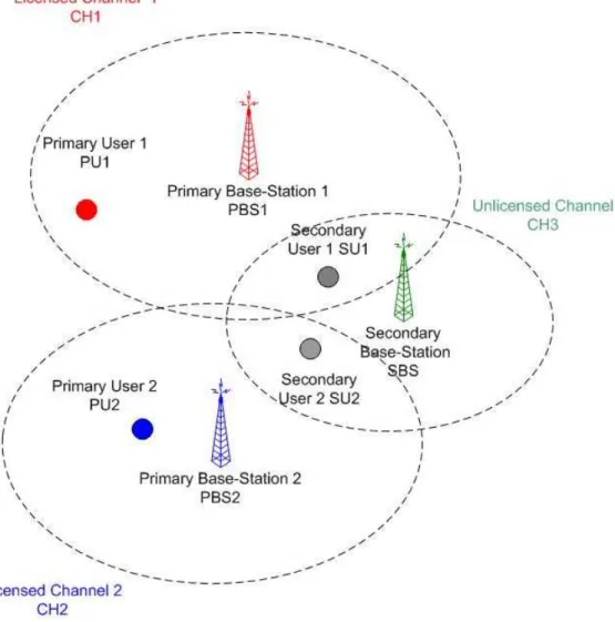
In this thesis, we focus on a CR scenario where the users mainly encounter in the hybrid primary users system and secondary users system as shown in Fig.1.1. In this cognitive radio system, there are primary users 1 and 2 (denoted by PU 1 and PU 2), and two secondary CR users (denoted by SU 1 and SU 2). Let channels 1 and 2 in the licensed band be assigned to PU 1 and PU 2, respectively, while SU 1 and SU 2 are covered by both the primary base station (PBS) and the secondary base station (SBS). Assume that the unlicensed band is already too crowded. Then, the CR nodes SU 1 and SU 2 will check whether channel 1 and 2 are idle. If so, CH 1 and CH 2 can be lent to SU 1 and SU 2. To achieve this purpose, a DSA MAC protocol is needed.
The objectives of this thesis are two folds. First, we focus on comparing the per packet dynamic access latency for CR MAC with dedicated and embedded control channels. Because the secondary users can only use the licensed spectrum from primary users for a short period of time, and must return the borrowed spectrum when any primary user appears. Hence, the dynamic access latency is an important factor for the DSA protocol in CR networks. Therefore, we derive an analytical model to evaluate the dynamic access latency for DSA protocol with dedicated and embedded control channels in CR networks. Based on this model, the optimal control channel bandwidth over total channel bandwidth ratio can be obtained. Furthermore, in order to minimize the per packet dynamic access latency, one can decide to adopt the dedicated or embedded control channel according to the system parameters.
From the per packet access latency, one can know how to satisfy the per user requirements. However, minimizing the per packet access delay may not maximize the system throughput [2]. Secondly, according to the analytical result of the per packet dynamic access latency, we develop an analytical model to calculate the total packets access delay. Furthermore, in order to minimize the total packets dynamic
Figure 1.1: Cognitive Radio System Architecture
access latency, one can decide to adopt dedicated or embedded control channel based on the system parameters.
1.1
Problem and Solution
1.1.1
Per Packet Latency Analysis for Cognitive Radio MAC
with Dedicated and Embedded Control Channels
In this part, the objective is focused on analyzing the impact of various control channel design on the per packet latency performance of the CR MAC with dynamic spectrum access. Access delay to the borrowed licensed spectrum for the secondary CR users should be minimized since the primary user may appear to take back its spectrum any time. Thus, the way of design control channels will affect the access delay of the dynamic channel access. Basically, the design of control channels can be categorized into two kinds: 1) dedicated control channels, in which control and data frames are transmitted at different spectrums; 2) embedded control channels, where the control and data frames are transmitted on the same spectrum.
First, we propose an analytical approach to evaluate the per packet latency of DSA in a CR network with dedicated and embedded control channels. The key ingredient of the analytical approach is the virtual slot concept [3]. We find that, in the case of dedicated control channels, an optimal ratio for the control channel bandwidth over the total bandwidth can be found to yield the minimal access delay. From a viewpoint of per packet access delay, the DSA protocols with dedicated control channels and embedded control channels are compared for various data lengths and different number of users.
1.1.2
Total Packets Latency Analysis for Cognitive Radio
MAC with Dedicated and Embedded Control
Chan-nels
In this part, the objective is focused on analyzing the impact of various control channel design on the total packets latency performance of the CR network with dynamic spectrum access. In the previous part, we focus on the analysis of the per packet access latency. However, minimizing the per packet access delay may not maximize the system throughput [2]. Thus, it is worth considering the total packets access latency issue. Basically, the design of control channels can be categorized into two kinds: 1) dedicated control channels, in which control and data frames are transmitted at different spectrums; 2) embedded control channels, where the control and data frames are transmitted on the same spectrum.
In this part, we develop the analytical model to calculate the total packets access latency according to the principle of the per packet latency model. From a viewpoint of total packets access delay, the DSA protocols with dedicated control channels and embedded control channels are compared for various data lengths and different number of users. From this design guidelines, one can know which kind of control channel design method should be chosen according to the requirements.
1.2
Thesis Outline
The rest of this thesis are organized as follows. Chapter 2 introduces the backgrounds on the multi-channel medium access control protocols. In Chapter 3, we formulate the problem and introduce the system model. In Chapter 4, we describe the analytical model for the per packet and total packets access latency in cognitive radio medium access control with dedicated and embedded control channels. In Chapter 5, we show
some numerical results and get some insights. At last, Chapter 6 gives the concluding remarks and suggestions for future works.
7
CHAPTER 2
Background
In this chapter, first of all, we give an overview on the process of the existing multi-channel MAC protocols [4–19] with dedicated, embedded control multi-channels. Then, we explain why some of them are not suitable for the next generation CR networks. Furthermore, we give the problems for CR MAC with dedicated and embedded control channels, respectively. At last, we formulate the problem and introduce the system model.
2.1
An Overview on Multi-Channel MAC
Proto-cols
In this section, we summarize some current multi-channel MAC protocols. Then, we discuss their operation process and drawbacks.
2.1.1
Dedicated Control Channels Method
The typical operation process for the multi-channel MAC protocols with dedicated control channels [4, 8, 13–16] is shown as Fig.2.1. All nodes have assigned a common (or some) dedicated control channel(s) beforehand. Thus, all nodes can exchange the spectrum usage situation and control packets (request-to-send (RTS) and clear-to-send (CTS)) on common spectrums. Then, after exchanging some control messages,
RTS1 CTS1 RTS2 CTS2 DATA1 DATA2 Control Channel Data Channel 1 Data Channel 2
Figure 2.1: Dedicated control channel approach
Frequency 1 Frequency 2 Frequency 3 RTS1 CTS1 DATA1 RTS2 CTS2 DATA2 Control Phase Data Phase
Figure 2.2: Split phase approach
transmitter and receiver can know which channel is the desired data channel and can communicate on it.
Assigning a dedicated common control channel can give each node a common communication platform and decrease the complexity of spectrum access. However, this operation process may cause the control channel saturation problem (we will discuss in next section) and increase the access latency. Furthermore, this operation process is suitable for CR environment. Thus, this operation can be considered when design a CR MAC protocol.
2.1.2
Common Operation Period Method
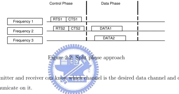
Another kind of MAC protocols with embedded control channels is shown in [6,7,9,17]. The basic idea of this method is to divide total time period into two operation phases:
Frequency 1 Frequency 2 Frequency 3 RTS1 CTS1 DATA1 RTS2 CTS2 DATA2 Time Period 1 Time Period 2 Time Period 3
Figure 2.3: Common hopping approach
control phase and data phase as shown in Fig. 2.2. In the control phase, all nodes can exchange control messages on all channels. In data phase, all nodes can transmit and receive the data frames on the desired data channels.
The authors in [19] propose a multi-channel MAC with hybrid control channels. In this protocol, the control frames (e.q., RTS,CTS) can be transmitted both on control channel and data channels. Furthermore, the control frames can be exchanged not only on control phase, but also on data phase. Thus, this method can increase the channel utilization.
The advantage for this method is no control channel saturation problem. How-ever, this method need all nodes to be synchronized. Furthermore, this method needs to have the operation schedule beforehand. However, this is hard to achieve in CR networks because the spectrum availability is changing from time to time. Thus, nodes are hard to have a transmission schedule beforehand.
2.1.3
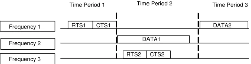
Common Hopping Sequence Method
Another kind of multi-channel MAC protocol is shown in [10, 11, 18]. The basic idea for this method is to use a common hopping sequences to do channel switch as shown in Fig.2.3. Each node uses a hopping sequence to do channel hopping and can communicate with another node once switch to the same frequency band.
Figure 2.4: A scenario uses embedded control channel
This operation process can ignore the control channel saturation problem. However, this method needs all nodes to be tightly synchronized. Furthermore, it needs to have a schedule beforehand and is not suitable for the time-varying CR networks.
2.1.4
Embedded Control Channels Method
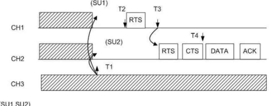
We introduce a CR MAC with the embedded control channels in Fig.2.4. There are two candidate data channels CH 1, CH 2 in this system and CH 2 has the largest idle period.
1. At T1 - In the beginning of the procedure, SU 2 doesn’t have data to transmit and its default channel CH 3 is busy. Thus, SU 2 switches to the idle channel CH 1 even though the CH 2 has the longest idle period.
2. At T2 - The channel with the longest idle period CH 2 becomes idle. Thus, SU 2 switches to CH 2 according to the rule of choosing the channel with the longest idle period.
3. At T3 - SU 1 has data to transmit to SU 2 at this moment. Firstly, SU 1 switches to SU 2’s default channel CH 3 and finds that CH 3 is busy. Thus, SU 1 switches to the channel with the longest idle period CH 2. Then, SU 1 transmits RTS to SU 2 on CH 2 and SU 2 replies CTS to SU 1. Finally, SU 1 can transmit data to SU 2 successfully.
The advantage for this method is without control channel saturation problem. However, this method may have some problems (e.q, channel mismatch problem that we will be discussed in the next section) and increase the access delay. Further-more, this method can be used in CR networks because of no transmission schedule beforehand.
2.2
Summary
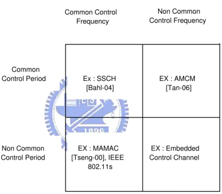
Basically, the design of control channels in multi-channel networks can be categorized into four kinds as shown in Figure 2.5: (I) common control frequency, non common control period (ex: dedicated control channel [4,20–22]); (II) non common control fre-quency, common control period (ex: dedicated control period [6,23,24]); (III) common control frequency, common control period. (ex: common hopping sequence [10, 12]); (IV) non common control frequency, non common control period. (ex: embedded control channel). Because we focus on CR networks, Types II, III are not discussed in this thesis. Thus, we only focus on Type I (called the dedicated control channel) and Type IV (called the embedded control channel) in this thesis.
Common Control Frequency Non Common Control Frequency Common Control Period Non Common Control Period Ex : SSCH [Bahl-04] EX : AMCM [Tan-06] EX : MAMAC [Tseng-00], IEEE 802.11s EX : Embedded Control Channel
13
CHAPTER 3
Problem Formulation
In this thesis, we focus on analyzing the CR MAC with dedicated and embedded control channels. For dedicated control channel case, it has control channel saturation and data channel saturation problems. For embedded control channel, it has channel mismatch problem.
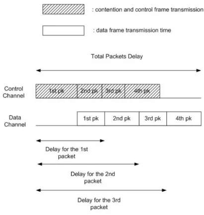
In [2], the authors finds that minimizing the per packet delay may not minimize the total packets delay. From Fig.3.1 and assume there are four packets in the network, one can see that the total packets delay is smaller than four times of the per packet delay. Thus, in this paper, we consider not only the per packet delay but also the total packets delay. The goal of this thesis is to evaluate the per packet and total packets delay by modelling the control and data channel saturation problems in dedicated case and channel mismatch problem in embedded case.
3.1
Saturation Problem with Dedicated Control
Channel
In [25], the authors showed that splitting the total channel bandwidth leads to the control channel saturation issue, thereby degrading the throughput due to the overlong contention duration. Let Tdata be the data transmission duration, Tc the
Pn
i=1Tdata
Pn−1
i=1 Tc < 1, the control channel saturation issue occurs, as shown in Fig.4.1.
One way to mitigate the control channel saturation is to increase the con-trol channel bandwidth. If the concon-trol channel bandwidth increases too much, i.e.,
Pn i=1Tdata
Pn−1
i=1 Tc > 1, the data channel saturation issue occurs as shown in Fig.4.2. In
prac-tice, it is hard to adjust the optimal control channel bandwidth for with varying data lengths and contention durations.
3.2
Problems with Embedded Control Channel
3.2.1
Mismatched Problem
In Fig.3.2, we illustrate the channel mismatched problem using the embedded control channel.
1. At T1 - SU 2 doesn’t have data to transmit and its default channel CH 3 is busy. Thus, SU 2 switches to the idle channel. However, CH 1 and CH 2 are still busy until T1. If SU 1 has data to transmit at T1, SU 1 switches to CH 1 because it has the longest idle period. However, if SU 2 switches to CH 2, then SU 1 and SU 2 can’t exchange data on the same spectrum. We call it the channel mismatched problem.
2. At T2 - SU 1 transmits RTS and waits for the CTS.
3. At T3 - After waiting for a period of RTS timeout and doesn’t receive the CTS, transmitter guesses that SU 2 is not in CH 1. Then, SU 1 switches to the second longest idle period CH 2. Receiver SU 2 finds CH 2 is still idle. Thus, SU 2 stays on CH 2. Thus, SU 1 and SU 2 can transmit data on the same spectrum.
4. At T4 - SU 1 receives a CTS from SU 2. Thus, SU 1 knows that SU 2 is on CH 2. Then, SU 1 can transmit data to SU 2 on CH 2.
Figure 3.2: Channel mismatched case
3.2.2
Contention Problem
If more than one transmitter switch to the same candidate channel, and all of them send RTS at the same time, collision occurs. The solution to the contention problems is to make each transmitter choose a random backoff size for the transmission order. Collision are reduced due to random start time.
3.2.3
Go Back Timer Problem
Another problem for the CR system with embedded control channel is the go back timer problem: Specifically, how long should SU 2 stay on CH 2 to be a receiver? The solution to this problem is to leave the candidate channel CH 2 under two conditions: (1) when CH 2 becomes busy; (2) when the default channel CH 3 is idle (this timer can be known by observing the value of NAV).
Furthermore, how long SU 1 should stay on other candidate channels to be a transmitter is another issue. To solve this problem, SU 1 should go back to SU 2’s default channel when CH 3 becomes idle (this timer can be known from NAV). After that, SU 1 should go back to its default channel when SU 1 transmits to SU 2
successfully.
3.3
Definition of Access Delay for CR MAC with
Dedicated and Embedded Control Channels
Our goal is to evaluate and minimize the access delay for CR MAC with dedicated and embedded control channels as follows. As to dedicated control channel case, the delay
E[D] with considering the control channel and data channel saturation problems:
E[D] = PcsE[D|the kth packet with control channel saturation]
+ PdsE[D|the kth packet with data channel saturation] .
(3.1)
where Pcs and Pds are the saturation probabilities of the control and data channels,
respectively.
As to embedded control channel case, the delay E[D0] with considering the
channel mismatch problems:
E[D0] = E[T ]E[N] , (3.2)
3.4
System Model and Assumptions
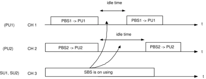
Now, we introduce the system model that we use to evaluate the access delay. Figure 3.3 shows a system model for CR networks, where there are primary users 1 and 2 (denoted by PU 1 and PU 2), and two secondary CR users (denoted by SU 1 and
CH 1 CH 2 CH 3 SBS is on using PBS1 -> PU1 PBS1 -> PU1 t t t PBS2 -> PU2 PBS2 -> PU2 (PU1) (PU2) idle time idle time (SU1, SU2)
Figure 3.3: SU 1 and SU 2 have two candidate idle channels CH 1, CH 2 as shown by two arrows
SU 2). Let channels (CH) 1 and 2 in the licensed band be assigned to PU 1 and PU 2, respectively, while SU 1 and SU 2 are covered by both the primary base station (PBS) and the secondary base station (SBS). Assume that each secondary user has two radio interfaces, where the one is used for receiving and the other one is used for transmitting. It is assumed that all the secondary users can know other’s default channel through the channel discovery procedure and the primary system is TDM based system. Assume that the unlicensed band is already too crowded. Then the CR nodes SU 1 and SU 2 will check whether CH 1 and CH 2 are idle. If so, CH 1 and CH 2 can be lent to SU 1 and SU 2.
19
CHAPTER 4
Latency Analysis
In this chapter, we derive an analytical model to calculate the per packet and total packets dynamic access latency for medium access control protocol with dedicated and embedded control channels in the cognitive radio networks.
The rest of this chapter are organized as follows. Section 3.1 analyzes the per packet dynamic access latency for cognitive radio medium access control protocol with dedicated and embedded control channels. In Section 3.2, we analyze the total packets dynamic access latency for cognitive radio medium access control protocol with dedicated and embedded control channels.
4.1
Per Packet Latency Analysis
In this section, we analyze the average delay of dynamic spectrum access for the CR MAC protocols with dedicated and embedded control channels as described in Chapter 2. The per packet access delay is defined as the duration starting from the instance that an RTS packet is at the head of the queue and starts to content for the transmission until the instance that the associated acknowledgment (ACK) packet for a data packet is received. The total packets access delay is defined as the total deliver time to send total number packets. It is assumed that each CR node always has packets to transmit. In the case of low traffic load, the dedicated case may be better than the embedded. However, in the case of full load, whether the dedicated control
channel is still better than embedded control channel is unknown. Thus, we perform the worst case study to compare the dedicated control channel and the embedded control channels. It is assumed that the channel switching time is zero.
4.1.1
Case I : Dedicated Control Channel
Now we discuss how to calculate the average delay of dynamic spectrum access for the CR MAC protocols with dedicated control channel. Let Pcs and Pds be the
saturation probabilities of the control and data channels, respectively, both of which can be obtained from Fig. 5.1 for a given ratio of control channel bandwidth over data channel bandwidth. With Pcs and Pds, the average access delay of the CR MAC
protocol with dedicated control channel E[D] can be expressed as
E[D] = PcsE[D|the kth packet with control channel saturation]
+ PdsE[D|the kth packet with data channel saturation ] .
(4.1)
Because the probability of the non-saturation event (i.e., E[Tdata]
E[Tc] = 1) is very small,
it is assumed that Pcs+ Pds ' 1 in (4.1).
Delay With Control Channel Saturation
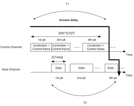
From Fig. 4.1 and the concept of virtual slots proposed in [3], we express the condi-tional average access delay given that the control channel saturation occurs as follows:
E[D|the kth packet with control channel saturation]
= E[T ]E[N(c)] + E[T
data] , (4.2)
where T in this case is the duration of a virtual slot when control channel saturation occurs; N(c) represents the number of virtual slots before the successful transmission
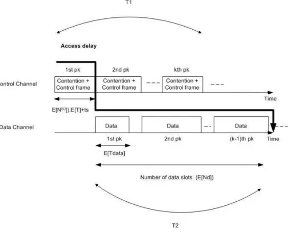
Figure 4.1: The access delay under the control channel saturation (T1=T2)
of an RTS frame; and Tdata is the transmission time of data packets. Note that (4.2)
means a particular node sends out its data packets at kth order and previous k-1 packets may suffer from control or data channel saturation problems.
Before a specifical node transmits an RTS frame successfully, there exists three possible events in each virtual slot. The first one is an empty slot which has probability 1 − Ptr, the second one is that a collided transmission with probability (1 − Ps)Ptr,
and the last one is successful transmission with probability PsPtr. Hence, in terms of
the durations of a successful transmission ts, a collided transmission tf, and an empty
slot σ, it is followed that
E[T ] = (1 − Ptr)σ + (1 − Ps)Ptrtf + PsPtrts , (4.3)
where Ps = nτ (1−τ )
n−1
Ptr is the probability of successful frame transmission; Ptr =
1 − (1 − τ )n is the probability of at least one frame being transmitted, and n is the
number of users. Let p and τ be the probability of collision and that of a station successfully transmitting a packet, respectively. In order to simplify, we consider the infinite retransmission and backoff stages. Then, following the steps in [26], we can get
p = 1 − (1 − τ )n−1 , (4.4)
and
τ = 2(1 − 2p)
(1 − 2p)(W + 1) + pW . (4.5) Then, (4.4) and (4.5) can be solved recursively for given n and W .
According to the IEEE 802.11 MAC protocol,
ts= tRT S+ SIF S + tCT S+ SIF S , (4.6)
and
respectively, where tRT S and tCT S represent the transmission duration of the RTS and
the CTS frames; SIFS and EIFS are the short- and extended-interframe space. Furthermore, given the minimum backoff window size W and the collision probability p, from [3] it can be shown that
E[N(c)] = (1 − p)W + 1 2 + ... +pm(1 − p)(W + 1 2 + ... + 2mW + 1 2 ) + ... = 1 2( W 1 − 2p + 1 1 − p) . (4.8) Substituting (4.3)-(4.8) into (4.2) for a given value of E[Tdata], one can obtain the
average access delay conditional on the occurrence of control channel saturation.
Delay With Data Channel Saturation
Referring to Fig. 4.2, we discuss how to calculate the access delay with data channel saturation. In the figure, there are three possible events in the control channel: idle, successful transmission, and collision. Assume that a node waits for a duration of (E[T ]E[N(c)] + t
s) before successfully transmitting a control frame, where T is the
virtual slot duration; N(c) is the number of virtual slots; and t
s is defined in (4.6).
Specifically, (E[T ]E[N(c)] + t
s) is the duration starting from the beginning of channel
contention until the first data frame transmission. Next, this particular user will need further wait for a duration of (N(d)−1)E[T
data] before transmitting its own data frame,
where N(d) is the average number of transmitted data frames of other users and this
user and E[Tdata] is the average duration of a data frame. Thus, the average access
delay with data channel saturation (denoted by E[D|data channel saturation occurs]) can be expressed as
E[D|the kth packet with data channel saturation]
=¡E[T ]E[N(c)] + t
s
¢
+ E[Tdata]E[N(d)] . (4.9)
Note that (4.9) means a particular node sends out its data packets at kth order and previous k-1 packets may suffer from control or data channel saturation problems.
In the case when no node successfully transmits a control frame, only two events possibly occur at each virtual slot. The first one is an empty slot with the probability of 1−Ptr
1−PsPtr; the second one is a collided transmission with the probability
of (1−Ps)Ptr
1−PsPtr . Hence, the average duration of a virtual slot T in this case can be written
as E[T ] = 1 − Ptr 1 − PsPtr σ + (1 − Ps)Ptr 1 − PsPtr tf . (4.10)
Moreover, given the probability without successful transmissions 1 − PsPtr, the
prob-ability that the number of virtual slots N(c) = k + 1 in the control channel until the
first data frame transmission is equal to (1 − PsPtr)kPsPtr. Hence, it is followed that
the average number of virtual slots N(c)
E[N(c)] = ∞ X k=0 (k + 1)(1 − PsPtr)kPsPtr = 1 PsPtr . (4.11)
To calculate E[N(d)], it is assumed that a particular user successfully sends a
control frame at the first time with k − 1 previous transmitting data frames. The probability Ps(k) that the first data frame of this user as the k − th data frames in
the data channel can be expressed as follows
Ps(k) = µ 1 n ¶ µ 1 − 1 n ¶k−1 . (4.12)
Then, the average total number E[N(d)] of data frames in the data channel including
this user’s frame is equal to
E[N(d)] = ∞ X k=1 k µ 1 n ¶ µ 1 − 1 n ¶k−1 . (4.13) 25
Substituting (4.6), (4.10), (4.11) and (4.13) into (4.9) for a given value of E[Tdata], one
can obtain the conditional average access delay given the occurrence of data channel saturation.
4.1.2
Case II : Embedded Control Channel
Now we consider the access delay D0 for CR MAC with embedded control channel.
When considering a CR MAC with embedded control channels, control channels and data channels use the same frequency spectrum and are not split into two portions in the frequency domain. Applying the virtual slot concept, one can express the average access delay E[D0] as
E[D0] = E[T ]E[N] , (4.14)
where T is the virtual slot duration, and N is the number of virtual slots before the RTS frame is transmitted successfully.
Consider the average virtual slot duration E[T ] first. On the one hand, when establishing a link by dynamic spectrum access, two CR users may choose two different channels in the case of embedded control channel. We call this situation the channel mismatch. In this case, after sending the RTS frame, the transmitter will wait for the CTS until the timeout expires. Let tmismatch be the sum of the time transmitting
the RTS frame and the timeout expiration, i.e.,
tmismatch= tRT S+ DIF S . (4.15)
On the other hand, if the selected channels are matched, the total transmission time of the control frames and data frames (denoted by tmatch) is equal to
tmatch = 2DIF S + tRT S+ tCT S+ 3SIF S
where tACK is the transmission time of the ACK frame; DIFS is the DCF-interframe
space, respectively according to the definitions in the IEEE 802.11 WLAN MAC protocol. Denote Pmatch and Pmismatch as the probability of the channel match and
mismatch, respectively. With m candidate channels, it is followed that
Pmatch = 1 m , (4.17) and Pmismatch = m − 1 m . (4.18)
Recall that the probability with an empty slot is 1 − Ptr, and the probability with
collided transmission is (1 − Ps)Ptr. When considering all the four possible events at
each virtual slot, the average virtual time slot duration E[T ] can be expressed as
E[T ] = (1 − Ptr)σ + (1 − Ps)Ptrtf
+ PmatchPsPtrtmatch
+ PmismatchPsPtrtmisatch , (4.19)
where Tmismatch, Tmatch, Pmatch, and Pmismatch are given by (4.15), (4.16), (4.17), and
(4.18), respectively.
Now, we calculate E[N] in (4.25). Consider m candidate channels. With previous k − 1 mismatched events, the probability of the two CR users select the same channel in the k − th attempt is equal to
m − 1 m · m − 2 m − 1. . . m − k + 1 m − k + 2 · 1 m − k + 1 = 1 m . (4.20)
Before a CR node transmits RTS, it needs to wait for a contention duration. The number of virtual slots before the successful transmission of an RTS frame can be denoted by N(c) as shown in (4.8). With previous k − 1 mismatched events, this node
will undergo kE[N(c)] virtual slots on average. The probability of the occurrence of
the first matched event in k events is 1/m according to (4.20). Thus, E[N] can be expressed as E[N] = m X k=1 1 m · kE[N (c)] = m + 1 2 E[N (c)] . (4.21)
Substituting (4.19) and (4.21) into (4.25) for a given value of E[Tdata], one can obtain
the average access delay for embedded control channel .
4.2
Total Packets Latency Analysis
4.2.1
Case I : Dedicated Control Channel
Now we discuss how to calculate the average whole packets delay of dynamic spectrum access for the CR MAC protocols with dedicated control channel. The similar analyt-ical principle as the per packets delay. With Pcs and Pds, the average whole packets
access delay of the CR MAC protocol with dedicated control channel E[Doverall] can
be expressed as
E[Doverall] = PcsE[Doverall|the last packet with control channel saturation]
+ PdsE[Doverall|the last packet with data channel saturation] .
(4.22)
Total Packets Delay With Control Channel Saturation
Because we now calculate the whole packets delay under the control channel satura-tion. Thus, we calculate the delay until the last packet has been sent. From Fig. 4.3, we express the conditional whole packets access delay given that the control channel
Figure 4.3: The whole packets access delay under the control channel saturation (T1=T2)
saturation occurs as follows:
E[Doverall|the last packet with control channel saturation]
= c(E[T ]E[N(c)] + t
s) + E[Tdata] , (4.23)
where c is the whole number of packets in the network and (E[T ]E[N(c)] + t
s) means
the average delay to send a packet and can be obtained from (4.10), (4.11), (4.6) and (4.7).
Substituting (4.6), (4.7), (4.10) and (4.11) into (4.24) for a given value of
E[Tdata] and c, one can obtain the conditional whole packets delay given the event
that control channel saturation occurs.
Total Packets Delay With Data Channel Saturation
Now, we discuss how to calculate the whole packets delay with data channel satura-tion. We consider the whole packets delay of whole c packets as shown in Fig. 4.4. Firstly, the system wait a duration of the first user’s control frame transmission time equals to (E[T ]E[N(c)]t
s). Because the data channel saturation occurs, we will
cal-culate the latency resulted from c data frames rather than that resulted from control frames. Because there are c data frames need to be transmitted, we can express the conditional whole packets access delay given that the data channel saturation occurs as follows:
E[Doverall|the last packet with data channel saturation]
= cE[Tdata] + (E[T ]E[N(c)]ts) , (4.24)
where c is the whole number of packets in the network and (E[T ]E[N(c)] + t
s) can be
Figure 4.4: The whole packets access delay under the data channel saturation (T2=T1)
Figure 4.5: The whole packets access delay for CR MAC with embedded control channel
Substituting (4.6), (4.7), (4.10) and (4.11) into (4.24) for a given value of
E[Tdata] and c, one can obtain the conditional whole packets delay given the event
that data channel saturation occurs.
4.2.2
Case II : Embedded Control Channel
Now we consider the whole packets access delay D0
overall for CR MAC with embedded
control channel. When considering a CR MAC with embedded control channels, control channels and data channels use the same frequency spectrum and are not split into two portions in the frequency domain. Thus, from the average viewpoint, the whole packets can be seen that distribute uniformly on the whole number of channels (we denote this number as m). Then, we calculate the average time duration to send a complete control frames and a data frame that equal to E[T0]E[N(c)]t0
s. From
embedded control channels E[D0 overall] as E[D0overall] = c m(E[T 0]E[N(c)]t0 s)m = c(E[T0]E[N(c)]t0s) , (4.25)
where T0 is the virtual slot duration, t0
s is the total transmission time of the control
frames and a data frame and E[N(c)] can be obtained from (4.11).
Moreover, base on the similar analysis principle of (4.10), we can express the average duration of a virtual slot T0 on the data channel as follows:
E[T0] = 1 − Ptr 1 − PsPtr σ + (1 − Ps)Ptr 1 − PsPtr t0 f . (4.26) where t0
f is the total duration when collision happens.
According to the IEEE 802.11 MAC protocol, we have
t0
s = 2DIF S + tRT S+ 3SIF S + tCT S+ E[Tdata] + tACK , (4.27)
and
t0f = DIF S + tRT S+ 2SIF S + tCT S . (4.28)
Substituting (4.27), (4.28), (4.26) and (4.11) into (4.25) for a given value of whole packet numbers c, one can obtain the conditional whole packets delay for CR MAC with embedded control channel.
34
CHAPTER 5
Numerical Results
In this section, we first show the relation between the delay of dedicated control chan-nel and the control chanchan-nel bandwidth ratio. Then we compare the per packet and total packets access delay performance of the dedicated control channel and embedded control channel for various user numbers and data sizes. As to the analytical result of the total packets delay, we use 2000 packets to simulate the total packets delay. The related system parameters are listed in Table 5.1. The basic transmission rate is used in each control channel. The data rate is used in each channel for embedded case. In our simulation, it is assumed that data length and the contention period are exponential distribution [27].
5.1
Control Channel Saturation Probability
To calculate the average access delay of the CR MAC with dedicated control channels, we need to obtain Pcs and Pds. Based on the assumptions that the data length
and contention period are exponentially distributed, we simulate the control channel saturation probability in Fig. 5.1. Given average data length and contention duration, some samples are randomly generated. Then we count the samples satisfying the criterion PPni=1Tdata
n−1 i=1 Tc
< 1 to obtain Pcs. Note that Pds ' 1 − Pcs. Figure 5.1 plots the
control channel saturation probability versus the control channel bandwidth ratio. In this figure, one can see that the control channel saturation probability decreases
Table 5.1: System parameters for the control and the data channel RTS 160 bits
CTS 112 bits ACK 112 bits Slot time, σ 20 µsec
SIFS 10 µsec DIFS 50 µsec EIFS 60 µsec
as the the control channel bandwidth ratio increases. The value of control channel saturation probability can be used to calculate the access delay for various control channel bandwidths ratio, which will be shown in the next figure.
5.2
Per Packet Access Latency
5.2.1
Effect of Control Channel Bandwidth Ratio on the
Ac-cess Delay for Dedicated Control Channels
Figure 5.2 shows the effect of control channel bandwidth ratio on the access delay of the CR MAC with dedicated control channels. In the figure, one can see the existence of an optimal control channel bandwidth ratio with the minimum access delay. In the cases with 15 and 20 users, the access delay is minimum when the ratio of the control channel bandwidth over the total bandwidth is about 0.2. Referring to the data channel saturation as show in Fig. 4.2, one can see that a higher control channel bandwidth ratio results in longer access delay because of less bandwidth left for transmitting data frames. Noteworthily, the optimal control bandwidth ratios
Figure 5.1: The effect of control channel bandwidth ratio on the control channel saturation probability
Figure 5.2: The effect of control channel bandwidth ratio on the access delay of the CR MAC for dedicated control channels
are different for various data sizes and contention periods. From this viewpoint, it is difficult to design a predefined optimal bandwidth ratio for a CR MAC with dedicated control channels.
5.2.2
Effect of Number of Users on Access Latency
Figure 5.3 shows the effect of number of users on the CR MAC with dedicated and embedded control channels for the control bandwidth ratio of 0.1 and 0.2. When the ratio is 0.1, the delay for the CR MAC with embedded control channels is always lower than that for the CR MAC with dedicated control channel. For the number of users is 20, the access delay with embedded control channels is 2.5 msec, but the access delay with dedicated control channels is about 4.6 msec. When the optimal ratio 0.2 is considered, the delay for CR MAC with embedded control channel is lower
Figure 5.3: The effect of the different user numbers on the access delay with dedicated and embedded control channels
than that for CR MAC with dedicated control channel only for the case of 17 users. Nevertheless, the optimal control bandwidth ratios for the dedicated control channels varies for different data sizes and contention periods. Thus, it may be hard to trace the optimal bandwidth ratio dynamically.
5.2.3
Effect of Number of Users and Data Lengths on
Con-fidence Interval Comparison of Access Latency
Because the confidence interval can jointly consider the mean and standard deviation, we use confidence interval to compare these two control channel methods.
First, Figure 5.4 shows the confidence interval (90 percent confidence) of the per packet access latency for CR MAC with dedicated and embedded control channels
under small packet length (300 bytes). It shows that when the number of users is not very large (17,18 users), the per packet access delay for the CR MAC with embedded control channels is usually shorter than that the CR MAC with dedicated control channels. This is because that the data transmission rate of embedded case is higher than that of dedicated case. Thus, when the user numbers is small, the embedded case can get smaller delay with higher data rate. But, when the user numbers is large, embedded may suffer from higher contention delay than dedicated case.
Then, Figure 5.5 shows the confidence interval (90 percent confidence) of the per packet access latency for CR MAC with dedicated and embedded control channels under large packet length (2000 bytes). It shows that the per packet access delay of the CR MAC with dedicated control channel is shorter than the CR MAC with embedded control when user numbers is large (over 24 users) and the average data length is large (2000 bytes). The reason is the same as the previous small data length case.
5.2.4
Access Latency Comparison for Three Data Channels
Case
The previous results of per packet delay is considered under two data channels envi-ronments. Because the typical IEEE 802.11 MAC protocol has three data channels, we now discuss the access delay by extending to three primary data channels.
First, Figure 5.6 shows the per packet access latency for CR MAC with dedi-cated and embedded control channels under small packet length (300 bytes). It shows that the per packet access delay for embedded case is usually shorter than dedicated case when the number of users is not very large (15 users).
Then, Figure 5.7 shows the per packet access latency for CR MAC with dedi-cated and embedded control channels under large packet length (2000 bytes). It shows
Figure 5.4: Confidence interval of access latency for CR MAC with dedicated and embedded control channels under small data length
Figure 5.5: Confidence interval of access latency for CR MAC with dedicated and embedded control channels under large data length
Figure 5.6: Access latency for CR MAC with dedicated and embedded control chan-nels under small data length
that the per packet access delay of the CR MAC with dedicated control channel is shorter than the CR MAC with embedded control when user numbers is large (23 users).
5.3
Total Packets Access Latency
5.3.1
Effect of Number of Users on Access Latency
Figure 5.8 shows the effect of different number of users on the total packets delay of the CR MAC with dedicated and embedded control channels. This figure shows that the total packets latency of dedicated case is higher than that of embedded case when the user numbers is not large(under 18 users).
Figure 5.7: Access latency for CR MAC with dedicated and embedded control chan-nels under large data length
Figure 5.8: The effect of number of users on the overall delay of CR MAC with dedicated and embedded cases
5.3.2
Effect of Number of Users and Data Lengths on
Con-fidence Interval Comparison of Access Latency
First, Figure 5.9 shows the confidence interval (90 percent confidence) of the total packets access latency for CR MAC with dedicated and embedded control channels under small data lengths (300 bytes). It shows that the total packets access delay of the CR MAC with dedicated control channel is longer than the CR MAC with embedded control when the average data length is small (300 bytes). Because the embedded case has higher data rate and nodes transmit the small data length, the data transmission time is no longer a bottle neck. Thus, the dedicated will have higher access delay because the dedicated case has lower data rate.
Then, Figure 5.10 shows the confidence interval (90 percent confidence) of the total packets access latency for CR MAC with dedicated and embedded control channels under large data length (2000 bytes). It shows that when the number of users is not large (under 24 users), the total packets access delay for the CR MAC with embedded control channels is shorter than the CR MAC with dedicated control channels. The reason is that when the data length is large, the data channel of dedicated case is usually fully used. Thus, when the user numbers is large, the contention delay will become a bottle neck to embedded case and decrease the system throughput even though the embedded case has higher data rate.
5.3.3
Access Latency Comparison for Three Data Channels
Case
The previous results of total packets delay is considered under two data channels en-vironments. Because the typical IEEE 802.11 MAC protocol has three data channels, we now discuss the access delay by extending to three primary data channels.
Figure 5.9: Confidence interval of access latency for CR MAC with dedicated and embedded control channels under small data length
Figure 5.10: Confidence interval of access latency for CR MAC with dedicated and embedded control channels under large data length
Figure 5.11: Total packets access latency for CR MAC with dedicated and embedded control channels under small data length
First, Figure 5.11 shows the total packets access latency for CR MAC with dedicated and embedded control channels under small packet length (300 bytes). It shows that the total packets access delay of the dedicated case is longer than the embedded case when the average data length is small.
Then, Figure 5.12 shows the total packets access latency for CR MAC with dedicated and embedded control channels under large packet length (2000 bytes). It shows that the total packet access delay of the CR MAC with dedicated control channel is shorter than the CR MAC with embedded control when user numbers is large (over 17 users).
Hence, from the standpoint of access latency, we find that the legacy IEEE 802.11 CSMA/CA MAC protocol is worth extending to CR MAC by adding the
Figure 5.12: Total packets access latency for CR MAC with dedicated and embedded control channels under large data length
channel search capability under some system characteristics. We can conclude that DSA protocol in CR networks can dedicate a certain portion of spectrum for sending control frames if user numbers is large (i.e., 25 users or higher than 1.13 times of the typical 15-user case); otherwise, the embedded control channel shall be considered. Furthermore, from total packets delay viewpoint, when the data length is small (i.e., 300 bytes or lower than 0.29 times of the typical 1024-byte case), the embedded control channel method is suggested to be used even though the user numbers is large.
51
CHAPTER 6
Conclusions and Future Research
Direction
There are two major contributions in this thesis. First, we propose an analytical model to evaluate the per packet dynamic channel access latency for the CR MAC with dedicated and embedded control channels. The per packet access latency for DSA with dedicated and embedded control channels have not been seen in the literature. By using the analytical model, the optimal bandwidth ratio for the dedicated control channel case can be obtained and can know how system parameters affect the latency of the dedicated and embedded control channels. Second, we propose an analytical model to evaluate the total packets dynamic channel access latency for CR MAC with dedicated and embedded control channels. By jointly considering the per packet and total packets cases, a complete design guideline is proposed. In principle, one can know that the legacy IEEE 802.11 CSMA/CA MAC protocol is worth extending for the CR MAC by adding a channel search capability in some suggested conditions.
6.1
Per Packet Latency Analysis
In Chapter 4, from a viewpoint of per packet dynamic channel access latency, we compare the CR MAC with the dedicated control channel and that with the embedded control channels. Then, we analyze the dynamic channel access delay for CR MAC
with dedicated and embedded control channels by applying the virtual slots concept. From our results, we find that, when the number of users is large, the access delay for the CR MAC with embedded control channels is longer than that with dedicated channels. However, the delay performance of DSA with dedicated control channels is more sensitive to the variations of the data lengths compared to DSA with embedded control channels. Based on these observations, one should be able to optimize the control channel design for CR networks.
6.2
Total Packets Latency Analysis
In Chapter 4, from a viewpoint of total packets dynamic channel access latency, we compare the CR MAC with dedicated and embedded control channels. Then, we provide the analysis of total packets dynamic channel access delay for CR MAC with dedicated and embedded control channels by applying the concept of virtual slots.
From our results, we find that, when the average data lengths and user numbers are large, the total packets access delay for the CR MAC with embedded control channels is longer than that with dedicated control channels. This implies that the CR MAC with the dedicated control channels is more suitable for large data length and high user numbers system. Hence, we conclude that the way of dimensioning the spectrum for control frames for DSA in CR networks should be adaptive to the variations of the traffic characteristics and the number of users.
6.3
Suggestions for Future Research
For the future research, we provide the following suggestions to extend our work:
2. take account of the impact of the multi-hop environment on the proposed analyt-ical model;
3. develop an improved DSA protocol with or without dedicated control channel.
54
Bibliography
[1] I. F. Akyildiz, W. Y. Lee, M. C. Vuran, and S. Mohanty, “NeXt Generation/Dynamic Spectrum Access/Cognitive Radio Wireless Networks:A Survey,” Computer Networks, vol. 50, pp. 2127–2159, May 2006.
[2] G. I. P. P. Nico and A. S. Pomportsis, “Distributed Protocols for Ad Hoc Wireless LANs: A Learning-Automata-Based Approach,” Ad Hoc Networks, pp. 419–431, 2004.
[3] P. Chatzimisios, A. C. Boucouvalas, and V. Vitsas, “IEEE 802.11 Packet Delay - A Finite Retry Limit Analysis,” Proceedings of IEEE Global
Telecommunica-tions Conference , pp. 950–954, Dec 2003.
[4] S.-L. Wu, C.-Y. Lin, Y.-C. Tseng, and J.-P. Sheu, “A New Multi-Channel MAC Protocol with On-Demand Channel Assignment for Multi-Hop Ad Hoc Networks,” In Proceedings of International Symposium on Parallel Architectures,
Algorithms and Networks, pp. 232–237, 2000.
[5] A. Nasipuri, J. Zhuang, and S. R. Das, “Multi-Channel CSMA MAC Protocol for Multi-Hop Wireless Networks,” IEEE Wireless Communications and
Net-working Conference, Sept 1999.
[6] J. So and N. Vaidya, “Multi-Channel MAC for Ad Hoc Networks: Handling Multi-Channel Hidden Terminals Using A Single Transceiver,” In Proceedings
of MobiHoc ’04, pp. 222–233, May 2004.
[7] P. Tan and M. C. Chan, “AMCM: Adaptive Multi-Channel MAC Protocol for IEEE 802.11 Wireless Networks,” Third International Conference on Broadband
Communications, Networks, and Systems, Oct 2006.
[8] J. Chen and S. T. Sheu, “Distributed Multichannel MAC Protocol for IEEE 802.11 Ad Hoc Wireless LANs,” Computer Communications, pp. 1000–1013, Dec 2004.
[9] J. H. Chen and Y. D. Chen, “AMNP: Ad Hoc Multichannel Negotiation Protocol for Multihop Mobile Wireless Networks,” IEEE International
[10] P. Bahl, R. Chandra, and J. Dunagan, “SSCH: Slotted Seeded Channel Hopping for Capacity Improvement in IEEE 802.11 Ad Hoc Wireless Networks,” The
ACM Annual International Conference on Mobile Computing and Networking,
pp. 216–230, Sept 2004.
[11] J. N. M and I. T. L., “Spread Spectrum Medium Access Control with Collision Avoidance Protocol for Multichannel Network,” Proceedings of the IEEE
IN-FOCOM , pp. 776–783, 1999.
[12] A. Tzamaloukas and J. J. Garcia-Luna-Aceves, “Channel-Hopping Multiple Access,” IEEE International Conference on Communications, pp. 415–419, 2000. [13] W. C. Hung, K. Law, and A. Leon-Garcia, “A Dynamic Multi-Channel MAC
for Ad Hoc LAN,” 21st Biennial Symposium on Communications, Apr 2002. [14] N. Jain, S. R. Das, and A. Nasipuri, “A Multichannel CSMA MAC Protocol
with Receiver-Based Channel Selection for Multihop Wireless Networks,”
Com-puter Communications and Networks, pp. 15–17, Oct 2001.
[15] C. Y. Chang, H. C. Sun, and C. C. Hsieh, “MCDA: A Efficient Multichannel MAC Protocol for 802.11 Wireless LAN with Directional Antenna,” 19th
In-ternational Conference on Advanced Information Networking and Applications,
pp. 64–67, Mar 2005.
[16] H. Koubaa, “Fairness-Enhanced Multiple Control Channels MAC for Ad Hoc Networks,” IEEE Vehicular Technology Conference, pp. 1504–1508, Jun 2005. [17] J. Chen, S. T. Sheu, and C. A. Yang, “A New Multi-Channel Access Protocol
for IEEE 802.11 Ad Hoc Wireless LANs,” IEEE Personal, Indoor and Mobile
Radio Communications, pp. 7–10, Sept 2003.
[18] Z. Tang and J. J. Garcia-Luna-Aceves, “Hop-Reservation Multiple Access (HRMA) for Ad Hoc Networks,” Proceedings of the IEEE INFOCOM , pp. 194–201, Mar 1999.
[19] S.-C. Lo and C.-W. Tseng, “A Novel Multi-Channel MAC Protocol for Wireless Ad Hoc Networks,” IEEE Vehicular Technology Conference, pp. 46–50, 2007. [20] L. Ma, X. Han, and C. C. Shen, “Dynamic Open Spectrum Sharing MAC
Protocol for Wireless Ad Hoc Networks,” In proceedings of IEEE DySPAN 2005 , pp. 203–213, Nov 2005.
[21] P. Pawelczak, R. V. Prasad, L. Xia, and I. G. M. M. Niemegeers, “Cognitive Radio Emergency Networks - Requirments and Design,” In proceedings of IEEE
DySPAN 2005 , pp. 601–606, Nov 2005.
[22] S. Krishnamurthy, M. Thoppian, S. Venkatesan, and R. Prakash, “Control Channel Based MAC-Layer Configuration, Routing and Situation Awareness for Cognitive Radio Networks,” Proceedings of IEEE Military Communications, pp. 455–460, Oct 2005.
[23] R. Maheshwari, H. Gupta, and S. R. Das, “Multichannel MAC Protocols for Wireless Networks,” Sensor and Ad Hoc Communications and Networks, pp. 393–401, 2006.
[24] Q. Zhao, L. Tong, A. Swami, and Y. Chen, “Decentralized Cognitive MAC for Opportunistic Spectrum Access in Ad Hoc Networks: A POMDP Framework,”
IEEE Journal on Selected Areas in Communications, pp. 589–600, Apr 2007.
[25] J. Deng, Y. S. Han, and Z. J. Haas, “Analyzing Split Channel Medium Access Control Schemes with ALOHA Reservation,” in Ad-Hoc, Mobile, and Wireless
Networks-ADHOC-NOW ’03 , pp. 128–139, 2003.
[26] G. Bianchi, “Performance Analysis of the IEEE 802.11 Distributed Coordination Function,” IEEE Journal on Selected Areas in Communications, pp. 535–547, March 2000.
[27] D. D. Kouvatsos, N. Vlachos, C. Mouchos, and A. Tsokanos, “IP Fragmentation and Framing over Optical Networks : Towards Performance Optimization,”
Vita
Yin-Chih Lu
He was born in Taiwan, R. O. C. in 1983. He received a B.S. in Electronic Engineering from Chung Yuan Christian University in 2005. From July 2005 to July 2007, he worked his Master degree in the Wireless Network Lab in the Department of Communication Engineering at National Chiao-Tung University. His research in-terests are in the field of wireless communications.