Analysis and Application of a Two-Port
Aperture-Coupled Microstrip Antenna
Wen-Jen Tseng and Shyh-Jong Chung,
Member, IEEEAbstract—A two-port aperture-coupled microstrip antenna was analyzed using the method of moments together with a mixed potential integral equation (MPIE). The antenna contains two microstrip-line ports (i.e., a feeding port and a coupling port). The field coming from one microstrip line on the circuit layer is fed into the patch through an aperture on the ground plane. Part of the field is then coupled back to a second microstrip line through another aperture on the same ground. The influences of the stub lengths, along with the positions and sizes of the apertures, on the coupling power and the resonant frequency were investigated. As an application, a feedback antenna oscillator was designed using the present structure where the antenna served not only as a radiator, but also as a feedback resonator. The oscillation was stable and with a clean spectrum at the frequency of 9.79 GHz, which was only 0.2% different from the design one. An effective isotropic radiated power (EIRP) of 39 mW was achieved. The measured cross-polarized fields were at least 15 dB lower than the copolarized ones.
Index Terms— Feedback antenna oscillator, method of mo-ments, tow-port microstrip antenna.
I. INTRODUCTION
A
CTIVE transmitting antennas, which are formed by in-tegrating active circuits with antennas, have attracted much attention due to the advantages of compact sizes, low weights, and low costs. The power in the active antenna is produced from an oscillator in the active circuit and is directly radiated out by the antenna. In most of the de-signs, the antenna was treated as a load of the oscillator [1], [2]; thus, an extra resonator was needed in designing the oscillator. For a more compact configuration as well as a wider injection-locking bandwidth [3], some investigators have used the antenna directly as a feedback resonator of the oscillator [4]–[7]. The antennas used in these designs (which possessed multifunctions) were with two ports, i.e., a feeding and coupling port (to the active circuit). Chang et al. [4], connected the two microstrip-line ports to the nonradiating edges of a patch antenna, while Martinez and Compton [5] and Liao and York [6] attached the feeding microstrip line to the radiating edge and placed the coupling line in the proximity of the nonradiating edge. Since the microstrip lines and the active circuit were fabricated on the same substrate side as the patch was, spurious radiation might be excited and deteriorate the antenna performance in the above designs. Avitabile et al. [7] Manuscript received July 9, 1997; revised December 1, 1997. This work was supported by the National Science Council, Taiwan, R.O.C., under Grant NSC 85-2215-E-009-045.The authors are with the Department of Communication Engineering, National Chiao Tung University, Hsinchu 30039 Taiwan, R.O.C. (e-mail: [email protected]).
Publisher Item Identifier S 0018-9480(98)03166-4.
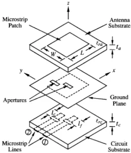
Fig. 1. Geometry of a two-port aperture-coupled microstrip antenna.
used a two-layer configuration where the microstrip lines and the patch were fabricated on different substrates separated by a ground plane. A nonresonant aperture on the ground provided the path for the power coupling between the patch and the two microstrip lines. Although the spurious radiation might be reduced due to the shielding of the ground, the double uses (feeding and coupling) of the aperture would limit the design flexibility and might cause a direct coupling between microstrip lines (due to the close spacing between lines). It is mentioned that none of the above two-port antennas had been analyzed. The antennas were designed experimentally or by using approximate methods.
In this paper, a two-port aperture-coupled microstrip an-tenna, as shown in Fig. 1, is proposed and analyzed. Based on the configuration of the traditional aperture-coupled microstrip antenna [8], [9], an extra slot on the ground plane is fabricated under the patch to couple a fraction of the antenna power to another microstrip line on the circuit substrate. This struc-ture possesses the benefits of the aperstruc-ture-coupled antenna. Furthermore, by changing the position and the size of the second slot, the feedback power can be designed with more flexibility. The method of moments, together with a mixed potential integral equation (MPIE) [10], is used to analyze the antenna structure. To reduce the complexity of the analysis, the microstrip lines are treated with the waveguide model [11], [12]. Finally, as an application, an antenna oscillator using the present configuration is designed and measured.
direction) from the feeding aperture. Both the microstrip lines are symmetrically fed to the apertures with matching stubs of lengths (feeding port) and (coupling port).
The solving procedure in this paper is similar to those in [8] and [9], so only the key steps are mentioned here. First, the -directed electric current (neglecting the -directed current) on the patch antenna is expanded by a set of entire-domain functions. Since the widths of the apertures are electrically small, the electric fields in the two apertures are also assumed to be -directed and are expanded using piecewise sinusoidal functions. Then, by invoking the equivalence principle, the two apertures are closed off and replaced by -directed equivalent magnetic currents above and below the ground plane. To ensure the continuity of the tangential electric fields across the apertures, the magnetic currents below the ground plane should be equal to the negatives of those above (which are denoted by and for the feeding and coupling apertures, respectively). The electric and magnetic fields due to these currents can then be found via the vector and scalar potentials with appropriate Green’s functions [10].
To avoid treating the nonuniform current distributions on the microstrip lines, the lines are modeled as rectangular waveguides [11], [12]. The waveguide consists of a top and bottom electric wall of widths (the effective width of the microstrip line) and two magnetic sidewalls of widths equal to the substrate thickness . The ( -directed) magnetic field associated with the quasi-TEM mode of microstrip-line one (feeding line) can be written as
for for
(1) and the magnetic field of microstrip-line two (coupling line) is given by
for for
(2)
where with being the effective dielectric constant of the waveguide. and are the co-ordinates of the aperture centers. equals the summation of the matching stub’s length and an extension length associated with the open-end effect of the microstrip line. The subscript “ ” and “ ” denote the matching-stub region and the microstrip-line region of or , respectively.
(5)
(6) with being the characteristic impedance of the microstrip
line .
The vanishing of the tangential electric field on the patch and the continuities of the magnetic fields over the two apertures give the following equations:
(7)
(8)
(9) where the fields with a subscript “ ” are related to the currents through the Green’s functions of the ntenna layer, and those with “ ” are through the Green’s functions of the ircuit layer. The superscripts “ ,” “ ,” and “ ” denote that the equations hold over the areas of the atch, the eeding aperture, and the oupling aperture, respectively. By casting (1) and (2) into (7)–(9) and using the relations of (3)–(6), the currents , , and can be solved using the Galerkin’s method of moment, from which the scattering parameters and the radiation fields of the two-port antenna can be obtained.
III. RESULTS FOR TWO-PORT MICROSTRIPANTENNA In this section, numerical results for the two-port aperture-coupled patch antenna are presented. The dielectric constant and the thickness of the antenna substrate are chosen to be and mm, and those of the circuit
substrate are and mm. For an operating
frequency of approximately 10 GHz, the length ( ) and the width ( ) of the antenna patch are, respectively, estimated to be 8.0 and 7.5 mm using the cavity model, and the width of the microstrip lines is calculated as 1.57 mm for a characteristic impedance of 50 . The feeding aperture located under the center of the patch has a fixed size of 4.2 0.58 mm . In the calculation, five entire-domain modes are used to expand the patch current and three piecewise
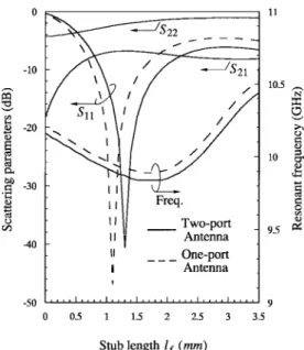
Fig. 2. Calculated scattering parameters and resonant frequency as functions of the feeding stub lengthlf. Substrate parameters:"ra= 2:33, ta= 0:787 mm;"rc= 2:2, tc= 0:508 mm. Patch size: L 2 W = 8.0 2 7.5 mm2. Aperture sizes and distance:Lf2 Wf = Lc2 Wc = 4:2 2 0:58 mm2;
dx= 0; dy= 5:2: mm. Coupling stub length: lc= 2:9 mm. sinusoidal modes are for each of the aperture currents
and .
Fig. 2 illustrates the variations of the scattering parameters and the resonant frequency of the antenna, as functions of the tuning stub length of the feeding port. The coupling aperture has the same size as the feeding one and is placed beside it with a distance of mm ( ). The stub length of the coupling port is specified to be 2.9 mm. For each length , the resonant frequency is found as that with a minimum return loss ( ) in the frequency domain. (The same definition is used for the resonant frequencies in the following figures.) The results for a traditional aperture-coupled antenna with the same dimensions are also calculated and shown for comparison. It is seen that the variations of the return loss and the resonant frequency are approximately the same for the two antennas, which implies that the introduction of the second port has a minor effect on the design of the patch and feed configurations (provided that the coupling between ports ( ) is not too strong). The resonant frequency for the minimum return loss of the two-port antenna is 9.87 GHz (at mm), which is only 0.6% away from that (at mm) of the single-port antenna. Note that while both the return loss and the frequency change dramatically, the coupling power ( ) varies a little with an increase of , as long as the stub length is not in the region of mm where large return losses are obtained ( dB). Also note that due to the weak coupling and the open-end effect, the return loss at port-2 ( ) keeps at large values.
The influence of the coupling stub length on the scattering parameters and resonant frequency are shown in Fig. 3, where the position and the size of the coupling aperture are the same as those in Fig. 2. The feeding stub length is fixed to be 1.2 mm. As can be seen, when changes, the resonant frequency hardly changes and the return loss at the feeding
Fig. 3. Calculated scattering parameters and resonant frequency as functions of the coupling stub lengthlc.lf = 1:2 mm. The other parameters are the same as those in Fig. 2.
Fig. 4. Calculated scattering parameters and resonant frequency as functions of the normalized aperture distance in they-direction (2dy=W ). dx = 0; lf = 1:2 mm, lc = 2:9 mm. The other parameters are the same
as those in Fig. 2.
port remains below 20 dB. This again demonstrates the weak influence of the coupling port on the patch and feed design. On the contrary, with the increase of , the coupling power ( ) increases dramatically from 28 dB (at mm) to 7 dB (at mm), corresponding to a coupling power range as large as 21 dB.
Fig. 4 depicts the variations of the scattering parameters and the resonant frequency as functions of the normalized aperture distance (with ). The aperture sizes are the same as those in Fig. 2 and the stub lengths are fixed to be mm and mm. When the coupling aperture is moved far from the feeding aperture, the two-port antenna acts like a single-aperture antenna, and the return loss and the resonant frequency approach 24 dB and 9.93 GHz,
Fig. 5. Calculated scattering parameters and resonant frequency as functions of the normalized aperture distance in thex-direction (2dx=L). dy= 5:2 mm, lf= 1:2 mm, lc= 2:9 mm. The other parameters are the same as those in
Fig. 2.
respectively (see Fig. 2). At the distance of
( mm), the results correspond to those of Fig. 3 at mm (where the coupling power is a maximum). It is seen that increases by degrees as the distance decreases. A coupling power of 4.2 dB is obtained for
(where the distance between the neighboring aperture edges is only 0.375 mm). On the other hand, the resonant frequency has little change and the return loss of the feeding port remains below 20 dB when the normalized distance is not smaller than 1.39. However, as the coupling aperture gets closer to the feeding one, the resonant frequency starts varying and the return loss becomes larger and larger. At the point of , the return loss raises to 13 dB, which is a result of the strong coupling between the two ports. Note that when the normalized distance is larger than 1.56, the coupling aperture is totally outside the boundary of the patch.
Calculated plots given in Fig. 5 correspond to the scattering parameters and the resonant frequency versus the movement of the coupling aperture in the -direction. The distance between apertures in the -direction ( ) is fixed at 5.2 mm. As is known, the coupling power depends on the level of the magnetic field at the coupling aperture. From the cavity model of the patch antenna, the ( -directed) magnetic field beneath the patch is maximal at and approaches zero near where a virtual magnetic wall is located. Thus, as can be seen in the figure, increasing results in a falling . (Notice that, unlike the present case, the decreasing of in Fig. 4 is caused by the reducing of the coupling aperture’s area under the patch.) Although when the aperture is moved totally outside the patch, the fringing magnetic field still contributes to a nonvanished coupling power. Note that since the coupling is not strong ( dB), the frequency is unchanged and is below 20 dB no matter what the distance is. It should be mentioned that from the symmetry of the cavity field, the results for the movement
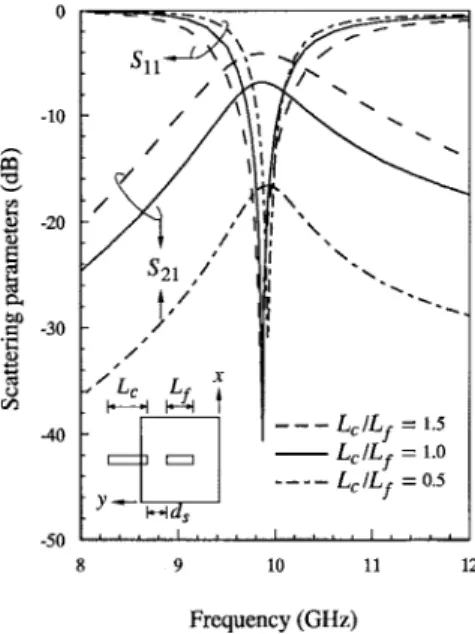
Fig. 6. Calculated frequency responses for the antennas with different cou-pling aperture lengthsLc. The stub lengthslf andlc are, respectively, 1.1 and 4.6 mm forLc=Lf = 0:5, 1:3, and 2:9 mm for Lc=Lf = 1:0, 1:6,
and1:8 mm for Lc=Lf = 1:5. ds = 1 mm. The other parameters are the same as those in Fig. 2.
in the -direction should be the same as those in the -direction, which is exactly the case in our calculation.
Finally, Fig. 6 illustrates the frequency responses for the structures with three different coupling aperture sizes
( , , and ). The distance between the
neighboring edges of the apertures (see the inset) is fixed to be 1.0 mm. For each structure, the stub lengths are adjusted so that a maximum coupling power (minimum return loss) is obtained at the resonant frequency. The resultant feeding ( ) and coupling ( ) stub lengths are, respectively, 1.1 and
4.6 mm for , , and mm for ,
and 1.6 and 2.8 mm for [Note that when the size of the coupling aperture is reduced, the structure is more like a single-aperture antenna, so that the required feeding stub length would approach that (1.1 mm) for a single-aperture antenna (see Fig. 2)]. It is seen that without sacrificing the return loss, increasing the coupling aperture length would raise the coupled power and also increase the bandwidth. The maximum coupling powers for , , and are
16.5, 7, and 4 dB, respectively.
IV. ANAPPLICATION: FEEDBACK ANTENNAOSCILLATOR As an application of the present antenna, we design an -band feedback antenna oscillator with low feedback power (low-resonator factor). The oscillator contains an amplifier and a weak-coupling antenna resonator, as shown in Fig. 7. Extra microstrip lines connecting the two elements are required to adjust the loop phase for oscillation. The power from the output of the amplifier is fed to the feeding port of the antenna, and part of it is then drawn from the antenna coupling port to the input of the amplifier to be enlarged. To start the oscillation, the closed-loop gain should be larger than 0 dB and the electrical length of the loop should be a multiple of at the center frequency. As derived in [13], an oscillator
Fig. 7. Geometry of a feedback antenna oscillator.
Fig. 8. Measured and calculated frequency responses of the two-port an-tenna.lf = 1:538 mm, lc= 1:638 mm. dx= 0, dy= 5:2 mm. The other
parameters are the same as those in Fig. 2.
with low feedback power has the advantage of wide injection-locking bandwidth, which is useful in designing spatial power combining arrays and scanning active antenna arrays [6], [14]. The parameters for the substrates and the patch are chosen as those described in Section III. The commercial software LIBRA is used to design the amplifier with a NE32484A high electron-mobility transistor (HEMT). The measured small-signal gain at the design frequency of 9.81 GHz is 10 dB
[with V and V (or mA)],
which is approximately the same as the simulation one. On the other hand, to satisfy the requirements for oscillation and weak coupling, the antenna coupling power is set as 9 dB, which corresponds to an open-loop gain of 1 dB. To achieve this, we let the two apertures have a same size of 4.2 0.58 mm with a distance mm ( ) and then vary the stub lengths and . The results come out to be mm and mm. With these parameters, a separate two-port aperture-coupled antenna is fabricated and measured. Fig. 8 shows the results. At the center frequency of 9.81 GHz, the return loss of the feeding port is approximately 17 dB and the coupling power is 9 dB. The 10-dB return-loss bandwidth is 3%. It is seen that the numerical results agree quite well with the measurements. Finally, the microstrip-line length for fitting the oscillation phase requirement is evaluated based on the calculated phases of the antenna and the amplifier. By integrating these circuits together, a feedback antenna oscillator design is completed.
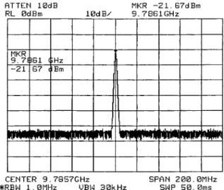
Fig. 9. Measured radiation power spectrum of the feedback antenna oscil-lator.
Fig. 9 shows the measured copolarized radiation power spectrum of the designed antenna oscillator. The oscillating frequency is 9.79 GHz, which is only 0.2% different from the design value. The effective isotropic radiated power (EIRP) is 39 mW, which is calculated using the expression [15]
EIRP (10)
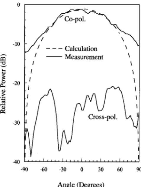
where dB is the antenna gain of the receiving horn antenna, m is the distance between the oscillating antenna and the horn antenna, dBm is the received power, and mm is the free-space wavelength. The front-to-back power ratio is measured to be 8 dB, which is less than the calculated value (13 dB). The extra back-radiating power may come from the radiation of the amplifier and the microstrip-line discontinuities on the circuit substrate. The measured - and -plane radiation patterns are shown in Figs. 10 and 11, respectively. For comparison, the calculated patterns are also presented. Since in the calculation the patch current and the aperture electric fields are all assumed to be -directed, no cross-polarization fields are obtained in the two primary planes. Also, it has to be mentioned that the calculated field patterns of neglecting the radiation from the coupling aperture are approximately the same as those shown in the figures, as is the result of weak coupling design (small induced magnetic current on the coupling aperture). It is seen from Figs. 10 and 11 that the measured 10-dB beamwidth is about 140 in the -plane and 170 in the -plane. The cross-polarization powers are 15 dB ( -plane) and 20 dB ( -plane) lower than the copolarization ones.
V. CONCLUSIONS
In this paper, we have analyzed a two-port aperture-coupled microstrip antenna. The analysis was based on the method of moment coupled with an MPIE, which showed good agreement with the measurement. As an application of the proposed two-port antenna, a feedback antenna oscillator has been designed and demonstrated.
Fig. 10. Measured and calculatedE-plane radiation patterns of the feedback antenna oscillator.f = 9:79 GHz.
Fig. 11. Measured and calculatedH-plane radiation patterns of the feedback antenna oscillator.f = 9:79 GHz.
It was pointed out that provided the coupling between ports is not too strong, the input return loss and the resonant frequency of the antenna are dominated by the configuration of the feeding port. The position and the size of the coupling aperture limit the maximum level of the coupling power. As a rule of thumb, the farther the coupling aperture from the patch center, the lower the coupling power level. In addition, a larger aperture size would result in a higher power level and a wider bandwidth. Also, it was observed that the coupling power could be controlled flexibly by the stub length of the coupling port. Without any tuning, the oscillating frequency of the fabricated antenna oscillator was very close to the design frequency, which demonstrated the accuracy of the design. The active antenna possessed an EIRP of 39 mW with 10-dB beamwidths of 140 in the -plane and 170 in the -plane. The copolarized radiation fields surpassed the cross-polarized ones by at least 15 dB.
Feb. 1994.
[6] P. Liao and R. A. York, “A varactor-tuned patch oscillator for active ar-rays,” IEEE Microwave Guided Wave Lett., vol. 4, pp. 335–337, Oct. 1994. [7] G. F. Avitabile, S. Maci, G. B. Gentili, L. Roselli, and G. F. Manes, “Two-port active coupled microstrip antenna,” Electron. Lett., vol. 28, pp. 2277–2279, Dec. 1992.
[8] P. L. Sullivan and D. H. Schaubert, “Analysis of an aperture coupled microstrip antenna,” IEEE Trans. Antennas Propagat., vol. AP-34, pp. 977–984, Aug. 1986.
[9] D. M. Pozar, “A reciprocity method of analysis for printed slot and slot-coupled microstrip antennas,” IEEE Trans. Antennas Propagat., vol. AP-34, pp. 1439–1446, Dec. 1986.
[10] J. R. Mosig, “Integral equation technique,” in Numerical Techniques for
Microwave and Millimeter-Wave Passive Structures, T. Itoh, Ed. New York: Wiley, 1989, ch. 3.
[11] I. Wolff, “The waveguide model for the analysis of microstrip disconti-nuities,” in Numerical Techniques for Microwave and Millimeter-Wave
Passive Structures, T. Itoh, Ed. New York: Wiley, 1989, ch. 7. [12] A. Ittipiboon, R. Oostlander, Y. M. M. Antar, and M. Cuhaci, “A
modal expansion method of analysis and measurement on aperture-coupled microstrip antenna,” IEEE Trans. Antennas Propagat., vol. 39, pp. 1567–1573, Nov. 1991.
[13] J. Birkeland and T. Itoh, “A 16 element quasi-optical FET oscillator power combining array with external injection locking,” IEEE Trans.
Microwave Theory Tech., vol. 40, pp. 475–481, Mar. 1992.
[14] K. Stephan, “Inter-injection-locked oscillators for power combining and phased arrays,” IEEE Trans. Microwave Theory Tech., vol. MTT-34, pp. 1017–1025, Oct. 1986.
[15] X.-D. Wu and K. Chang, “Novel active FET circular patch antenna arrays for quasi-optical power combining,” IEEE Trans. Microwave
Theory Tech., vol. 42, pp. 766–771, May 1994.
Wen-Jen Tseng was born in Penghu, Taiwan, R.O.C., on October 4, 1972. He received the B.S. degree in communication engineering from National Chiao Tung University, Hsinchu, Taiwan, R.O.C., in 1994, and is currently working toward the Ph.D. degree.
His research interests include electromagnetic theory, microstrip patch antennas, and numerical techniques in electromagnetics.
Shyh-Jong Chung (M’91) was born in Taipei, Taiwan, R.O.C. He received the B.S.E.E. and Ph.D. degrees from National Taiwan University, Taipei, Taiwan, R.O.C., in 1984 and 1988, respectively.
Since 1988, he has been with the Department of Communication Engineering, National Chiao Tung University, Hsinchu, Taiwan, R.O.C., where he is currently a Professor. From 1989 to 1991, he served in the Taiwan Army as a Second Lieutenant, where he was in charge of the maintenance of com-munication equipment. From September 1995 to August 1996, he was a Visiting Scholar in the Department of Electrical Engineering, Texas A&M University, College Station. His areas of interest include propagation and scattering of transmission lines, packaging effects of microwave circuits, numerical techniques in electromagnetics, and the designs and applications of active or passive planar antennas.