472 IEEE MICROWAVE AND WIRELESS COMPONENTS LETTERS, VOL. 15, NO. 7, JULY 2005
Compact and Wideband Microstrip Bandstop Filter
Ming-Yu Hsieh and Shih-Ming Wang
Abstract—A novel one-section bandstop filter (BSF), which pos-sesses the characteristics of compact size, wide bandwidth, and low insertion loss is proposed and fabricated. This bandstop filter was constructed by using single quarter-wavelength resonator with one section of anti-coupled lines with short circuits at one end. The at-tenuation-poles characteristics of this type of bandstop filters are investigated through TEM transmission-line model. Design proce-dures are clearly presented. The 3-dB bandwidth of the first stop-band and insertion loss of the first passstop-band of this BSF is from 2.3 GHz to 9.5 GHz and below 0.3 dB, respectively. There is good agreement between the simulated and experimental results.
Index Terms—Bandstop filter (BSF), microstrip, quarter-wave-length resonator, transmission zero.
I. INTRODUCTION
B
ANDSTOP filter (BSF) is one of the key building blocks in modern communication system. It plays a major role of filtering out the unwanted signals and passing the desired signal. Active devices, such as oscillator and mixer, are often followed by BSFs to remove the higher order harmonics and other un-wanted spurious signals, respectively. Moreover, numerous mi-crowave components including of diplexers and switches are also comprised of BSF.Microstrip-line BSFs have the advantages of cost, low-weight, and ease of implementation. Conventional microstrip BSF [1] is composed of shunt open-circuited resonators that are quarter-wavelength long and straight with connecting lines that are also quarter-wavelength long. These BSFs normally have the narrow stopband. As wide stopband response is required in BSFs, the techniques of photonic band gap (PBG) periodic structures [2] and the defected ground plane (DGS) structures [3] are alternative solutions.
The anti-coupled lines with short circuits at one end reveal characteristics of multiple transmission zeros. Therefore, it is viewed as one kind of frequency-selecting coupling structure (FSCS) in this work. In this work, combining one shunt series open-circuited resonator that is quarter-wavelength long and straight with one section of quarter-wavelength FSCS can induce three transmissions zeros in the stopband. Herein, the quarter-wavelength open-circuited resonator is used instead of the half-wavelength short-circuited resonator since bandpass filter is not the main subject of this work. For the purpose of further miniaturization, other arbitrary open-circuited stubs that are electrically quarter-wavelength long can be adopted as the series resonators. With the aid of extra transmission zeros, the
Manuscript received November 19, 2004; revised January 31, 2005. The re-view of this letter was arranged by Associate Edior M. Mrozowski.
The authors are with National Chiao-Tung University, Hsinchu 300, Taiwan, R.O.C. (e-mail: [email protected]).
Digital Object Identifier 10.1109/LMWC.2005.851572
Fig. 1. Photograph of the proposed BSF.
Fig. 2. Schematic of one FSCS and its equivalent circuit based on TEM-mode.
low-order BSF, which normally has a smaller circuit size and a lower insertion loss, successfully achieve the wide stopband.
II. ANALYSIS OF NOVEL BSF WITHINTEGRATED FREQUENCY-SELECTINGCOUPLINGSTRUCTURE As shown in Fig. 1, the novel BSF structure composed of single open-circuited quarter-wavelength resonator and one sec-tion of quarter-wavelength FSCS was not reported in the past. In Fig. 1, the shunt open-circuited resonator that is quarter-wave-length long at the center frequency of stopband plays the role of series – resonator.
A. Frequency-Selecting Coupling Structure
As shown in Fig. 2, the schematic of lossless FSCS and its equivalent circuit [4] that is based on TEM mode can be ana-1531-1309/$20.00 © 2005 IEEE
HSIEH AND WANG: COMPACT AND WIDEBAND MICROSTRIP BANDSTOP FILTER 473
Fig. 3. (a) FSCS with seriesL–C resonator. (b) FSCS with open-circuited quarter-wavelength resonator.
lyzed by the classical method of even- and odd-mode excitation. The transmission coefficient S [1] is given by
(1) where and are the reflection coefficients, and are the input admittances for even- and odd-mode excitations, and is the system admittance. The transmission-zero condition of FSCS is
(2) where and are the even- and odd-mode characteristic admittances.
From Fig. 2(a) and (2), one transmission zero is induced when at where is the frequency at which the FSCS is quarter-wavelength long. Unfortunately, in microstrip structure, because the even-mode phase velocity of the microstrip cou-pled lines is always slower than that of the odd-mode one, the even-mode electrical length is always larger than odd-mode electrical length for all frequencies. Therefore, this transmis-sion zero is located at the frequency upper . In this work, ad-justing the coupling length slightly longer than quarter-wave-length can move the transmission zero toward and solve this problem.
B. One BSF Unit
In Fig. 3(b), the FSCS and shunt open-circuited resonator have the electrical length of and is the character-istic admittance of resonator. It can be observed that both load-impedance functions (3) and (4) from Fig. 3(a) and (b), respectively, have the same characteristics in the vicinity of
. These equations are listed as
(3) (4)
where .
Fig. 4. Calculated TEM-mode performance of one BSF cell. —DB[S ]; —Im[Y ]; 1 1 1 1 1 1 Im[Y ].
Herein, the BSF structure in Fig. 3(b) is also analyzed by the method of even- and odd-mode excitations. The even- and odd-mode input admittances of one BSF unit are given as
(5a) (5b) where
(5c) The condition of transmission zero is . It indicates that is equal to . The imaginary parts of even- and odd-mode input admittances are given by
(6a) (6b) where
Because and a are larger than and 1, respectively, the created transmission zeros are at the frequencies when
and where is positive. By using (6) to plot Fig. 4, the intersection points show the locations of the transmis-sion zeros. Thus, the wide stopband can be formed as shown in Fig. 4. For this TEM-mode BSF, we adopt 147
70 , and 35 .
In the following, the equations from (4)–(6) for small are given as
(7)
474 IEEE MICROWAVE AND WIRELESS COMPONENTS LETTERS, VOL. 15, NO. 7, JULY 2005
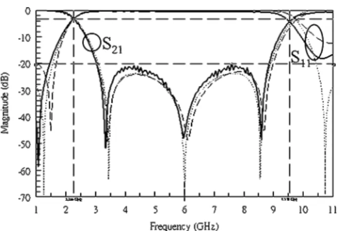
Fig. 5. Calculated TEM-mode simulated EM, and measured performance of one BSF cell. —Measured; —Simulated EM; 1 1 1Calculated TEM-mode.
III. BAND-STOPFILTERSWITHWIDESTOPBAND A planar and wide stopband BSF in Fig. 1 is fabricated by following the procedures listed as follows:
1) decides the center frequency of the fundamental stopband; 2) initially designs the quarter-wavelength resonator and FSCS in the homogeneous medium for satisfying the requirements;
3) chooses appropriate dimensions of quarter-wavelength resonator and FSCS in an inhomogeneous medium; 4) fine adjusts the dimensions of quarter-wavelength
res-onator and FSCS to make agreement between the simu-lated results in homogeneous medium and those in inho-mogeneous medium.
Adjusting the coupling gap of FSCS can control bandwidth of stopband. A smaller gap results in a stronger coupling, thus wider bandwidth is achieved, as indicated in (8). Moreover, a distributed-line resonator of higher characteristic admittance in Fig. 1 also broadens the stopband.
IV. SIMULATED ANDEXPERIMENTALRESULTS To confirm the idea of the novel BSF structure, one-section BSF was fabricated as shown in Fig. 1 on the RO4003 sub-strate with a relative permittivity of 3.38, thickness of 0.508 mm, and loss tangent of 0.0027. This BSF is con-nected to the 50- input and output transmission line. Its cir-cuit size without the SMA connectors and 50- transmission
lines is 3.6 15.5 mm . The parameters of the designed BSF
are 6.8 mm, 2 mm, 8 mm, 0.2 mm, and
0.15 mm. These values are adjusted to fit the performance of TEM-mode BSF.
Fig. 5 shows the simulated and experimental results. It indi-cates that there is good agreement between simulated and mea-sured responses. The simulation is performed with the aid of commercial circuit and Sonnet Software full-wave simulators [5]. The center frequency and 3-dB fractional bandwidth of the proposed BSF is close to 6 GHz and 120%, respectively. An Agilent 8720ES network analyzer is used to perform the mea-surement.
V. CONCLUSION
In this work, we have addressed the design and performance of the proposed BSF with wide stopband. It is noted that the advantage of the proposed BSF over the conventional broad-band BSF is its easiest fabrication and compact size. The im-provement of the stopband of BSF in this work is because of inducing extra transmission zeros in the stopband by means of combining one shunt open-circuited quarter-wavelength res-onator with one section of quarter-wavelength FSCS. Therefore, a novel BSF that balances lower-order resonators, good stop-band performance, simple structure, and uncomplicated design procedure was successfully implemented.
ACKNOWLEDGMENT
The authors would like to thank reviewers, for suggesting sev-eral improvements in this letter’s manuscript, and Dr. Chang, for his valuable suggestions and encouragement.
REFERENCES
[1] J. S. Hong and M. J. Lancaster, Microstrip Filters for RF/Microwave
Applications. New York: Wiley, 2001.
[2] C. Y. Hang, W. R. Deal, T. Qian, and T. Itoh, “High efficiency transmitter front-ends integrated with planar an PBG,” in Asia-Pacific Microwave
Conf. Dig., Dec. 2000, pp. 888–894.
[3] J.-Y. Kim and H.-Y. Lee, “Wideband and compact bandstop filter structure using double-plane superposition,” IEEE Microw. Wireless
Compon. Lett, vol. 13, no. 7, pp. 279–280, Jul. 2003.
[4] G. L. Matthaei, L. Young, and E. M. T. Jones, Microwave Filters,
Impedance-Matching Networks, and Coupling Structures. Norwood, MA: Artech House, 1980.

![Fig. 4. Calculated TEM-mode performance of one BSF cell. — DB[S ]; —Im[Y ]; 1 1 1 1 1 1 Im[Y ].](https://thumb-ap.123doks.com/thumbv2/9libinfo/7524936.119180/2.891.132.364.95.307/fig-calculated-tem-mode-performance-bsf-cell-db.webp)