國
立
交
通
大
學
多媒體工程研究所
碩 士 論 文
使用一對雙環場攝影機成像系統
對視訊監控車周圍的物體做監測之研究
A Study on Monitoring of Nearby Objects around a Video
Surveillance Car with a Pair of Two-camera Omni-directional
Imaging Devices
研 究 生:袁佩瑄
指導教授:蔡文祥 教授
使用一對雙環場攝影機成像系統
對視訊監控車周圍的物體做監測之研究
A Study on Monitoring of Nearby Objects around a Video Surveillance
Car with a Pair of Two-camera Omni-directional Imaging Devices
研 究 生:袁佩瑄 Student:Pei-Hsuan Yuan
指導教授:蔡文祥 Advisor:Wen-Hsiang Tsai
國 立 交 通 大 學
多 媒 體 工 程 研 究 所
碩 士 論 文
A ThesisSubmitted to Institute of Multimedia Engineering College of Computer Science
National Chiao Tung University in partial Fulfillment of the Requirements
for the Degree of Master
in
Computer Science June 2010
使用一對雙環場攝影機成像系統
對視訊監控車周圍的物體做監測之研究
研究生: 袁佩瑄
指導教授:蔡文祥 博士
國立交通大學多媒體工程研究所
摘要
本論文提出了一個以視覺為基礎的視訊監控方法,該方法使用了兩組架設於 監控車車頂的雙環場攝影機成像系統。首先,我們使用空間對應的方法建立起此 環場攝影機成像系統的校正資訊表,稱之為全景對應表。基於此對應表以及兩個 環場影像的對應點,我們提出了影像座標點與世界座標點之間的轉換方法。為了 觀察監控車周遭的環境,我們另提出了建構上視圖的方法,以及將兩張上視圖合 併成一張寬廣視角圖的技巧。此外,我們也使用一區域網路作兩台筆記型電腦的 溝通管道,供傳輸移動指令,讓使用者能移動滑鼠即可建構出各種視角的透視圖。 另一方面,我們提出了一個自動偵測可疑人物並將其標記在上視圖的方法, 這方法使用了一些影像處理的技巧,如距量保存影像二值化和灰階動態補償等。 再者,利用一組雙環場攝影機成像系統所拍攝的影像組,我們能計算出可疑人物 於立體空間中的距離及高度。如果監控車中的使用者想更直接的觀察可疑人物, 他/她也能使用此系統而不需要走出車外即能觀察所建構出的對應透視圖。另 外,我們也提出了一個自動偵測車輛的方法,在該法中,為了移除影像中的地板 區域以及擷取出環場影像中的車體,我們使用了區域生長、組件標籤、圖像變換、 模板匹配等影像處理技巧,並將之有效整合來獲得環場影像中車子的位置。最 後,使用一組雙環場攝影機機成像系統所拍攝的影像組,我們可計算出車子位於 真實世界座標中的位置。 良好的實驗結果顯示我們所提出視訊監控系統的可行性及應用靈活性。A Study on Monitoring of Nearby Objects around
a Video Surveillance Car with a Pair of Two-camera
Omni-directional Imaging Devices
Student: Pei-Hsuan Yuan
Advisor: Prof. Wen-Hsiang Tsai
Institute of Multimedia Engineering, College of Computer Science
National Chiao Tung University
ABSTRACT
Vision-based methods for video surveillance via the use of a pair of two-camera omni-directional imaging devices affixed on the roof of a video surveillance car are proposed. First, a space mapping method is used to construct the so-called pano-mapping tables of the pairs of two-camera omni-directional imaging devices. By the mapping tables and corresponding points of two omni-images, a method for converting the coordinates of the points between the image coordinate system and the world coordinate system is proposed. To see the environment around the video surveillance car, techniques for constructing top-view images and merging them into wider-area integrated ones are proposed. Also, a local network architecture for data communication between two laptop PCs, as well as a technique for constructing perspective-view images of any view direction decided by mouse clicks are proposed. Furthermore, a method for detecting a suspicious passer-by automatically and marking his/her position on a top-view image is proposed, which is based on image processing schemes of moment-preserving thresholding and dynamic grayscale
offsetting. Moreover, the distance and height of a passer-by in 3D space is computed by image pairs taken with a two-camera omni-directional imaging device. If a user in the surveillance car wants to see a detected suspicious passer-by directly, he/she may use the system to generate a corresponding perspective-view image to inspect the suspicious passer-by without going out of the car. Additionally, a method of detecting a passing-by car automatically is proposed. To eliminate the ground region and capture the passing-by car shape in the omni-image, image processing techniques like region growing, component labeling, image transformation, template matching, etc. are used integrally and effectively to get the accurate position of the passing-by car in an omni-image. Finally, the position of the passing-by car in the real world is estimated as well using image pairs taken with a two-camera omni-directional imaging device.
Good experimental results show the flexibility and feasibility of the proposed methods for the application of video surveillance.
ACKNOWLEDGEMENTS
The author is in hearty appreciation of the continuous guidance, discussions, support, and encouragement received from her advisor, Dr. Wen-Hsiang Tsai, not only in the development of this thesis, but also in every aspect of her personal growth.
Thanks are due to Mr. Guo-Feng Yang, Mr. Che-Wei Lee, Mr. Yi-Fu Chen, Mr. Bo-Jhih You, Mr. Jheng-Kuei Huang, Mr. Chih-Hsien Yao, Miss. Mei-Hua Ho, Miss I-Jen Lai for their valuable discussions, suggestions, and encouragement. The author especially thanks Yen-Han Chou for the help in many experiments. Appreciation is also given to the colleagues of the Computer Vision Laboratory in the Institute of Computer Science and Engineering at National Chiao Tung University for their suggestions and help during her thesis study.
Finally, the author also extends her profound thanks to her family for their lasting love, care, and encouragement. The author dedicates this dissertation to her beloved parents and friends.
CONTENTS
ABSTRACT (in Chinese) ... i
ABSTRACT (in English) ... ii
ACKNOWLEDGEMENTS ... iv
CONTENTS ... v
LIST OF FIGURES ...viii
LIST OF TABLES ...xiii
Chapter 1 Introduction ... 1
1.1 Motivation ... 1
1.2 Survey on Related Studies ... 3
1.3 Overview of Proposed Methods ... 6
1.3.1 Terminologies ... 6
1.3.2 Brief Descriptions of Proposed Approach ... 6
1.4 Contributions... 8
1.5 Thesis Organization ... 9
Chapter 2 System Configuration, Camera Design, and Idea of Proposed Method ... 10
2.1 Idea of Proposed Monitoring of Nearby Objects around a Mobile Surveillance Car ... 10
2.2 System Configuration ... 13
2.2.1 Hardware configuration ... 13
2.2.2 Software configuration ... 15
2.2.3 Network configuration ... 16
2.3 Design of a Pair of Two-camera Omni-directional Imaging devices ... 17
2.3.1 System configuration ... 17
2.3.2 Camera Design Principle ... 17
2.3.3 3D data acquisition ... 21
2.4 System Process... 24
Chapter 3 Using Pano-mapping Tables for Unwarping Omni-images into Multi-perspective-view Images ... 27
3.1 Idea of Pano-mapping for Omni- image Unwarping ... 27
3.2 Construction of Pano-mapping Table ... 28
3.2.1 Landmark learning ... 29
3.2.2 Estimation of coefficients of radial stretching function ... 30
3.3 Image Unwarping and Generation of Perspective-view Images ... 34
3.3.1 Generation of a perspective view ... 34
3.3.2 Generation of specified perspective-view images with mouse clicks . ... 38
Chapter 4 Automatic Detection of a Suspicious Passer-by with a Two-camera Omni-directional Imaging Device ... 40
4.1 Introduction ... 40
4.2 Review of Related Concepts in Proposed System ... 40
4.2.1 Moment-preserving thresholding for object segmentation ... 41
4.2.2 Dynamic offsetting ... 43
4.3 Estimation of a Passer-by’s Distance and Height Information ... 44
4.3.1 Detection of moving objects in an omni-image... 44
4.3.2 Detection of a passer-by’s head by component labeling ... 46
4.3.3 Calculation of a passer-by’s distance and height in 3D space ... 50
Chapter 5 Integration of Two Omni-images into a Top-view Image with a Pair of Two-camera Omni-directional Imaging Devices ... 53
5.1 Introduction ... 53
5.2 Construction of a Top-view Image ... 53
5.2.1 Construction of a top-view image with an omni-camera ... 53
5.2.2 Calculation of relative position of two omni-cameras... 57
5.2.3 Merging of two top-view images into a single one ... 58
5.3 Video Surveillance Car Shape Superimposition and Ground Texture Filling in Top-view Image ... 60
5.3.1 Construction of car shape ... 61
5.3.2 Video surveillance car shape superimposition and ground texture filling ... 61
Chapter 6 Automatic Detection of a Passing-by Car with a Two-camera Omni- directional Imaging Device ... 63
6.1 Proposed Idea of Automatic Detection of a Passing-by Car ... 63
6.2 Detection of Car Region in an Omni-image ... 64
6.2.1 Detection of non-ground region ... 64
6.2.2 Detection of car region by region growing and component labeling .. ... 66
6.3 Detection of Car Position in Real World ... 73
6.3.1 Transformation of a car model in real world into an omni-image ... 73
6.3.2 Detection of car position by template matching ... 75
6.4 Passing-by Car Shape Superimposition and Ground Texture Filling in Top-view Image ... 78
6.4.1 Ground Texture Filling ... 78
6.4.2 Passing-by car shape superimposition ... 80
Chapter 7 Experimental Results and Discussions ... 81
7.1 Experimental Results of Pano-mapping Process ... 82
7.2 Experimental Results of Perspective-view Image Generation ... 86
7.3 Experimental Results of Top-view Image Generation and Passer-by Detection ... 87
7.4 Experimental Results of Passing-by Car Detection ... 89
7.5 Experimental Results of Integrated System ... 91
7.6 Discussion ... 93
Chapter 8 Conclusions and Suggestions for Future Works ... 94
8.1 Conclusions ... 94
8.2 Suggestions for Future Works ... 96
LIST OF FIGURES
Figure 1.1 Structures and FOVs of different omni-camera types [Jeng, 3]. (a) Dioptric camera. (b) Catadioptric camera ... 4 Figure 2.1 The video surveillance car used in this study is equipped with a pair of
two-camera omni-directional imaging devices. (a) A front view of the video surveillance car. (c) A side view of the video surveillance car. ... 10 Figure 2.2 Positions of cameras on the video surveillance car roof and the
corresponding images of them. (a) The image captured at the rear-middle of the video surveillance car roof. (b) The image captured at the right-rear of the car roof. ... 11 Figure 2.3 Images of monitoring a passer-by. (a) Top-view image showing surrounding area of the video surveillance car with red mark indicating the passer-by’s position. (b) A corresponding perspective-view image containing the passer-by. ... 12 Figure 2.4 Structure of the proposed monitoring system. ... 14 Figure 2.5 The entire proposed system and the network architecture of transmission.
... 16 Figure 2.6 (a) Two-camera omni-directional imaging device. (b) Two lenses and two
ARTCAM-200SO CMOS cameras. ... 18
Figure 2.7 An illustration of used omni-camera structure. (a) Geometry of the omni-camera vision. (b) Geometry between the mirror and the CMOS sensor in camera. ... 19 Figure 2.8 Computation of depth using the two-camera omni-directional imaging
device. (a) The ray tracing of a scene point P in the imaging device with a hyperbolic-shaped mirror. (b) A triangle in detail (part of (a)). ... 21
Figure 2.9 The system configuration of upper omni-camera with a hyperbolic mirror.
... 23
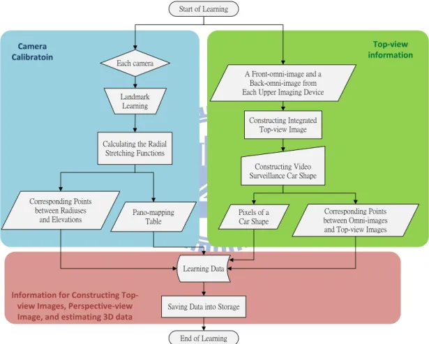
Figure 2.10 Flowchart of proposed learning process. ... 24
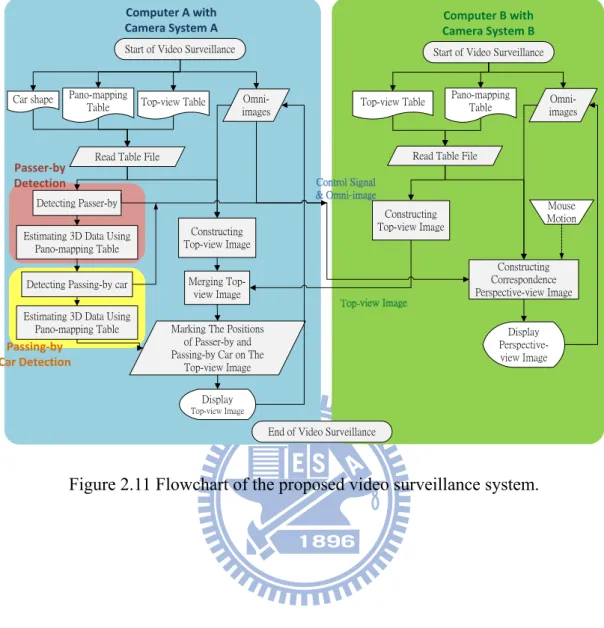
Figure 2.11 Flowchart of the proposed video surveillance system. ... 26
Figure 3.1 The interface for acquiring the data of the world space points ... 29
Figure 3.2 Nonlinear property of an omni-camera with mirror surface shape ... 30
Figure 3.3 Mapping between pano-mapping table and omni-image [8]. ... 32
Figure 3.4 A Top-view configuration for generating a perspective-view image [8]. ... 35
Figure 3.5 A Lateral-view configuration for generating a perspective-view image [8]. ... 37
Figure 3.6 Corresponding omni-image and perspective-view image. (a) A perspective-view image. (b) Omni-image from which (a) was generated. 39 Figure 4.1 A conceptual illustration of a histogram with parameters z0, z1, and t. ... 42
Figure 4.2 Background images of a two-camera omni-directional imaging device. (a) A background taken by an upper omni-camera. (b) A background taken by a lower omni-camera. ... 45
Figure 4.3 Related images of passers-by detection. (a) Background image. (b) Foreground image. (c) The difference image obtained after a subtracting process. (d) The binary image obtained by moment-preserving thresholding [17]. ... 46
Figure 4.4 A specific property of an omni-camera. ... 47
Figure 4.5 The midline of a passer-by through the center of the omni-image. ... 49
Figure 4.6 A result of passer-by’s head detection. (The top of the passer-by’s head is marked in red.) ... 50
Figure 4.7 An overview of passers-by detection proposed in this study. ... 52 Figure 5.1 The ray tracing of a scene point P on the ground with a hyperbolic-shaped
mirror. ... 55
Figure 5.2 An omni-image and its corresponding top-view images. (a) An omni-image. (b) A top-view image obtained from forward mapping. (c) A top-view image obtained from backward mapping. ... 56
Figure 5.3 An omni-image and its corresponding top-view images. (a) An omni-image. (b) A top-view image obtained from forward mapping. (c) A top-view image obtained from backward mapping continued. ... 57
Figure 5.4 An illustration of the layout of the video surveillance car roof. ... 58
Figure 5.5 An integrated top-view image. ... 59
Figure 5.6 An integrated top-view image with a eclipse shape. ... 60
Figure 5.7 An illustration of the video surveillance car shape. ... 61
Figure 5.8 A top view of a car and an integrated top-view image. (a) A top-view image of video surveillance car. (b) An integrated top-view image with video surveillance car shape superimposition and ground texture filling. ... 62
Figure 6.1 A top-view image with a passing-by car. ... 63
Figure 6.2 Flowchart of a passing-by car detection ... 65
Figure 6.3 The interface for ground learning. (a) The omni-image taken by the upper omni-camera. (b) The omni-image taken by the lower one. ... 66
Figure 6.4 The non-ground omni-images. (a) The omni-image taken by the upper omni-camera. (b) The omni-image taken by the lower one. ... 67
Figure 6.5 A flowchart of the region growing we used. ... 68
Figure 6.6 Illustration of calculation of the similarity degree between two image points. ... 70
Figure 6.7 The concept of the component labeling we used. ... 71 Figure 6.8 An example of finding the region of the passing-by car. (a) Result from the
omni-image taken by the lower one. ... 73 Figure 6.9 The cuboids we used. (a) A lateral passing-by car. (b) A parallel passing-by
car. ... 74 Figure 6.10 An example of cuboid shape placement in an omni-image using forward
mapping. ... 74 Figure 6.11 A cuboid shape in an omni-image. (a) Without erosion and dilation. (b)
With erosion and dilation. ... 75 Figure 6.12 An approximate position of the passing-by car. (a) The omni-image taken
by the upper omni-camera. (b) The omni-image taken by the lower one. 76 Figure 6.13 Decision of the passing-by car orientation. ... 77 Figure 6.14 An illustration of template matching. ... 78 Figure 6.15 An illustration of ground filling for the passing-by car shape. (a) The
omni-image. (b) The top-view image. ... 79 Figure 6.16 An illustration of ground filling in a patch-based texture synthesis. ... 79 Figure 6.17 Passing-by car shape superimposition. ... 80 Figure 7.1 An omni-image of a calibration pattern taken by an omni-camera affixed on the ground. ... 82 Figure 7.2 An illustration of picking out pairs of corresponding pixels in two
omni-images. ... 83 Figure 7.3 The regions corresponding to four radial stretching functions. ... 83 Figure 7.4 An experimental result of perspective-view image generation. (a) An
omni-image. (b) The perspective-view image of the left direction. (c) The perspective-view image of the front direction. (d) The perspective-view image of the right direction. ... 86 Figure 7.5 An experimental result of perspective-view image generation. (a) An
perspective-view image of the front direction. (d) The perspective-view image of the right direction continued. ... 87 Figure 7.6 Finding the position of a passer-by’s head in the omni-image. (a) An
omni-image. (b) Result of detection of passer-by’s head. ... 88 Figure 7.7 A real example of detecting a passer-by. (a)~(f) Detection results with red
points marking the feet of the detected person. ... 88 Figure 7.8 A real example of detecting a passer-by. (a)~(f) Detection results with red
points marking the feet of the detected person continued. ... 89 Figure 7.9 A real example of detecting a passing-by car. (a)~(d) Detection results with
a top-view image of a car marking the position of the detected passing-by car. ... 90 Figure 7.10 Real examples of images generated by the integrated system. (a) Example 1.
LIST OF TABLES
Table 2.1 Specifications of the used laptop computers. ... 15
Table 2.2 Specifications of the used COMS cameras ... 18
Table 3.1 Example of pano-mapping table of size M×N [8] ... 32
Table 4.1 r-ρ-Table ... 50
Table 7.1 The results of calculating the values of Wreal by two ways (corresponding to Table 1 with camera 200SO). ... 84
Table 7.2 The results of calculating the values of Wreal by two ways (corresponding to Table 1 with camera 200SO) (continued). ... 85
Table 7.3 The results of calculating the values of Wreal by two ways (corresponding to Table 2 with camera 200SO). ... 85
Table 7.4 The results of calculating the values of Wreal by two ways (corresponding to Table 2 with camera 200SO) (continued). ... 86
Chapter 1
Introduction
1.1 Motivation
As the computer technology progresses quickly nowadays, video cameras are used widely in various surveillance systems, not only to prevent crimes or disasters but also to improve machine automation for human beings’ welfare. The video which is taken by a camera can be recorded forever, and useful information in the video can be extracted for a posteriori investigation. For example, when a car accident occurs or a demonstration is in progression, if a video surveillance car is available aside, the recorded video of the on-going event can be inspected simultaneously or later to find out the cause of the accident or any person who conducted violent activities in the demonstration. Moreover, this way of event recording can provide a better evidence of the possible crime than just relying on the availability of a passenger’s memory of the event’s detail.
In addition, most existing vision-based techniques using traditional cameras only allow recording and processing of frontal scenes, i.e., scenes that are seen in front of the video surveillance car. To improve this shortage, it requires four or more traditional cameras to get a complete coverage of the entire environment around the car. In order to enlarge the fields of view (FOV’s) of traditional cameras, a feasible solution is to use omni-directional cameras (or simply, omni-cameras). In this study, a pair of two-camera omni-directional imaging devices is used. Each device consists of two axis-aligned omni-cameras. A wide and complete view of the environment around a video surveillance car can be covered by such a camera system.
Moreover, most of the vision-based systems are affixed to some places like ceilings or utility poles, each monitoring a specified area around for security screening. In order to increase the mobility of the surveillance area, in this study it is desired to set up a wide-area vision-based surveillance system on the roof of a video surveillance car using the previously-mentioned pair of two-camera omni-directional imaging devices. Once an event like a violent demonstration arises, a police team, for example, may drive the surveillance car to the spot of the event and monitor the event immediately. Such a system may also be utilized to detect suspicious people and vehicles around, and estimate the distance and height information of each approaching passer-by in suspect without walking out the car to measure relevant information manually. This is also a good way to avoid direct contacts between the police team and suspected people.
In addition, about the coverage of the monitored range using a common camera (like a projective one), there usually exist blind areas around a common car which cannot be covered by the camera’s FOV. Therefore, people who are in the car cannot fully watch and understand the environment or the event occurring out there. Furthermore, human eyes can only see a scene with a certain angle span in a single direction at a time, such as a view of the front, the left side, the right side, or the rear of the car. Therefore, a vision-based video surveillance system capable of providing a vehicle user to see the environment outside the car in any direction clearly, dynamically, and conveniently is desirable. It is also advantageous for the user to see easily the top-view image of the surrounding of the video surveillance car and the perspective-view image of any specified direction without turning around his/her body.
As a summary, the research goal in this study is to develop a vision-based video surveillance system on the top of a video surveillance car with a pair of two-camera
omni-directional imaging devices which has the following capabilities:
1. constructing a top-view image of the surrounding of the video surveillance car which comes from merging the two omni-images taken by the upper cameras in the pair of two-camera omni-directional imaging devices (there are two such devices on the top of the surveillance car used in this study, and each device consists of two omni-cameras, an upper one and a lower);
2. constructing a perspective-view image of any direction specified by the car user (the driver or any person in the car), with the view direction determined by mouse clicking or computer panel touching;
3. detecting any suspicious passing-by person automatically, measuring his/her position and height, and marking the result as a moving highlighted spot on the top-view image; and
4. detecting any passing-by car automatically, measuring its position, and marking it on the top-view image.
1.2 Survey on Related Studies
In this study, we use a pair of two-camera omni-directional imaging devices on the top of a video surveillance car to take omni-directional images and estimate relevant 3D data of surrounding objects (passers-by and cars). Omni-cameras can be categorized into two types, dioptric and catadioptric. A dioptric omni-camera captures incoming light with a wide-angle lens. An example of this kind of omni-camera is the
fish-eye camera. Some works of vehicle surrounding monitoring and indoor security
surveillance using fish-eye cameras can be found in Liu, Lin, and Chen [1] and Chen and Tsai [2]. In contrast, a catadioptric omni-camera captures incoming light reflected by a built-in reflective mirror. The mirror surface of a catadioptric omni-camera may
be made to be of various shapes, such as conic, parabolic, hyperbolic, etc. An illustration of the different structures and FOV’s of the two kinds of cameras is shown in Fig. 1.1. CCD Camera CCD Camera ` Incoming light Incoming light Fish-eye Lens Reflective mirror FOV FOV (a) (b)
Figure 1.1 Structures and FOVs of different omni-camera types [Jeng, 3]. (a) Dioptric camera. (b) Catadioptric camera
In this study, we design an imaging device which is composed of two catadioptric cameras in longitudinally coaxial alignment to derive stereo environment information. Most research works used such omni-camera pairs with
hyperbolic-shaped reflective mirrors, such as Koyasu et al. [4] and Ukida et al. [5];
only a few works used such omni-camera pairs with parabolic-shaped reflective mirrors, such as Gluckman et al. [6]. The omni-camera pairs forming an imaging device which we design for use in this study will be elaborated in Chapter 2.
Traditionally, if the intrinsic and extrinsic parameters of the projective camera can be calibrated by a well-known and mature technique, e.g., Salvi et al. [7], stereo information can be obtained using the camera parameters of the omni-camera pairs (see Koyasu et al. [4]). In this study, a space-mapping technique proposed by Jeng and Tsai [8] is used to calibrate the omni-camera without calculating the intrinsic and
extrinsic parameters. In the mean time, there are some image adjustment techniques or calibration methods for adjusting misaligned catadioptric cameras or modifying the image taken by them, e.g., Wu and Tsai [9] and Mashita et al. [10].
Video surveillance has been widely investigated in the past decade. Most research works are about indoor surveillances. Onoe et al. [11] and Mituyosi et al. [12] conducted researches for such a purpose using omni-cameras, both proposing video surveillance systems may be used to monitor passing-by persons and mark their positions on the images. Besides, a video surveillance system using multiple omni-directional cameras was proposed by Morita et al. [13], and it has a capability to detect the positions of moving objects.
In spite of these works, a new capability to obtain pass-by persons’ height as implemented in this study is not found in the previously-mentioned works. Furthermore, the two-camera omni-directional imaging device we use can be used to take images to compute 3D data, and this was not found in the previously-mentioned works, either.
Matuszyk and Zelinsky [14] proposed a method to monitor blind-spots around vehicles using a two-camera omni-directional imaging device with the camera axes aligned horizontally. A wider coverage was obtained because of the designed camera structure. Furthermore, a study that reconstructs 3D data of static near-by vehicles by a mobile robot using a stereo omni-directional camera (a two-mirror omni-directional imaging device) was proposed by Meguro et al. [15]. However, the proposed method for 3D space reconstruction is time-consuming, and this is undesirable in real-time video surveillance. In this study, we propose a new method to detect a passing-by car and mark its position on a top-view image without spending so much time.
1.3 Overview of Proposed Methods
1.3.1 Terminologies
The definitions of some related terms used in this study are described as follows. 1. Omni-directional camera: a camera consists of a reflective mirror and a
traditional camera with a 360-degree field of view in the horizontal plane. 2. Omni-image: an image which is captured with an omni-directional camera. 3. Two-camera omni-directional imaging device: an imaging system
consisting of two omni-cameras coaxially connected in the longitudinal direction, whose detailed configuration will be described in Chapter 2. 4. Perspective view: an image of a scene projected onto a flat surface (such as
paper) as it is seen by the eye from any direction.
5. Top view: an image of a scene projected onto a horizontal plane (with only
x- and y-axis information) as it is seen from the top.
6. Video surveillance car: a car which is equipped with a pair of two-camera omni-directional imaging devices to take video images for the purpose of security surveillance of the environment around the car.
7. Passing-by car: a car which comes to pass by the video surveillance car. 8. Passer-by or passing-by person: a person who comes to pass by the video
surveillance car.
1.3.2 Brief Descriptions of Proposed Approach
There are four major goals in the proposed system as described in the following. 1. A passing-by car should be detected automatically and its position can be
2. A top-view image of the area around the video surveillance car should be made available to an in-car user who wants to monitor such a large area. 3. The monitored area should cover as much of the surrounding environment of
the video surveillance car as possible.
4. A suspicious passer-by’s distance and height with respect to the video surveillance car should be detected and his/her position in 3D space be marked on the top-view image.
5. The perspective-view image in the suspect’s direction with respect to the car should be made available to the user for a clearer inspection.
In order to achieve the previously-mentioned goals, the following major steps are adopted in this study, assuming that a video surveillance car is available:
1. design a two-camera omni-directional imaging device, which consists of an upper omni-camera and a lower one to obtain or estimate relevant 3D data; 2. construct a pair of the imaging devices just mentioned, and equip them on
the roof of the video surveillance car, with one on the front-right corner and the other on the rear-left corner, of the car roof;
3. calibrate each of the four omni-directional cameras in the two imaging devices on the car roof using a space-mapping technique proposed by Jeng and Tsai [8];
4. unwarp the omni-image taken by any of the four omni-cameras into perspective-view images as specified by an in-car user;
5. transfer images by a local network between two processing units (notebook PC’s in this study) used for processing images taken by the pair of two-camera omni-directional imaging devices, respectively;
imaging devices;
7. integrate into a top-view image the two top-view images which are acquired from the two upper omni-cameras of the two imaging devices;
8. detect any suspicious passer-by around the monitored neighborhood of the video surveillance car and show it on a display unit;
9. detect any passing-by vehicle around the monitored car’s neighborhood and show it on a display unit.
Each problem above and the solution proposed for it in this study will be described in detail in the following chapters.
1.4 Contributions
Some contributions made by this study are listed in the following.
1. For the first time multiple omni-directional camera pairs are integrated and used for video surveillance applications.
2. An integrated method using the pano-mapping table based on a space-mapping technique [8] to estimate the 3D data using a two-camera omni-directional imaging device is proposed.
3. A transformation method to convert an omni-image into multiple perspective-view images is derived.
4. A method is proposed to combine two omni-images taken by two separate omni-cameras to obtain an overall top-view image around the video surveillance car.
5. A method of passer-by detection with a two-camera omni-directional imaging device is proposed.
and 3D data extraction is proposed.
7. A local network is constructed, which integrates a pair of two-camera omni-directional imaging devices and two laptop computers for video surveillance use in this study.
8. A method is proposed to solve problems of object detection in images caused by varying light intensities in different weather conditions.
9. A method is proposed to detect the transformed video surveillance car shape from the top-view image, to remove it from the image, and to fill in a graphic car model as a substitute at the correct position, for a better inspection of the image.
1.5 Thesis Organization
In the remainder of this thesis, the system configuration and the idea of the proposed method are introduced in Chapter 2. In Chapter 3, the technique of using the pano-mapping table for unwarping of omni-images into multiple perspective-view images is described. In Chapter 4, the proposed automatic method for detection of a suspicious passer-by with a two-camera omni-directional imaging device is described. In Chapter 5, the proposed method for integration of the two omni-images taken respectively with the two upper omni-cameras into a single top-view image is presented. In Chapter 6, the proposed automatic method for detection of a passing-by car with a two-camera omni-directional imaging device is presented. In Chapter 7, experimental results and discussions are included. Finally, conclusions and some suggestions for future works are given in Chapter 8.
Chapter 2
System Configuration, Camera
Design, and Idea of Proposed
Method
2.1 Idea of Proposed Monitoring of
Nearby Objects around a Mobile
Surveillance Car
In order to monitor the surrounding area of the video surveillance car, we equip on the roof of the car a pair of two-camera omni-directional imaging devices constructed in this study, as shown in Figure 2.1. More details about the devices and the proposed idea of using them are described here.
(a) (b) Figure 2.1 The video surveillance car used in this study is equipped with a pair of
two-camera omni-directional imaging devices. (a) A front view of the video surveillance car. (c) A side view of the video surveillance car.
First, the locations on the car roof where the two imaging devices should be affixed need to be determined. In Figure 2.2, it is illustrated that the video surveillance car body almost accounts for a half of an omni-image taken by an imaging device which is affixed at the middle of the rear edge of the car roof, but it only accounts for a quarter of an omni-image taken by the same imaging device which instead is affixed at the right-rear corner of the car roof. Consequently, an imaging device affixed at a corner of the car roof will have a better view range than one affixed at the front (or back) middle of the car roof. In this study, one of the imaging devices is so affixed at the right-front of a surveillance car roof, and the other is affixed at the left-rear.
(a) (b) Figure 2.2 Positions of cameras on the video surveillance car roof and the
corresponding images of them. (a) The image captured at the rear-middle of the video surveillance car roof. (b) The image captured at the right-rear of the car roof.
The imaging devices, after being affixed, can be used to estimate relevant 3D data of objects (the detail will be described in Chapter 2.3) Then, an integrated top-view image can be obtained to view the surrounding environment of the video surveillance car from the top (the detail will be described in Chapter 5). Also, any passers-by can be detected automatically and be marked on the top-view image (the detail will be described in Chapter 4). If a user wants to see a suspicious passer-by directly, a corresponding perspective-view image may be generated for inspection (the detail will be described in Chapter 3). An example of the top view and a generated perspective view is shown in Figure 2.3.
Furthermore, passing-by cars can also be detected and marked on the top-view image by algorithms proposed in this study, such as region growing, template matching, etc. (the detail will be described in Chapter 6).
(a) (b) Figure 2.3 Images of monitoring a passer-by. (a) Top-view image showing surrounding
area of the video surveillance car with red mark indicating the passer-by’s position. (b) A corresponding perspective-view image containing the passer-by.
2.2 System Configuration
The proposed video surveillance system will be described elaborately in this section. The description will be separated into three parts: hardware configuration, software configuration, and network configuration. The hardware includes the video surveillance car, a pairs of two-camera omni-directional imaging devices, and two laptop computers. The software includes the program used to integrate the vision-based system, the drivers of the omni-cameras, and the program developed by the hhARTRAY Company which is a provider of CCD cameras. However, each two-camera omni-directional imaging device is controlled by a laptop computer, so we construct a local network configuration to handle the problem of communication.
2.2.1 Hardware configuration
The entire hardware structure of the proposed video surveillance system used in this study is shown in Figure 2.4. The video surveillance car we use is named Delica made by Mitsubishi Co. It is a 469cm×169cm×196cm van with a working desk and a power supply designed especially for this study. Its capacity is eight people. For the purpose of connection between four omni-cameras outside the video surveillance car and the two computers inside, four extension cords are used to cross the video surveillance car.
Each of the two-camera omni-directional imaging devices affixed on the video surveillance car roof includes two omni-cameras, and each of the omni-cameras is composed of a lens, a CMOS camera, a mirror, an acrylic tube, and a shelf. The detailed descriptions of these imaging devices, the parameters of the mirrors, and the optical principle of the imaging devices will be described in detail in Chapter 2.3.
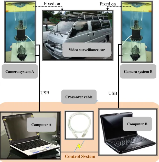
Figure 2.4 Structure of the proposed monitoring system.
As to the control unit, two notebook PC’s are used to integrate the entire video surveillance system. In Figure 2.4, Computer A is a F6E laptop computer produced by ASUSTeK Computer Inc., and Computer B is an A300 laptop computer produced by Toshiba Co. The performance specifications of these computers are shown in Table 2.1. The cross-over cable used for communicating two computers is a Cat-6 cable for the gigabit Ethernet.
Computer A Computer B Cross-over cable Camera system B Camera system A Fixed on Fixed on USB USB
Video surveillance car
Table 2.1 Specifications of the used laptop computers.
ASUS F6E TOSHIBA A300
CPU Intel Core 2 Duo T5850/ 2.16 GHz Intel Core 2 Duo T9400/ 2.53 GHz
Chipset Intel PM 965 Intel GM965
RAM 4 GB DDR2 / 667 MHz 2 GB DDR2 / 800 MHz GPU IntelGMA X3100 ATIRadeon HD 3650 / 512 MB
Network Gigabit LAN Fast Ethernet LAN
2.2.2 Software configuration
We use the Borland C++ builder as the development tool in this study to acquire omni-images and analyze them. It is fast and convenient to develop a GUI-based program using the Borland C++ builder. The programming language we use is C++, a widely-used language. The operating system we use is Window XP.
To access the images taken by the cameras, the computers have to set up the drivers of the ARTCAM-200SO cameras and the ARTCAM-200SS cameras. The Artcam Co. provides a development tool called Capture Module Software Developer
Kit that assists developers in communication with the embedded system of the camera,
using a USB connection. In addition, the SDK is an object-oriented toolkit and usable under Windows 2000 or XP in many languages like C++, C, VB.NET, C#.NET and Delphi. Using the SDK, we can preview the image of each camera’s view and capture the current image data. It is also convenient to use it to develop any function with images grabbed with the cameras as input.
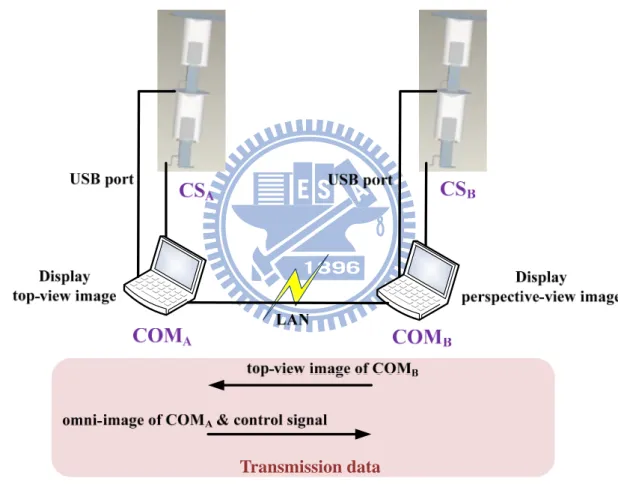
2.2.3 Network configuration
A network configuration is needed for communication between the two laptop computers because four omni-images are acquired from the two pairs of two-camera omni-directional imaging devices (CSA and CSB in Figure 2.5), and each imaging
device is processed by a separated notebook PC (COMA and COMB in Figure 2.5).
The network we propose for this is shown in Figure 2.5.
Figure 2.5 The entire proposed system and the network architecture of transmission.
As shown, COMA is used to display the top-view image of the surrounding area
of the video surveillance car, and COMB to display the perspective-view images in a
specified direction of the car. Therefore, COMB transforms the omni-images gathered
from CSB into a top-view image and transmits the result to COMA which then merges
the two top-view images (one by CSA and other by CSB) into an integrated top-view
image of the car surrounding. On the other side, COMA transmits the omni-image
gathered from CSA and a control signal to COMB, so that COMB knows the view’s
direction and constructs the corresponding perspective-view image.
2.3 Design of a Pair of Two-camera
Omni-directional Imaging devices
2.3.1 System configuration
Each of the two-camera omni-directional imaging devices consists of two omni-cameras combined coaxially in the longitudinal direction, as shown in Figure 2.6(a). The entire system includes four lenses of model LV0612H, two CMOS cameras of model ARTCAM-200SO, and two CMOS cameras of model
ARTCAM-200MI. Two lenses of the four and the two ARTCAM -200SO CMOS
cameras are shown in Figure 2.6(b).
The LV0612H is a mega-pixel lens with the following arguments: 1/2", 6mm, and F1.2. The specifications of the COMS cameras are shown in Table 2.2. Camera
system A in Figure 2.4 is formed with the two ARTCAM-200SO cameras, and affixed
on the right-front of the video surveillance car roof. Camera system B is formed with the two ARTCAM-200MI cameras, and affixed on the left-rear of the video surveillance car roof.
2.3.2 Camera Design Principle
imaging devices (there are four of this kind of camera in our system), we derive the related formulas in the following first.
(a) (b) Figure 2.6 (a) Two-camera omni-directional imaging device. (b) Two lenses and two
ARTCAM-200SO CMOS cameras.
Table 2.2 Specifications of the used COMS cameras
ARTCAM-200SO ARTCAM-200MI
Resolution 2.0 M pixels 2.0 M pixels
Dimension 33mm × 33mm × 50mm 33mm × 33mm × 50mm
CMOS sensor size 1/2” (6.4×4.8mm) 1/2” (6.4×4.8mm)
Mount C-mount C-mount
Frame per second 8 fps 5 fps
Direct show camera Yes No
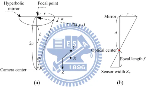
The structure of each omni-camera with a hyperbolic-shaped mirror is illustrated in Figure 2.7, with the world coordinate system (WCS) specified by (X, Y, Z). The hyperbolic shape of the mirror in the camera coordinate system may be described [8] as:
2 2 2 2 2 2 1, , R Z R X Y a −b = − = + (2.1)
where a and b are the parameters of the hyperbolic shape. The parameter d, as shown
in Figure 2.7(b), is the distance between the optical center of the lens and the mirror center, whose value can be obtained by a simple formula d = 2c where c = 2 2
a +b . Also, it is noted that the axis of the camera is aligned with the axis of the hyperbolic mirror, and the camera center is fixed at one of the two focal points of the mirror.
(a) (b)
Figure 2.7 An illustration of used omni-camera structure. (a) Geometry of the omni-camera vision. (b) Geometry between the mirror and the CMOS sensor in camera.
By the geometry of the shape of a hyperboloid described by Eq. (2.1), the value ρ, which specifies an elevation angle shown in Figure 2.7 (a), can be computed by the following formula: 2 2 2 2 ( )sin 2 tan . ( ) cos b c bc b c β α β + − = − (2.2)
1 tan ; 2 r c θ = − (2.3) . 2 π β = − (2.4) θ
In Figure 2.7 (b), by trigonometry, we have ,
w
d f
r = S (2.5)
where, f is a focal length, r is the radius of the circular area of the base of the mirror, and Sw is the width of a CMOS sensor.
Now we can explain how we design the omni-cameras we use in this study according to the above theoretical derivations. The goal is to design a mirror of the hyperbolic shape and determine the distance from the camera to the mirror. Specifically, we have to derive the parameters, a, b, and c, of the hyperbolic shape so that we can ask an optics manufacturer to produce a mirror of such parameters for us. Note that the distance from the camera to the mirror, denoted as d above, is just 2c because we put the camera at such a position that its optical center of the lens is located just at a focal point of the hyperbolic shape, as shown in Figure 2.7.
Because the projective camera we use has a focal length f of 6 mm and a sensor width Sw of 2.4mm, and because the circular area of the base of the mirror has a radius r of 4 cm, according to Eq. (2.5) and d = 2c, we can derive d and c as
10 , 5 . w f d r cm c cm S = × = = (2.5)
Also, according to Eqs. (2.3) and (2.4), the values of the angles θ and β can be computed to be θ = 0.3805 and β = 1.1902. In Eq. (2.2), we can assume α = 0, and by using Eq. (2.4), we can reduce Eq. (2.2) to be the following equation with only one variable b:
2
(b +25) 0.9287 10× − b= (2.6) 0 from which b can be solved to be b = 3.3851. And by c = 5 = a2+b2 , a can be
solved to be 3.6797. Thus, the parameters of the hyperbolic mirror designed in this study are all obtained, that is, a = 3.6797 and b = 3.3851.
2.3.3 3D data acquisition
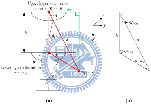
α1 β1 α2 β2 d b P(x,y,z) d b α1-α2 90+α2 90-α1 Upper hyperbolic mirrorcenter 1 (0, 0, 0)
Lower hyperbolic mirror center 2 f1 f2 dw Z X Z Y (a) (b)
Figure 2.8 Computation of depth using the two-camera omni-directional imaging device. (a) The ray tracing of a scene point P in the imaging device with a hyperbolic-shaped mirror. (b) A triangle in detail (part of (a)).
In this section, it will be briefly described how to use two elevation angles of a scene point P to get relevant 3D data. Note that these elevation angles can be obtained by using a pano-mapping table (it will be described in Chapter. 3). Specifically, as shown in Figure 2.8(a), each image point P is a projection of a corresponding point on the hyperboloid, which can be defined by the elevation angles α1 and α2. The upper
is to use α1 and α2 to get (x, y, z).
In Figure 2.8(b), by the triangulation principle, the distance d between the scene point P and the center of a hyperbolic-shaped mirror c1 may be computed as
2 1 2 , sin(90 ) sin( ) d b α = α α + − (2.6) where b is the disparity of the stereo imaging device. In the system we proposed, b = 24.2 cm. Eq. (2.6) can be reduced to the following equation:
1 1 2
1 1
, cos tan tan
d b
α α α
= ×
− (2.7) and the horizontal distance dw and vertical distance Z in Figure 2.8 (a) may thus be computed by: 1 1 2 1 1 1 2 1 cos ; tan tan tan sin . tan tan dw d b Z d b α α α α α α α = = − = = − (2.8)
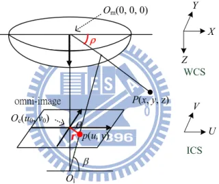
A system configuration of the upper omni-camera with a hyperbolic-shaped mirror is shown in Figure 2.9, with the WCS specified by (X, Y, Z) and the image coordinate system (ICS) specified by (U, V). The I(u, v) is an image point projected by a scene point P(x, y, z).
A triangulation which includes the angle θ in Figure 2.9 can be described by the pixel coordinates (u, v) as follows:
2 2 2 2
sin v ;cos u .
u v u v
θ = θ =
+ + (2.9) As a result of Eq. (2.9), the azimuth θ in the ICS can be computed by the pixel coordinates (u, v) as follows:
1 1 2 2 2 2 sin ( v ) cos ( u ). u v u v θ = − = − + + (2.10)
Figure 2.9 The system configuration of upper omni-camera with a hyperbolic mirror.
According to the characteristic that the axis of the camera is aligned with the axis of the hyperbolic mirror, the azimuth angle θ of point P in the WCS and the azimuth θ angle of point I in the ICS are the same one (according to the rotation-invariant property of the omni-camera). Therefore, the parameters x, y in the GCS can be estimated as follows: 1 2 1 2 cos cos tan tan sin sin tan tan b x dw b y dw θ θ α α θ θ α α = × = × − = × = × − (2.11)
As a result, if an azimuth θ and a pair of elevation angles α1 and α2 are given, the
unique position of a scene point P can be found. The method we use to transform each pixel in an omni-image to an azimuth angle and an elevation angle in the WCS will be described in Chapter 3. Therefore, if a pair of matching points (one is in an omni-image taken by the upper omni-camera, and the other is in an omni-image taken by the lower omni-camera) is known, a relevant 3D data is also obtained.
2.4 System Process
For the purpose of learning all the information that the proposed system can process a video surveillance with the two pairs of two-camera omni-directional imaging devices on the video surveillance car roof, we develop a learning interface for users. The entire learning process is shown in Figure 2.10.
Start of Learning Corresponding Points between Radiuses and Elevations Constructing Integrated Top-view Image Landmark Learning
Calculating the Radial Stretching Functions
Learning Data
A Front-omni-image and a Back-omni-image from Each Upper Imaging Device
Constructing Video Surveillance Car Shape
Pixels of a Car Shape Pano-mapping
Table Each camera
Saving Data into Storage
End of Learning Camera
Calibratoin
Top‐view information
Information for Constructing Top‐ view Images, Perspective‐view Image, and estimating 3D data
Corresponding Points between Omni-images and Top-view Images
Figure 2.10 Flowchart of proposed learning process.
In this study, the recorded data are camera-related and object-related ones. The
camera-related data are used in a transformation to estimate relevant 3D data and a
transformation to construct top-view images. The former is obtained from the camera calibration processes which will be described in Chapter 3, and the latter is obtained from the transformation that transforming an omni-image to a top-view image which
will be described in Chapter 5. The object-related data is a shape of the video surveillance car in top-view image. It is used to construct a top-view image which is not affected by the height of the video surveillance car. The process will be described in detail in Chapter 5.
After all the data are obtained, they are saved into some text files. These files are then used in the video surveillance more than once, so this is also a method for improving the speed of calculations without computing the same data over and over. When the learning job has been done, the video surveillance system can start surrounding monitoring. The entire monitoring process of passers-by in suspect proposed in this study is shown in Figure 2.11.
As shown in Figure 2.11, we read the related table files at the beginning. Computer A is used to show the top-view image, and Computer B is used to show the perspective-view image. The communication of the two computers is described in Section 2.2.3. The construction of a perspective-view image will be described in Chapter 3. The passer-by detection, which yields a red mark in the image, will be described in Chapter 4. The construction of a top-view image and the integration of the two camera Systems will be described in Chapter 5. Finally, The passing-by car detection, which yields a yellow mark in the image, will be described in Chapter 6.
Because both the passer-by detection and passing-by car detection processes require heavy computations, the passing-by car detection process we propose is designed to be independent of the passers-by detection process. Such a compromise approach makes the execution of the two processes smoother.
Start of Video Surveillance
Marking The Positions of Passer-by and Passing-by Car on The
Top-view Image Constructing Correspondence Perspective-view Image Detecting Passer-by Omni-images
Read Table File
End of Video Surveillance
Computer A with
Camera System A Camera System BComputer B with
Start of Video Surveillance
Merging Top-view Image Top-view Table
Read Table File
Constructing Top-view Image
Top-view Table Pano-mapping Table
Constructing Top-view Image Pano-mapping Table Display Top-view Image Display Perspective-view Image Omni-images
Estimating 3D Data Using Pano-mapping Table Car shape
Passer‐by Detection
Detecting Passing-by car
Estimating 3D Data Using Pano-mapping Table
Passing‐by Car Detection
Mouse Motion
Chapter 3
Using Pano-mapping Tables for
Unwarping Omni-images into
Multi-perspective-view Images
3.1 Idea of Pano-mapping for Omni-
image Unwarping
If a suspicious passing-by approaches the video surveillance car, the perspective-view image in the suspect’s direction with respect to the car should be made available to the user in the car for a clearer inspection. This requires unwarping of the omni-images taken with the camera devices used in this study.
Conventional methods for unwarping omni-images require the knowledge of certain camera parameters, like the focal length of the lens, the coefficients of the mirror surface shape equation, etc., to calibrate the camera before omni-image unwarping. However, we cannot get the complete information of the omni-camera parameters in some situations. A solution to this problem is to use the space-mapping technique proposed by Jeng and Tsai [8], as mentioned previously. The technique is based on the use of a pano-mapping table, which may be regarded as a summary of the information conveyed by all the camera parameters. The pano-mapping table is created once forever for each omni-camera and not changed even when the camera is moved around. The table is created by a calibration process making use of certain selected points in the world space with known coordinates and their corresponding pixels in an omni-image. The detail will be described in Section 3.2. The table may be
used to create perspective-view images, as described in Section 3.3.
Another advantage of using the space-mapping technique is that the corresponding relationship of an omni-camera between a radial length r and an elevation angle ρ can also be obtained. The corresponding relationship is defined as a table, called r-ρ Table in this study. Like the method of 3D data extraction described in Section 2.3.3, if two corresponding pixels taken by a two-camera omni-directional imaging device are known, the corresponding elevation angles may derived by use of the r-ρ Table, and the azimuth θ also can be computed by the rotational-invariant property of the omni-camera. Then the unique position of a scene point can be found. This will be very useful in the following chapters for use in detections of passers-by and pass-by cars, for example.
The remainder of this chapter is organized as follows. In Section 3.2, we describe the technique we adopt for pano-mapping table creation in detail. In Section 3.3, we describe the method we use for imaging unwarping and perspective-view image generation based on the use of the pano-mapping table. We also propose a technique to change the view direction with mouse clicks for generation of a corresponding perspective-view image.
3.2 Construction of Pano-mapping
Table
The method proposed by Jeng and Tsai [8] for pano-mapping table construction consists of three major stages: (1) landmark learning, (2) estimation of the coefficients of a radial stretching function describing the geometry of the mirror reflection in the omni-camera, and (3) pano-table creation.
3.2.1 Landmark learning
To construct a pano-mapping table, the first step is to pick out a number of pairs of world space points with known positions and their corresponding pixels in a taken omni-image. More specifically, in this study the coordinates of at least six points, called landmark points hereafter, are measured manually first with respect to a selected origin in the world space. Figure 3.1 shows the interface we have designed for acquiring the data of such landmark point pairs more easily. Especially, note that the origin defined in this study is a focal point of an omni-camera’s hyperbolic mirror. The center Om (in Figure 3.2) of the camera with known world coordinates (X0, Y0, Z0)
just appears to be the image center Oc (in Figure 3.1) with known image coordinates pk(u0, v0). After learning, assume generally that n sets of landmark point pair data are
selected, each set including the image coordinates (uk, vk) with respect to the origin Oc
of the image coordinate system (ICS) and the world coordinates Pk(Xk, Yk, Zk) with
respect to the origin Om of the corresponding world coordinate system (GCS),
respectively, where k = 0, 1, …, n − 1. Also, assume that the pixels of such landmark points in the taken omni-image are already segmented out after being selected on the user interface manually.
Omni-image Landmark point
3.2.2 Estimation of coefficients of radial stretching
function
Owing to the nonlinear property of the hyperbolic mirror surface shape, the radial-directional mapping should be specified by a nonlinear function fr. As shown in
Figure 3.2, we see that each of the elevation angles corresponds to a radial distance, or by notations and more specifically, that each elevation angle ρ of a scene point P corresponds to the radius r of its corresponding image point p.
Om(0, 0, 0) P(x, y, z) p(u, v) omni-image Ol r Oc(u0, v0) U V X Z Y WCS ICS
Figure 3.2 Nonlinear property of an omni-camera with mirror surface shape
Therefore, the radial distance r from each image pixel p with image coordinates (u, v) in the omni-image to the image center Oc at image coordinates (u0, v0) may be
computed by r = fr(ρ). In this study, the function fr, called a radial stretching function,
is approximated by the following 5th-degree polynomial function:
1 2 3 4 5
0 1 2 3 4 5
( ) ,
r
r= f ρ =a + ×a ρ + ×a ρ + ×a ρ + ×a ρ + ×a ρ (3.1) where a0 through a5 are six coefficients to be estimated using the data of the landmark
Step 1. Elevation angle and radial distance calculation ---
Use each landmark point pair (Pk, pk), incluging (Xk, Yk, Zk) in the WCS
and (uk, vk) in the ICS, to calculate the elevation angle ρk of Pk in the WCS
and the radial distance rk of pk in the ICS by the following equations:
1 2 2 tan ( k); , k k k k k Z r u v D ρ = − = + (3.2)
where Dk, is the distance from the landmark point Pk to the mirror center Om
in the X-Y plane of the WCS, computed by 2 2
k k k
D = X +Y .
Step 2. Calculation of coefficients of the radial stretching function ---
Substitute all the data ρ0, ρ1, …, ρn−1 and r0, r1, …, rn−1 computed in Eq.
(3.2) into Eq. (3.1) to get n homogeneous equations as follows:
1 2 3 4 5 0 0 0 1 0 2 0 3 0 4 0 5 0 1 2 3 4 5 1 1 0 1 1 2 1 3 1 4 1 5 1 1 2 3 4 5 1 1 0 1 1 2 1 3 1 4 1 5 1 ( ) , ( ) , ( ) . r r n r n n n n n n r f a a a a a a r f a a a a a a r f a a a a a a ρ ρ ρ ρ ρ ρ ρ ρ ρ ρ ρ ρ ρ ρ ρ ρ ρ ρ − − − − − − − = = + × + × + × + × + × = = + × + × + × + × + × = = + × + × + × + × + × # (3.3)
Finally, solving the above functions to get the desired coefficients (a0, a1, a2, a3, a4, a5) of the radial stretching function fr by a numerical analysis method
[16].
3.2.3 Filling of pano-mapping table entries
The procedure to build a pano-mapping table using the coordinate data of the landmark point pairs is described here. The table is a 2-dimensional one with the horizontal and vertical axes being the azimuth angle θ and the elevation angle ρ, respectively, as illustrated in Figure 3.3.
(a) (b) Figure 3.3 Mapping between pano-mapping table and omni-image [8].
An example of the pano-mapping table of size M×N is shown in Table 3.1. Each entry Eij with indices (i, j) in the pano-mapping table specifies an azimuth-elevation
angle pair (θi, ρj), which represents an infinite set of points in the WCS passing
through by the light ray with azimuth angle θi and elevation angle ρj for the reason
that these world space points in Sij are all projected onto an identical pixel Pij in any
omni-image taken by the camera, forming a pano-mapping fpm from Sij to Pij as shown
in Figure 3.3.
Table 3.1 Example of pano-mapping table of size M×N [8]
This mapping is shown in the Table 3.1 by filling entry Eij with the coordinates
angles into M units, and the range of the elevation angles from ρs to ρe into N units, to
create a table Tpm of M×N entries. Owing to the rotation-invariant property of the
omni-camera, the azimuth angle θ of a space point P with respect to the x-axis in the GCS which the light ray passes is essentially identical to the angle φ of the corresponding pixel p with respect to the u-axis in the input image I. Hence, θ =φ. Each image point p in the ICS with respect to image center Oc may be computed by
Eq. (3.1). Accordingly, the entries of table Tpm may be filled by the following
algorithm [8].
Step 1. Divide the range 2π of the azimuth angles into M intervals, and the ith azimuth angle θi can be described by
(2 / ), for 0, 1, ..., 1.
i i M i M
θ = × π = − (3.4) Step 2. Divide the range (ρe−ρs) of the elevation angles into N intervals, and
describe the jth elevation angle ρj by
[( ) / ] , for 0, 1, ..., 1.
j j e s N s j N
ρ = × ρ −ρ +ρ = − (3.5) Step 3. Regard the pairs ( , ) ( ( ), )r φ = fr ρ θ of all the image pixels to form a polar
coordinate system with the image coordinates (u, v) specified by cos ( ) cos ; sin ( ) sin .
ij j i r i ij j i r i
u = ×r φ = f ρ × θ v = ×r φ = f ρ × θ (3.6) Step 4. Based on Eqs. (3.1) and (3.6), fill the entry Eij with corresponding image
coordinates as follows:
cos ; sin ,
ij j i ij j i
u = ×r θ v = ×r θ (3.7) where rj is computed by
1 2 3 4 5
0 1 2 3 4 5
( ) ,
j r j j j j j j
r = f ρ =a + ×a ρ + ×a ρ + ×a ρ + ×a ρ + ×a ρ (3.8) with the coefficients (a0, a1, a2, a3, a4, a5) computed in the way as described in
Section 3.2.2.
3.3 Image Unwarping and Generation
of Perspective-view Images
3.3.1 Generation of a perspective view
According to above-mentioned information, the procedure to construct a perspective-view image from an omni-image with the aid of a pano mapping table is described in the following.
Input: an omni-image G, a pano-mapping table Tpm (with M × N entries), and a planar
rectangular region (W × H) at a distance D with respect to the mirror center Om.
Output: a perspective-view image Q of any size MQ × NQ.
Idea:
(A) Map each image pixel qkl in Q at coordinates (k, l) to an entry Eij in Tpm filled
with coordinates pixel (uij, vij).
(B) Assign the color value of the pixel pij of G at (uij, vij) to qkl.
A top view of the configuration for such an image generation process is shown in Figure. 3.4, and the above idea will be accomplished by the following two steps [8], computing the azimuth angles θq and elevation angle ρq associated with Eij and
(a) (b) Figure 3.4 A Top-view configuration for generating a perspective-view image [8].
Steps:
Step 1. Computing θq associated with Eij and corresponding to qkl ---
Referring to Figure 3.4, the angle φ can be derived by trigonometry to be as follows: 2 2 2 2 1 2 2 cos ; cos [1 ]. 2 W D D D D W D φ φ − = + − × × × = − × (3.9)
Also, β in the figure may be derived to be:
2
π φ
β = − . (3.10)
Next, we compute the index i of entry Eij of table Tpm corresponding to
pixel qkl in image Q. First, let Pij denote the intersection point of the light ray Rq projected onto qkl and the planar projection region Ap. Note that each entry Eij has a corresponding Pij. Then, we compute the distance d between point Pij
and the border point Pr shown in Figure 3.4 by linear proportionality as
, W
d = ×k (3.11)
where the projection region Ap has a width of W, the image Q has a width of MQ pixels, and pixel qkl has an index of k in the horizontal direction.
In Figure 3.4(b), we also can compute the distance L between point Pij
and the mirror center Om by trigonometry as follows: 2 2 2 cos ,
L= D +d − × × ×d D β (3.12)
and then the distance h from point Pij to the line segment O Pm r connecting Om and pr as:
sin .
h d= × β (3.13) Therefore, the azimuth θq of point Pij with respect to O Pm r satisfies
2 2 sin sin , 2 cos q h d L D d d D β θ β × = = + − × × × (3.14) which leads to 1 1 2 2 sin sin sin [ ]. 2 cos q h d L D d d D β θ β − − × = = + − × × × (3.15) Finally, the index i of entry Eij may computed by linear proportionality
as 2 q i θ M π = × . (3.16)
Step 2. Computing ρq associated with Eij and correspond to qkl ---
An illustration of the involved imaging configuration from a lateral view is shown in Figure 3.5. The height of the projection region Ap is H and the
![Figure 1.1 Structures and FOVs of different omni-camera types [Jeng, 3]. (a) Dioptric camera](https://thumb-ap.123doks.com/thumbv2/9libinfo/8146372.166918/19.892.142.756.281.728/figure-structures-fovs-different-camera-types-dioptric-camera.webp)

![Table 3.1 Example of pano-mapping table of size M×N [8]](https://thumb-ap.123doks.com/thumbv2/9libinfo/8146372.166918/47.892.186.709.101.327/table-example-pano-mapping-table-size-m-n.webp)
