國
立
交
通
大
學
資訊科學與工程研究所
博 士 論 文
人臉偵測之研究
A Study on Face Detection
研 究 生: 井 民 全
指導教授: 陳 玲 慧 教授
人臉偵測之研究
A Study on Face Detection
研 究 生:井民全
Student: Min-Quan Jing
指導教授:陳玲慧
Advisor: Dr. Ling-Hwei Chen
國 立 交 通 大 學
資 訊 科 學 與 工 程 研 究 所
博 士 論 文
A Dissertation
Submitted to Institute of Computer Science and Engineering College of Computer Science
National Chiao Tung University in partial Fulfillment of the Requirements
for the Degree of Doctor of Philosophy
in
Computer Science
June 2009
Hsinchu, Taiwan, Republic of China
中華民國九十八年七月
人臉偵測之研究
研究生:井民全 指導教授:陳玲慧博士
國立交通大學資訊學院 資訊工程系
摘要
近年來
,數位安全監控技術的普遍發展
,使得完全自動化的人臉
系統 (fully automated face system) 越來越受到重視。人臉偵測是自動
化人臉系統的基石,任何人臉應用系統都需要有一個強固的人臉偵測
方法,才能達到預期的效果,因此人臉偵測的研究與分析便顯得重要
而且迫切。雖然人臉偵測方法的研究已經超過 20 年,也有許多成果
已經發表。可是對於多變化環境下的人臉偵測,特別是針對不同人臉
角度 、不同光源方向與有顏色光源的人臉位置偵測方法,依然是一
項十分具挑戰性的研究領域。
一般人臉偵測方法的主要架構大致是由下列幾項要素組成: 人臉
候選位置的判定、臉部特徵的擷取與人臉位置的偵測。可是由於多變
化的環境,導致人臉偵測的困難。例如在研判人臉可能出現的位置
時,就可能受取像時的環境條件所影響,有顏色的光源與不同角度的
側面光源,如不加以考量就會影響人臉候選位置的判定。另外由於攝
影機與人臉之間的取像角度,使得人臉在影像中所呈現的姿勢可能為
正面、接近正面、半側面、側面等,一些重要的臉部特徵如眼睛,卻
可能會因為影子、眼鏡和人臉姿勢的關係導致偵測錯誤。而不同的臉
部表情也會產生不同的臉部呈現樣式。這些因素增加了人臉偵測的困
難性。本論文之主要目的在於提出一個解決上述問題的人臉偵測方
法。
在本論文中,我們首先將會提出一個在多變化環境下的眼睛水平
線偵測方法,利用膚色資訊將人臉可能所在的區域標記出來,然後根
據人類眼睛擁有的非膚色特性與高亮度(gray-level)變化特性,將眼睛
的位置標示出來,最後利用人臉的幾何特性將眼睛水平線標記定位。
這個方法主要的貢獻在於提出一個有效的方法,取得多變化環境下的
眼睛候選位置與水平線資訊。接下來,利用得到眼睛水平線位置與眼
睛可能位置座標,發展一個在多變化環境下不同姿勢的人臉偵測方
法。首先將膚色資訊所標記出來的人臉區域進行肩膀區域的判定與刪
除,接著利用定義好的側面人臉特徵幾何規則將人臉區域分成側面人
臉或非側面人臉區域。對於非側面的人臉候選區域,利用前述方法取
得眼睛水平線與眼睛可能位置座標。最後針對不同人臉姿勢與人臉亮
度分佈的特性,標記出真正的眼睛位置並藉此將人臉位置標示出來。
本論文所提出的方法,經過標準人臉資料庫實驗證實,可以解決人臉
偵測在多變化環境下所遭遇的問題。
A Study on Face Detection
Student: Min-Quan Jing Advisor: Dr. Ling-Hwei Chen
Institute of Computer Science and Engineering National Chiao Tung University
ABSTRACT
While digital surveillance systems are receiving increasing concern in
modern society, developing a fully automated face system is getting more and more
attentions than before. However, a robust face detector is a foundation of building an
automated face system. Face detection method insures a face system realizable. Thus,
the demand for an efficient method to automatically detect face becomes urgent.
Although face detection has been studied for more than 20 years, developing a
human face detector under various environments is still a challenging task. An
automatical face-detection job would include three steps: face candidate location,
facial feature extraction and face detection. Some factors make face location difficult.
One is the variety of colored lighting sources, another is that facial features such as
eyes may be partially or wholly occluded by shadow generated by a bias lighting
direction; others are races and different face poses with/without glasses. These factors
make face detection difficult. The aim of the research is to provide a solution to these
of a face under various environments. Based on the facts that the eye color is very
different from skin color and the gray level variance of an eye is high, some eye-like
regions are located. Then the horizontal eye line is extracted based on the located
eye-like regions and some geometric properties in a face. The contribution of this
method is providing information of eye-like region positions and human horizontal
eye line under various environments. Next, a method based on the extracted eye-like
region position and horizontal eye line information will be proposed to detect a face
with different poses under various environments. The basic idea is, first, skin regions
are extracted from an input image using skin color information and then the shoulder
part is determined and cut out by using shape information. The remained head part is
identified as a face candidate. For a face candidate, we apply a set of geometric
features to determine if it is a profile face. If the face candidate is a non-profile face,
then a set of eye-like rectangles extracted from the face candidate and the lighting
distribution are used to determine. Solving the poses problem and detecting face
location under various environments are the main contributions of this method.
Experimental results show that the proposed method is robust under a wide range of
誌 謝
首先要對我的指導教授陳玲慧博士獻上我最誠摯的感謝。在她細心與熱心的 指導下,讓我能夠完成博士論文。從她身上我學習到豐富的知識與嚴謹的態度, 更重要的是,我從她身上學習到真誠待人的處事原則。她是幫助我最多的人,在 我的人生中,我很幸運能夠遇到這麼一位這麼好的老師。 接著我要特別感謝的人是李建興學長,他在我最需要幫忙的時候伸出援手並 且給我溫暖的建議與打氣。林瑞祥學長,在我困難的時候幫我排除萬難解決問 題。我由衷地感謝你們,你們是我心中學長的典範。我要感謝自動化資訊處理實 驗室的朋友們,惠龍我從你身上學到堅持到底的精神,我記得每個晚上你鼓勵我 的話語、文超很感謝你為我做的事情、芳如我永遠記得妳下雨天幫我買便當的樣 子、盈如謝謝妳幫我送論文給教授們,我知道妳一個一個去敲門、Sasami、俊 旻、阿和、小胖、阿鴻、阿達、Gavin、小貝, 實驗室有你們在讓我覺得很開心 與溫暖。宜軒謝謝妳來實驗室看我幫我打氣,我收到了妳的祝福、阿雪謝謝妳不 辭辛勞的來實驗室修改論文。合吉、朝君、小邵、致生、崇荏、佳峰,謝謝你們 在我困難時陪我,你們的友誼是我重要的支柱。 最後我要感謝我的父母,在我徬徨時多次給我堅定的力量、讓我能夠勇往直 前。貞如我的妻子謝謝妳多年的忍讓,使我沒有後顧之憂地追求我的夢想。這些 年來辛苦妳了。我僅以最誠摯的心將本論文獻給我的父母、妻子與曾經在我生命 中給予我鼓勵及協助的每一個人,謝謝你們。TABLE OF CONTENTS
摘要 ... i
ABSTRACT ... iii
誌謝 ... v
TABLE OF CONTENTS ... vi
LIST OF TABLES ... viii
LIST OF FIGURES ... ix
ABBREVIATION ... xiii
CHAPTER 1 INTRODUCTION ... 1
1.1 Motivation and Applications ... 1
1.2 The Main Problems and Current State ... 4
1.2.1 The Main Problem of Face Detection ... 5
1.3 Synopsis of the Dissertation ... 6
CHAPTER 2 A NOVEL METHOD FOR HORIZONTAL EYE LINE DETECTION UNDER VARIOUS ENVIRONMENTS ... 7
2.1 Introduction ... 7
2.2 The Proposed Method ... 10
2.2.1 The Proposed Skin Region Detector ... 10
2.2.1.1 Skin Region Extraction ... 11
2.2.1.2 Skin Region Filter ... 12
2.2.2 The Proposed Eye-Like Region Detector ... 15
2.2.2.1 Intensity Based Eye-Like Region Extraction ... 16
2.2.2.2 Non-Skin Color Based Eye Detector ... 19
2.2.3 False Eye-Like Region Removing ... 20
2.2.3.1 Overlapping/ Hair-Reflecting/ Beard/ Clothes False Region Removing ... 21 2.2.3.2 Eye Position Refining And Isolated False Region Removing 22
2.2.4 The Proposed Horizontal Eye Line Detector ... 30
2.3 Experimental Results ... 33
CHAPTER 3 A NOVEL FACE DETECTION METHOD UNDER VARIOUS ENVIRONMENTS………...…..36
3.1 Introduction ... 36
3.2 The Proposed Method ... 37
3.2.1 Profile Detection ... 39
3.2.1.1 Shoulder Removing Procedure ... 39
3.2.1.2 Profile Feature Extraction ... 42
3.2.2 Non-Profile Face Detection ... 46
3.2.2.1 Vertical Symmetric Line Location ... 48
3.2.2.2 False Eye-Like Rectangle Removing ... 52
3.2.3 True Eye Locating Procedure ... 53
3.3 Experimental Results ... 57
CHAPTER 4 CONCLUSIONS AND FUTURE WORKS ... 65
REFERENCES ... 66
PUBLICATION LIST ... 69
LIST OF TABLES
TABLE 2.1 THE TEMPLATES FOR SIX EYE CLASSES ………….……. 24 TABLE 3.1 DETECTION RESULTS ON HHI DATABASE (IMAGE SIZE
640 x 480) ………... 61 TABLE 3.2 DETECTION RESULTS ON CHAMPION DATABASE
(IMAGE SIZE ~ 150 x 220) ………... 62 TABLE 3.3 DETECTION RESULTS ON NON-PROFILE FACES OF HHI
LIST OF FIGURES
Fig. 1.1 The block diagram of the proposed face detector. 6 Fig. 2.1 Some results of applying skin region extractor on different
races under various lighting environments. (a) Four images taken under normal, bias colored and high lighting environments. (b) The extracted candidate skin regions using threshold 142. (c) The extracted candidate skin regions using threshold 132……… 12 Fig. 2.2 Some examples for illustrating the skin region filter. (a) A face
image. (b) Candidate skin regions using 132 as threshold. (c) The result of removing regions of small sizes and improper shapes in (b). (d) Candidate skin regions using 142 as threshold. (e) The result of removing small regions in (d). (f) The result of merging (c) and (e) and imposed on (a). (g) The result of removing uniform content regions and cross over regions in (f). 14 Fig. 2.3 The block diagram of the eye-like region detector……….. 15 Fig. 2.4 Subjects taken under various lighting environments. (a) The
normal lighting condition. (b) Top lighting source. (c) Colored and left bias lighting source. (d) High lighting source…………. 16 Fig. 2.5 The flowchart of the intensity based eye-like region detector…. 17 Fig. 2.6 An example of the bi-level thresholding results. (a) A face
region. (b) The histogram of detected gray pixels within the skin region. (c) Bi-level thresholding results of (a) using different thresholds………... 18 Fig. 2.7 An example of the horizontal gray value projection for an eye.
(a) The projection region extended from eye-like region. (b) The projected histogram of the projection region in (a)………... 19 Fig. 2.8 The results of applying the intensity based algorithm. (a) The
result of a normal lighting source face. (b) The result of a colored and left bias lighting source face………. 19 Fig. 2.9 The result of applying the proposed intensity and non-skin
color based eye detectors. (a) The eye-like regions located based on non-skin color information. (b) The combined result of Fig. 2.8(b) and (a)………. 20 Fig. 2.10 Five false region classes. (a) An example to show four classes
of false eye-like regions. (b) Another example to show forehead - hair class ……… 21 Fig. 2.11 The result of applying the false eye-like removing procedure.
(a) A bounding rectangle of a candidate skin region. (b) The horizontal projection histogram of the bounding rectangle in (a). (c) The detected upper and bottom lines. (d) The result after applying the removing procedure presented in Section 2.2.3.1 to (a)……….. 22 Fig. 2.12 The result of applying the eye position refining procedure. (a)
An example to show an eye not located at the center of the eye-like region. (b) The result of applying the eye position refining procedure to (a)………... 25 Fig. 2.13 The result of removing isolated false regions. (a) An example to
show isolated regions. (b) The result of removing the isolated regions in (a)………. 25 Fig. 2.14 An example to illustrate the bounding rectangle of a face. (a)
The minimum rectangle containing all eye-like regions. (b) The expanding result of (a)……….. 26 Fig. 2.15 Two examples to show different models of gray level
histograms. (a) A bias lighting face and its corresponding histogram. (b) A normal lighting face and its corresponding histogram……….. 27 Fig. 2.16 Two examples to show the over-segmentation and
under-segmentation. (a) Original image. (b) An over-segmentation obtained after applying the threshold process to (a). (c) Original image. (d) An under-segmentation obtained after applying the threshold process to (c)……… 28 Fig. 2.17 The result of applying the forehead-hair false region removing
procedure. (a) The eye-like regions before applying the removing procedure. (b) The result of applying the bi-level threshold to (a). (c) The result of removing the forehead - hair false regions in (b)……… 30 Fig. 2.18 An example to explain the eye-like region resuming procedure.
(a) The bounded ranges for resuming the removed eye-like regions in the shadow area of a face. (b) Three eye-like regions (marked by white rectangles) got back………. 30
Fig. 2.19 Some examples for the horizontal projection. (a) Only one valley case. (b) Two valleys case. (c) D1s1D2 with two eye-like regions near the second valley line. (d) D1s2D2 with two eye-like regions near the first valley line……….. 33 Fig. 2.20 A part of images from HHI face database with different poses
and eye-glasses………. 34 Fig. 2.21 A part of images from Champion face database with different
skin colors………. 34 Fig. 2.22 The detection results for persons with shadows and various
lighting sources on their faces……….. 34 Fig. 2.23 The detection results of face images collected from the Internet,
MPEG7 video clips and PIE database……….. 35 Fig. 2.24 Some error/missing examples………... 35 Fig. 3.1 The block diagram of the proposed face detector……… 38 Fig. 3.2 Some results of applying Jing-Chen skin region extractor. (a)
Three images taken under various lighting environments. (b) The extracted skin regions (white pixels) using Jing-Chen skin region detector……….. 39 Fig. 3.3 An example showing two men wearing clothes with/without
skin-like color. (a) A man wearing a T-shirt of skin-like color. (b) A man wearing a T-shirt of non skin-like color. (c) The detected skin region of (a). (d) The detected skin region of (b). (e) The horizontal projection of (c). (f) The horizontal projection of (d)……… 40 Fig. 3.4 An example for removing shoulder from a skin region. (a) The
Top-Down line for a projection histogram. (b) The neck point and the cutting line located. (c) The located cutting line on Fig. 3.3(c). (d) The result of removing shoulder from (c)…………... 42 Fig. 3.5 An example for illustrating the profile features. (a) Some
feature points on a right profile. (b) The extracted nose peak. (c) The extracted chin scan line and chin point. (d) The extracted nose bottom scan line and nose bottom. (e) The extracted nose top………. 43 Fig. 3.6 An example to show the defined profile variables and the face
rectangle. (a) The defined variables for a skin region. (b) The defined profile face rectangle………... 45
Fig. 3.7 An example for simple face model. (a) A face image. (b) The located horizontal eye line and eye-like rectangles. (c) The defined face rectangle………... 47 Fig. 3.8 Two examples for the complexity face model. (a) A man with
glasses. (b) A man under bias lighting source……….. 48 Fig. 3.9 The vertical histogram projection patterns and detected vertical
symmetric lines. (a) A half profile pattern. (b) A bias lighting pattern. (c) A near frontal pattern with left-side pose. (d) A normal pattern………... 49 Fig. 3.10 An example to illustrate the eye-like boundary for a skin
region……… 52 Fig. 3.11 Two examples for true eye and face location. (a) A case
satisfying Rule 1. (b) The detected face location based on the eye locations from (a). (c) A case satisfying Rule 2. (d) The detected face location based on the eye locations of (c)………... 54 Fig. 3.12 Two examples for the two kinds of eye patterns. (a) The
two-layered pattern. (b) The three-layered pattern………... 56 Fig. 3.13 Some examples for true eye and face rectangle location. (a)
Two-layered patterns at each side of the symmetric line. (b) The detected face location based on the true eye locations on (a). (c) One two-layered pattern detected. (d) The detected face location based on the eye locations on (c). (e) Another example for only one two-layered pattern detected at one side. (f) The detected face location based on the eye locations on (e). (g) One three-layered pattern detected. (h) The detected face location based on the eye locations on (g). (i) An example of other patterns detected. (j) The detected face location based on the eye locations on (i)………... 56 Fig. 3.14 A part of images from HHI face database……… 58 Fig. 3.15 A part of images from Champion face database………... 59 Fig. 3.16 The detection results for persons with different skin colors……. 59 Fig. 3.17 The detection results for persons with different poses…………. 60 Fig. 3.18 The ROC curves for our face detector on HHI and Champion
databases………... 62 Fig. 3.19 The detection results of face images collected from our
laboratory, the Internet, and MPEG7 video clips………. 63 Fig. 3.20 The detection results for multiple faces………... 64
ABBREVIATION
SVM Support Vector Machine
HHI Heinrich Hertz Institute
PIE The CMU pose, illumination, and expression database
CHAPTER 1
INTRODUCTION
1.1 MOTIVATION AND APPLICATIONS
Although face detection has been studied for more than 20 years, developing a
human face detector under various environments is still a challenging task. Some
factors make face location difficult. One is the variety of colored lighting sources,
another is that facial features such as eyes may be partially or wholly occluded by
shadow generated by a bias lighting direction; others are races and different face
poses with/without glasses. In a drowsy driving warning system, driver’s mental
condition can be revealed by measuring the eye movement from the eye location [1].
How to locate the eyes of a driver under extreme lighting condition is an important
issue for a successful intelligent transportation system. Detecting the eye line can help
locate eyes. Moreover, the detected eye line can be used to do face detection. There
are several methods are proposed to overcome face detection problems, Hjelmas and
Low [2] have presented an extensive survey of feature-based and image-based
algorithms for face detection. In feature-based methods, the most widely used
technique is skin color detection based on one of the color models. Most image-based
faces at all scales, making them computationally expensive. Also, Yang [3] classifies
the approaches into four categories: knowledge-based, feature invariant, template
matching, and appearance-based and address one of the difficulty of face detection is
lighting source varies significantly. Several methods [4-18] had been proposed by now.
Some [4-6] use eigenface, neural network and support vector machine (SVM) to
detect faces of restricted poses under normal lighting condition. Chow [7] proposed an
approach to locate facial features (such as eyes, eyebrows) by using an eigenmask
under different lighting conditions. However, the method fails to locate the facial
features for some kinds of poses (such as near-profile and profile face). Shin and
Chuang [8] uses shape and contour information to locate face in a plain background
and normal lighting condition. However, it is difficult to detect the predefined shape
of a face in a complex background and various lighting conditions. Wu et al. [9]
proposed an algorithm to locate face candidates using eye-analogue segments
information. The algorithm would fail when a person wears glasses. Some methods
[10-12] use mosaic, edge and mathematical morphology to detect eyes, however,
these methods would fail to locate eyes when a face is under a poor lighting condition
(such as bias-light source). Wang [13] proposed a boosted based algorithm to detect a
face. But the training phase of the method is time consuming and it is only designed
performance in terms of detection rate. However, the detection would fail under
extreme lighting condition.
As mentioned above, extreme lighting conditions (such as colored lighting
source and bias lighting direction), different subject poses, glasses, races, and
complex background are factors to make face detection difficult. To solve the problem
caused by these factors, we will propose a method to extract the horizontal eye line of
a face and some eye-like regions under various environments. The extracted eye line
and eye-like regions can be further used to help extract the true positions of eyes and
face. The proposed method contains several steps. First, we will use skin colors to
extract candidate skin regions. Next, an eye-like region detector based on intensity
and color information will be provided to explore all possible eye-like regions in each
candidate skin region. A lighting distribution based algorithm will then be presented to
remove some false eye regions. Finally, based on the extracted eye-like regions, the
horizontal eye line for a candidate skin region can be located using the gray level
distribution of the skin region. The eye line is used to detect a face with/without
1.2 THE MAIN PROBLEMS AND CURRENT STATE
In this dissertation, we will provide methods to deal with the problems of face
detection including: facial feature extraction, poses identification and face detection.
These three problems are defined as follows:
(1) Facial feature extraction: given an image, to develop a method extracting facial
features. It is an important process for face detection since different lighting
environments will impact the performance of face detection.
(2) Pose identification: given a face candidate, to develop a method to automatically
identify what pose of the face.
(3) Face detection under various lighting environment: given an image, to develop a
method to locate the face under various lighting environment.
Actually, the three problems are logically sequenced. The solutions to these three
problems can be used as the basic components for developing a fully automatically
face system. As mentioned above, most of research efforts have been spent on face
1.2.1 The Main Problem of Face Detection
Although face detection has been studied for more than 20 years, developing a
human face detector under various environments is still a challenging task. Some
factors make face location difficult. One is the variety of colored lighting sources,
another is that facial features such as eyes may be partially or wholly occluded by
shadow generated by a bias lighting direction; others are races and different face
poses with/without glasses. As mentioned above, extreme lighting conditions (such as
colored lighting source and bias lighting direction), different subject poses, glasses,
races, and complex background are factors to make face detection difficult. To solve
these problems, we propose a method to detect a face with/without glasses under
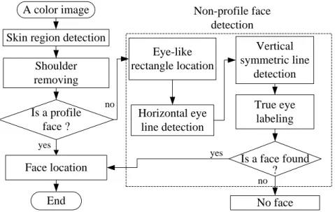
various poses and environments. Fig. 1.1 shows the block diagram of the proposed
face detector. First, we use skin colors to extract candidate skin regions. Next, shape
information is used to judge whether a skin region contains a shoulder part. If yes, a
skin projection based method will be applied to remove it and the head part is labeled
as a face candidate for further processing. For each face candidate, a set of geometric
constrains are firstly applied to judge if the face candidate is a profile face. If no,
some eye-like rectangles are first extracted. Then, based on these eye-like rectangles,
a horizontal eye line and a vertical symmetric line are located to judge if the face
A color image Skin region detection
Is a profile face ? Face location Eye-like rectangle location Vertical symmetric line detection End Non-profile face detection Shoulder removing Is a face found No face True eye labeling Horizontal eye line detection no yes no yes ?
Fig. 1.1. The block diagram of the proposed face detector.
1.3 SYNOPSIS OF THE DISSERTATION
The rest of the dissertation is organized as follows. Chapter 2 describes the
proposed horizontal eye line detection and eye-like region detection method. The
face-pose identification method and face detection method with different poses under
vary environment are proposed in Chapter 3. Some conclusions and future research
CHAPTER 2
A NOVEL METHOD FOR
HORIZONTAL EYE LINE DETECTION
UNDER VARIOUS ENVIRONMENTS
In this chapter, we will propose a method to extract the horizontal eye line of a
face and some eye-like regions under various environments. It contains several steps.
First, we will use skin colors to extract candidate skin regions. Next, an eye-like
region detector based on intensity and color information will be provided to explore
all possible eye-like regions in each candidate skin region. A lighting distribution
based algorithm will then be presented to remove some false eye regions. Finally,
based on the extracted eye-like regions, the horizontal eye line for a candidate skin
region can be located using the gray level distribution of the skin region.
2.1 INTRODUCTION
In a drowsy driving warning system, driver’s mental condition can be revealed
by measuring the eye movement from the eye location [1]. How to locate the eyes of a
driver under extreme lighting condition is an important issue for a successful
intelligent transportation system. Detecting the eye line can help locate eyes.
detection has been studied for more than 20 years, developing a human face detector
under various environments is still a challenging task. Some factors make face
location difficult. One is the variety of colored lighting sources, another is that facial
features such as eyes may be partially or wholly occluded by shadow generated by a
bias lighting direction; others are races and different face poses with/without glasses.
In order to overcome this problem, Hjelmas and Low [2] have presented an extensive
survey of feature-based and image-based algorithms for face detection. In
feature-based methods, the most widely used technique is skin color detection based
on one of the color models. Most Image-based approaches are based on
multiresolution window scanning to detect faces at all scales, making them
computationally expensive. Also, Yang [3] classifies the approaches into four
categories: knowledge-based, feature invariant, template matching, and
appearance-based and address one of the difficulty of face detection is lighting source
varies significantly. Several methods [4-18] had been proposed by now. Some [4-6]
use eigenface, neural network and support vector machine (SVM) to detect faces of
restricted poses under normal lighting condition. Chow [7] proposed an approach to
locate facial features (such as eyes, eyebrows) by using an eigenmask under different
lighting conditions. However, the method fails to locate the facial features for some
and contour information to locate face in a plain background and normal lighting
condition. However, it is difficult to detect the predefined shape of a face in a complex
background and various lighting conditions. Wu et al. [9] proposed an algorithm to
locate face candidates using eye-analogue segments information. The algorithm
would fail when a person wears glasses. Some methods [10-12] use mosaic, edge and
mathematical morphology to detect eyes, however, these methods would fail to locate
eyes when a face is under a poor lighting condition (such as bias-light source). Wang
[13] proposed a boosted based algorithm to detect a face. But the training phase of the
method is time consuming and it is only designed for frontal face. Shih [14] proposed
a color based method shows reasonable performance in terms of detection rate.
However, the detection would fail under extreme lighting condition.
As mentioned above, extreme lighting conditions (such as colored lighting
source and bias lighting direction), different subject poses, glasses, races, and
complex background are factors to make face detection difficult. To solve the problem
caused by these factors, we will propose a method to extract the horizontal eye line of
a face and some eye-like regions under various environments. The extracted eye line
and eye-like regions can be further used to help extract the true positions of eyes and
2.2 THE PROPOSED METHOD
The proposed method contains several steps. First, we will use skin colors to
extract candidate skin regions. Next, an eye-like region detector based on intensity
and color information will be provided to explore all possible eye-like regions in each
candidate skin region. A lighting distribution based algorithm will then be presented to
remove some false eye regions. Finally, based on the extracted eye-like regions, the
horizontal eye line for a candidate skin region can be located using the gray level
distribution of the skin region.
2.2.1 The Proposed Skin Region Detector
In several face detection systems [15], skin color plays a major role for
segmenting face regions from an image. There are several color models utilized to
label pixels as skin, these include RGB, HSV and YCrCb color spaces [16-18]. Since
a face image is usually taken under unpredicted lighting conditions, RGB color-model
is sensitive to light and unsuitable for representing skin color. In YCbCr model, Cr
represents the red degree [15]. Since human skin color tends to red, we will adopt
2.2.1.1 Skin Region Extraction
Some skin detectors [14, 15] work on skin-color distribution modeling. Different
illumination levels such as indoor, outdoor, highlight and shadows will change the
color of skin. However, the size of the training set and variety of samples used in the
training may be impact on the skin detector performance [15]. That means the trained
skin model may be required extensive training and fine tuning to archive an optimal
performance for different training samples. In this dissertation, the skin detector
works on explicit skin-color space thresholding.
As mentioned above, human skin color tends to red despite the race, we will use Cr
value to determine whether a pixel is skin or not. If a pixel’s Cr value is larger than a
predefined threshold, then it will be considered as a skin pixel. In this dissertation, a
threshold Crth1 is adopted to bound skin color. On the other hand, the Cr value for skin
pixels will be lowered under a high lighting with blue color biased source
environment, another lower threshold Crth2 will also be used. That is, for an input
image, we first use Crth1 (here, 142 is used) as threshold to get candidate skin regions.
Then, for the same input image, we use Crth2 (here, 132 is used) as threshold to get
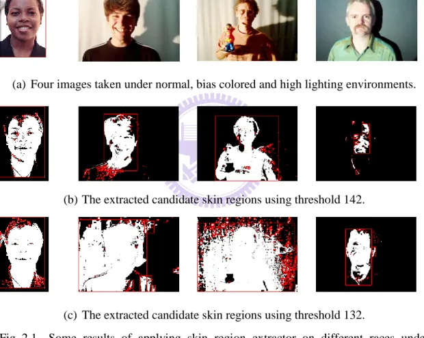
another candidate skin regions. Fig. 2.1 shows some results of applying the skin
region extractor on different racial faces. From this figure, we can see that whatever
pixels). After skin pixels are extracted, those connected skin pixels are grouped to
form a set of candidate skin regions, each region is bounded by a red rectangle (see
Figs. 2.1(b) and 2.1(c)). From Fig. 2.1, we can see that some extracted candidate skin
regions are not true skin. In the next section, we will present a filter to remove some
false skin regions.
(a) Four images taken under normal, bias colored and high lighting environments.
(b) The extracted candidate skin regions using threshold 142.
(c) The extracted candidate skin regions using threshold 132.
Fig. 2.1. Some results of applying skin region extractor on different races under various lighting environments.
2.2.1.2 Skin Region Filter
The skin region filter is designed to remove false skin regions based on four
used to remove several false regions. The detail is described as follows.
(1) Size: A candidate skin region will be removed if the width or height of its bounding rectangle is less than a threshold Sth. In this dissertation, we set Sth to be
15 (see Figs. 2.2(b) and 2.2(d)). On the other hand, if the width of its bounding rectangle is larger than a half of the input image width, the region will also be removed.
(2) Shape: In general, the shape of a face should be like an ellipse. Thus, if a region looks like a horizontal or vertical thin bar, it should be removed (see Fig. 2.2(b)). Note that if a region with Hs/Ws Vth, it is considered as a vertical thin bar. On
the other hand, if a region with Ws/ Hs Hth, it is considered as a horizontal thin
bar. Here, Hs and Ws are the height and the width of a region, and in the
dissertation, we set Vth to be 2.5 and Hth to be 0.5.
(3) Uniform-Content: A uniform content region should not be a face due to that the eyes and eyebrows are in face. Thus, if the standard derivation of the gray values in the bounding rectangle of a candidate skin region is less than a predefined threshold Uth (10), the region will be removed (see Fig. 2.2(f)).
(4) Geometric relation: If two candidate skin regions crossover and the small one is less than a half of the big one, then the small one is removed (see Fig. 2.2(g)). On the other hand, if a small region is totally covered by another big region, then both regions are preserved (see Fig. 2.2(g)). For this case, in the later process, the small one is first used to detect the eye line. If an eye line is found, the detection for the big one will be skipped.
Vertical shape region
Small size regions
(a) A face image. (b) Candidate skin regions using 132 as threshold.
Small size regions
(c) The result of removing regions of small sizes and improper shapes in (b).
(d) Candidate skin regions using 142 as threshold.
(e) The result of removing small regions in (d).
(f) The result of merging (c) and (e) and imposed on (a).
(g) The result of removing uniform content regions and cross over regions in (f). Fig. 2.2. Some examples for illustrating the skin region filter.
2.2.2 The Proposed Eye-Like Region Detector
In this section, we will provide a method to extract eye-like regions from those
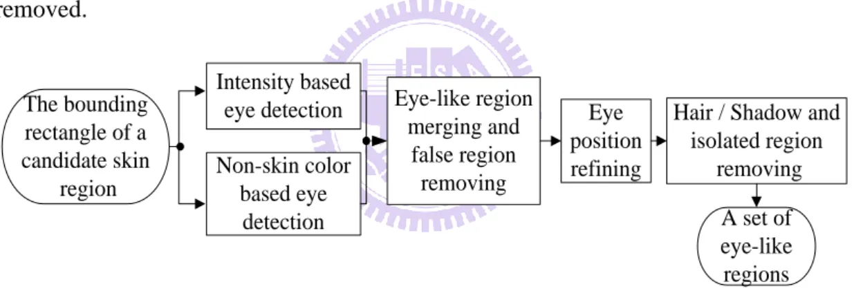
remaining candidate skin regions. Fig. 2.3 shows the block diagram of the proposed
eye-like region detector. First, based on intensity and skin color information, some
eye-like regions are extracted. Next, some false regions are removed. Since the true
eye may not be located in the center of the eye-like region, a refining algorithm is
presented to adjust the eye-like region. Finally, some false eye-like regions appearing
in hair or shadow part will be removed, and isolated eye-like regions are also
removed. A set of eye-like regions The bounding rectangle of a candidate skin region Intensity based eye detection Non-skin color based eye detection Eye-like region merging and false region removing Eye position refining
Hair / Shadow and isolated region
removing
Fig. 2.3. The block diagram of the eye-like region detector.
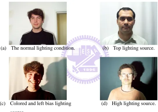
In [7], luminance contrast and eye shape are used to detect an eye. However, under
various lighting environments, unpredicted shadow appearing on face makes eye
detection difficult. Fig. 2.4 shows some face images taken under various lighting
environments. To treat this problem, we use two fundamental eye properties to extract
eye-like regions. The first property is that the pupil and iris’s gray values are lower
provided to locate eye-like regions in the bounding rectangle of each candidate skin
region. The second property is that under non-colored lighting source condition, the
eye color will be very different from skin color. Based on this property, we consider
those small non-skin color regions in the bounding rectangle of a candidate skin
region as eye-like regions.
(a) The normal lighting condition. (b) Top lighting source.
(c) Colored and left bias lighting source.
(d) High lighting source.
Fig. 2.4. Subjects taken under various lighting environments.
2.2.2.1 Intensity Based Eye-Like Region Extraction
After extracting candidate skin regions, an intensity based detector will be first
provided to extract eye-like regions from the bounding rectangle of each candidate
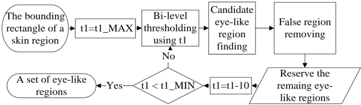
The bounding rectangle of a skin region t1=t1_MAX Bi-level thresholding using t1 Candidate eye-like region finding False region removing Reserve the remaing eye-like regions t1=t1-10 t1 < t1_MIN A set of eye-like regions Yes No
Fig. 2.5. The flowchart of the intensity based eye-like region detector.
Based on the fact that the pupil’s gray value are lower than skin gray values, the
detector adopts a bi-level thresholding to get the eye-like regions. First, for a
candidate skin region, several different threshold values, t1, are used for bi-level
thresholding, the maximum and minimum of t1 are named as t1_MAX and t1_MIN,
respectively. t1_MAX is set as the average gray value of 10% pixels with maximum
gray values in the candidate skin region and t1_MIN is set to be the average gray
value of 5% pixels with minimum gray values in the candidate skin region. At
beginning, a bi-level threshold operator with t1_MAX as the initial threshold is
applied to extract eye-like regions, and then the operator is applied literately with t1
reduced by a value Ith (here, 10 is used) each time until t1 reaches t1_MIN. Fig. 2.6
shows an example for evaluating t1_MAX and t1_MIN, and the result of applying the
t1_Min t1_Max t1=146 t1=86 t1=56
(a) A face region.
(b) The histogram of detected gray pixels within the skin region.
(c) Bi-level thresholding results of (a) using different thresholds.
Fig. 2.6. An example of the bi-level thresholding results.
After applying a bi-level thresholding operator at each time, every resulting black
region is considered as a candidate eye-like region. However, some of these black
regions are false ones. Here, we provide three filters to remove these false eye-like
regions. One is geometric filter, which is used to remove too small or too large regions.
A black region with size less than Sth2 (here, Sth2 is set as 5x5) or its width (height)
larger than Sth3 (here, we set Sth3 to be 1/4 skin region width) will be removed. One is
statistical filter, if the standard derivation of the gray values of an eye-like region is
lower than a predefined threshold, the region is considered as a false eye-like region
and then removed. Here the threshold we chose is 10. From the structure of an eye, we
can see that the iris and pupil’s gray levels are lower than skin. Based on this property,
the third filter called projection filter is provided to remove each black region with its
average gray value larger than that of the upper or lower neighboring areas. A
of the highest peak above or below the position, we removed the region. Fig. 2.8
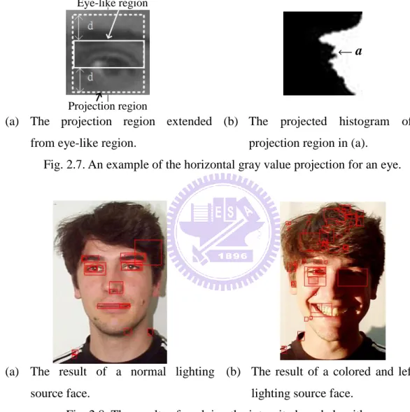
shows the final result of applying the intensity based eye-like region detector to a face
image, each extracted eye-like region is enclosed by a red rectangle.
Eye-like region
Projection region
a
(a) The projection region extended from eye-like region.
(b) The projected histogram of the projection region in (a).
Fig. 2.7. An example of the horizontal gray value projection for an eye.
(a) The result of a normal lighting source face.
(b) The result of a colored and left bias lighting source face.
Fig. 2.8. The results of applying the intensity based algorithm.
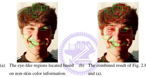
2.2.2.2 Non-Skin Color Based Eye Detector
Under a very low lighting environment, an eye-like region extracted by intensity
information to locate eyes. First, non-skin color regions within a candidate skin region
are considered as eye-like regions. The three false eye-like region filters described in
Section 3.1 are then used to remove some false regions. Fig. 2.9(a) shows the result of
applying the non-skin color based eye detector. Each eye-like region is enclosed by a
green rectangle. From this figure, we can see that the left eye was precisely located.
Fig. 2.9(b) shows the combined result of Fig. 2.8(b) and Fig. 2.9(a).
(a) The eye-like regions located based on non-skin color information.
(b) The combined result of Fig. 2.8(b) and (a).
Fig. 2.9. The result of applying the proposed intensity and non-skin color based eye detectors.
2.2.3 False Eye-Like Region Removing
The obtained eye-like regions still contain some false regions; we can classify these
regions into five classes: overlapped, hair reflecting, beard/clothes, isolated, and
forehead-hair (see Fig. 2.10). In the following, we will provide some procedures to
Hair reflecting Overlappe d Isolated / overlapped Beard / clothes Hair reflecting Forehead -hair Overlapped Beard / clothes
(a) An example to show four classes of false eye-like regions.
(b) Another example to show forehead - hair class.
Fig. 2.10. Five false region classes.
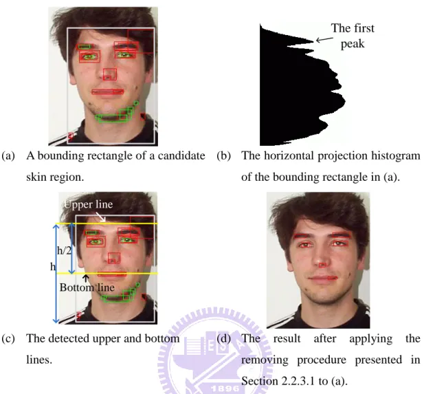
2.2.3.1 Overlapping/ Hair Reflecting/ Beard/ Clothes False Region Removing
For the overlapping class, if one eye-like region totally covers a small eye-like
region, the covering region is removed. To remove hair reflection regions, first, a
horizontal gray level projection histogram (see Fig. 2.11(b)) is created. Then, the first
peak location from the top of the projection histogram is defined as an upper line
which usually indicates the forehead. Each eye-like region intersecting the upper line
is removed. For the beard/clothes class, we first define a bottom line with distance h/2
from the upper line, where h is the distance between the upper line and the bottom of
the skin region. Then all eye-like regions below the line are removed. Fig. 2.11(d)
The first peak
(a) A bounding rectangle of a candidate skin region.
(b) The horizontal projection histogram of the bounding rectangle in (a).
h/2
Upper line
Bottom line h
(c) The detected upper and bottom lines.
(d) The result after applying the removing procedure presented in Section 2.2.3.1 to (a).
Fig. 2.11. The result of applying the false eye-like removing procedure.
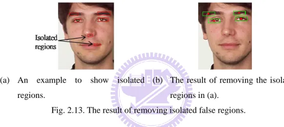
2.2.3.2 Eye Position Refining And Isolated False Region Removing
For a non-rotated human face, an eye pair should be located at a near-horizontal
line. Thus for an eye-like region, if we can not find another region at its left or right,
then this region is called isolated region and should be removed. However, under
various environments, a true eye may not be located at the center of the extracted
eye-like region (see Fig. 2.12(a)), we are then unable to know where the eye is. In
order to treat this problem, we provide an eye position refining method to locate the
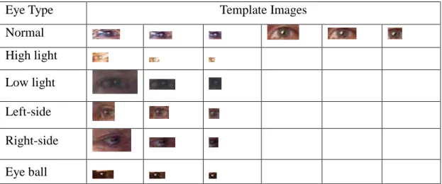
into three classes according to the lighting condition: normal, high light and low light.
Next, one image is selected randomly from each class. Considering the effect of
glasses, the normal class has two images selected with/without wearing glasses. For
each image, three templates are extracted (see Table 2.1). An eye area including eyelid
is taken as the first template. In the first template, an area only containing eye is then
taken as the second template. In the second template, an area only containing eye ball
is taken as the third template. After obtaining the twelve templates, we use each
template to mask each eye-like region by sliding the template pixel by pixel in the
region to find the best matched area for each class. Covariance is used to measure the
similarity. If an eye-like region with the located eye center does not lie in the true eye,
we take three new templates from the image containing the region using the previous
method. The procedure is repeated until all eye-like regions are processed. After the
procedure is finished, we find that nine new templates (see Table 2.1) belonging to
three new classes are extracted. These three new classes are left-side (the eye sees the
left side), right-side (the eye sees the right side) and bias lighting. Since the images in
HHI have different face sizes, the extracted templates will also have different sizes.
After we make the eye templates, a mentioned similarity matching procedure is
adopted to find the best matched area for testing image. We use the similarity function
n B b A a B A n i mean i mean i
1 ) )( ( ) , cov( , (2-1)where A[a1,a2,...,an] and B[b1,b2,...,bn] are two areas, and Amean and Bmean
are the mean values for each area. Thus, we can obtain six best matched areas for each
eye-like region. Then the center of the best matched area with the highest Cb/Cr value
(the most possible non-skin area) is considered as the best eye center in the eye-like
region (see the red points in Fig. 2.12(b)). Finally, all eye-like regions are refined to
be a wh region centering at the best eye center. In the dissertation, we set w to
30, h to 10 (see the green rectangles in Fig. 2.12(b)). After an eye-like region is
refined, we judge if it is an isolated region. If yes, the region will be removed. Fig.
2.13(b) shows the result of removing those refined isolated false regions.
Table 2.1 The templates for six eye classes.
Eye Type Template Images
Normal High light Low light Left-side Right-side Eye ball
(a) An example to show an eye not located at the center of the eye-like region.
(b) The result of applying the eye position refining procedure to (a).
Fig 2.12. The result of applying the eye position refining procedure.
(a) An example to show isolated regions.
(b) The result of removing the isolated regions in (a).
Fig. 2.13. The result of removing isolated false regions.
2.2.3.3 Forehead-hair false regions removing
Before describing the proposed forehead-hair false region removing algorithm, we
will define the bounding rectangle for a face. Let R be the minimum rectangle
containing all eye-like regions, then R is expanded in the vertical direction to form a
square rectangle (see Fig. 2.14). The square rectangle is defined as the bounding
(a) The minimum rectangle containing all eye-like regions.
(b) The expanding result of (a).
Fig. 2.14. An example to illustrate the bounding rectangle of a face.
In general, pixels in hair or shadow regions caused by a bias lighting have lower gray
levels than pixels in a face. Based on this property, we find that if the bounding
rectangle of a face contains a part of lower gray region (hair or side shadow), its
gray-level histogram, h(x), will be a bi-model distribution; else the histogram will be a
uni-model distribution (see Fig. 2.15). To distinguish these two models, an average
probability horizontal line (APL) Y = T with
255 0 ) ( 256 1 T x x
h is first defined. If the
number of the intersection line segments between the APL and the histogram is two, a
bi-model distribution is identified (see Fig. 2.15(a)). Otherwise, if only one line
segment exists, a uni-model distribution is identified (see Fig. 2.15(b)). For a face
bounding rectangle, those eye-like regions appearing in the hair area should be
removed. Based on the above discussion, a procedure is proposed to remove
forehead-hair false regions. To identify the hair part, we set the initial bi-level
threshold t0 as average gray value of the face rectangle for a bi-model histogram. If
255 0 ) ( % 5 ) ( min x x h t ACC t with
t x x h t ACC 0 ) ( )( . The pixels with gray levels
less than t0 are labeled as black pixels. However, the threshold may be improper such
that over-segmentation or under-segmentation (see Fig. 2.16) will occur. To treat this
problem, the threshold t0 will be adjusted according to the following procedure. After
applying the bi-level thresholding, if no two eye-like regions contain over Oth (30%)
black pixels, an over-segmentation is detected (see Fig. 2.16(b)). The t0 should be
adjusted to be larger. The adjustment rule is to take the nearest right valley to the
current t0 on the histogram as a new threshold t0. If there is no valley is found, then
the t0 will be adjusted by increasing a threshold value (Nth), here Nth is set to be 5.
Bi-model (a) A bias lighting face and its corresponding histogram.
Uni-model (b) A normal lighting face and its corresponding histogram.
(a) Original image. (b) An over-segmentation obtained after applying the threshold process to (a).
(c) Original image. (d) An under-segmentation obtained after applying the threshold process to (c). Fig. 2.16. Two examples to show the over-segmentation and under-segmentation.
On the other hand, if all eye-like regions are located in a big black area, an
under-segmentation is detected (see Fig. 2.16(d)), t0 will be refined to smaller. The
adjustment rule is to take the nearest left valley to the current t0 on the histogram as a
new threshold t0. If there is no valley was found, then the t0 will be decreased by Nth.
The above procedure is repeated until no over or under segmentation occurs. In order
to prevent a dangling situation, any used valley will be removed to avoid reusing.
Then the bi-level thresholding operator with the final threshold is applied to identify
the dark regions in the face bounding rectangle (see Fig. 2.17(b)). If a dark area is hair,
it should be large in the face bounding rectangle. If a dark area is iris, it should be
small. So, for a dark region with area larger than
4 1
consider it as a hair region, and all eye-like regions in the hair region are removed. In
addition, if a dark region has the ratio of the height over the width larger than a
threshold 2.5, we will remove the region. On the other hand, since the iris and eyelids
have lower gray level than the other part of an eye, if an eye-like region contains less
than 3% dark pixels, the region is also removed. Note that any eye-like region
locating at the shadow part will also be removed by the above procedure (see Fig.
2.17(c)). To resume these regions, we use a previously mentioned fact if an eye is
found, then the other eye should be found at its right side or left side. For each
remaining eye-like region, R, we first draw three lines, L1, L2 and L3, passing
through the center of R. L1 is a horizontal line, the angles between L1 and L2 (or L3)
is a predefined angle Ath (here, 10 is used) (see Fig. 2.18(a)) for a bi-model
histogram face. Then a bounded range, BR, is defined to be the area bounded by L2
and L3. Based on the bounded range, all eye-like regions in the bounded range
removed by the forehead-hair false region removing procedure will be got back (see
Fig. 2.18(b)). Now the remaining eye-like regions are used to form a new bounding
rectangle (see the dotted rectangle in Fig. 2.18(b)) which will be used to determine the
(a) The eye-like regions before applying the removing procedure.
(b) The result of applying the bi-level threshold to (a).
(c) The result of removing the forehead - hair false regions in (b).
Fig. 2.17. The result of applying the forehead-hair false region removing procedure.
0 10 0 10 L2 L1 L3 R w w/4
(a) The bounded ranges for resuming the removed eye-like regions in the shadow area of a face.
(b) Three eye-like regions (marked by white rectangles) got back.
Fig. 2.18. An example to explain the eye-like region resuming procedure.
2.2.4 The Proposed Horizontal Eye Line Detector
In this section, we will propose a novel eye line detection algorithm. Because
eyes and eyebrows are regions with low gray-level, their locations will correspond to
algorithm can be reduced as a valley finding procedure on the horizontal gray value
projection histogram. In the valley finding procedure, all valleys are taken first, then
the small valleys with value smaller than a threshold Dth (here, we set Dth to be 3) will
be removed. If some valleys are located at similar locations with distance between
two neighboring ones smaller than a threshold Bth (here, Bth is set to be 3), the deepest
valley will be kept, others are discarded.
The detail is described as follows. For a given bounding rectangle of a face, if there
is only one valley in the projection histogram and there is a pair of eye-like regions
near the valley (see Fig. 2.19(a)), then the horizontal line (the green line in Fig.
2.19(a)) is defined as the line passing through the vertical middle location between the
two eye-like regions. If there are two valleys, and if the distance between these two
valleys is less than a threshold and there are at least one pair of eye-like regions near
the two horizontal lines passing through these two valleys, respectively, then the
upper one (the red line in Fig. 2.19(b)) is considered as the eyebrow line and the other
(the green line in Fig. 2.19(b)) is the eye line. If there are 3 or 4 valleys, we will
execute the following procedure (called procedure A). First, we define the distance
between the first and second valleys as D1 and between the second and third valleys
Condition 1: D1s1D2. Condition 2: D1s2D2.
Note that s1 and s2 are set as 1.2 and 3.0 in the dissertation.
If valleys satisfy Condition 1 and there exist two eye-like regions near the second
valley line, then the second valley line (the green line in Fig. 2.19(c)) is considered as
eye line. On the other hand, if Condition 2 is satisfied and there exist two horizontal
eye-like regions near the first valley line, then the first valley line (the green line in
Fig. 2.19(d)) is considered as the eye line. If both conditions are not satisfied, we will
apply procedure A described above to the next three valleys (the second, third and
fourth). If no eye line is found, we conclude that the region is not a face. If an eye line
is found, any eye-like region which distance from the eye line larger then 1.5 height of
the eye-region will be removed. Then, the remaining regions will be used to outline a
face rectangle where the left/right position is the most left/right region. The top
position of the rectangle is defined as the upper location of the most top region from 3
height of an eye-like region. And the height of the rectangle is defined as 1.3 width of
(a) Only one valley case. (b) Two valleys case.
(c) D1s1D2 with two eye-like regions near the second valley line.
(d) D1s2D2 with two eye-like regions near the first valley line. Fig. 2.19. Some examples for the horizontal projection.
2.3 EXPERIMENTAL RESULTS
In order to show the effectiveness of the proposed method, we apply the
proposed method to HHI face database [19] of 206 images (see Fig. 2.20) and
Champion face database [20] of 227 images (see Fig. 2.21). We also collect some
other images from Internet, MPEG7 video clips, PIE database [21] to evaluate the
performance. These contain face images of different racial persons under different
kinds of lighting conditions (such as overhead, side and color lightings). Since one of
our main applications of the method is for a drowsy driving warning system and in
most cases, a driver’s head position is usually frontal or near profile. Since the head is
rarely in-plane rotated when people are drivning, in dissertation only detect the
implemented by Java language on a laptop with Pentium(R) M processor 1.4 G Hz
CPU. In Fig. 2.21, some successful results of applying our method to some faces with
different skin colors. The successful results for faces with different poses and eye
glasses are shown in Fig. 2.20. Even there is shadow on a face; the eye line can also
be detected (see Fig. 2.22).
Fig. 2.20. A part of images from HHI face database with different poses and eye-glasses.
Fig. 2.21. A part of images from Champion face database with different skin colors.
Fig. 2.22. The detection results for persons with shadows and various lighting sources on their faces.
If the detected eye line is located under eye brow and near eyes, we consider it to be a correct detection; otherwise it is an error detection. The tolerance value is the height of an eye-like region. If no horizontal eye line is detected for a face image, we call it a missing detection. Fig. 2.23 shows the successful detection results for a set of images from the Internet, MPEG7 video clips and PIE database images. For HHI database, the correct detection rate is 95.63% and the correct detection rate on Champion database is 94.27%. Fig. 2.24 shows the error and missing detection results.
Fig. 2.23. The detection results of face images collected from the Internet, MPEG7 video clips and PIE database.
CHAPTER 3
A NOVEL FACE DETECTION METHOD
UNDER VARIOUS ENVIRONMENTS
In this chapter, we will propose a method to detect a face with different poses
under various environments. It consists of three phases: profile feature extraction,
non-profile face detection and the true eye locating.
3.1 INTRODUCTION
Detecting a face from an image is the first step for face applications. Even it has
been studied for many years; detecting a face under various environments is still a
challenge work. Some factors make face detection difficult. One is the variety of
colored lighting sources, another is that facial features such as eyes may be partially
or wholly occluded by shadow generated by a bias lighting direction; others are races
and different face poses with/without glasses. Several methods [4-18] had been
proposed to detect faces. Some [4-6] use eigenface, neural network and support
vector machine (SVM) to detect faces of restricted poses under normal lighting
properties are used to extract the facial features and applied to verify a face. Chow et
al. [7] proposed an approach to locate a face candidate under different lighting
conditions and then applied an eigenmask based method to verify the face. However,
these methods fail to locate faces with some kinds of poses (such as near-profile and
profile face). Shin and Chuang [8] uses shape and contour information to locate face
in a plain background and normal lighting condition. However, it is difficult to detect
a face in a complex background and various lighting conditions. Wu and Zhou [9]
proposed an algorithm to locate face candidates using eye-analogue segment
information. The algorithm would fail when a person wears glasses. Some methods
[10-12] use mosaic, edge and mathematical morphology to detect eyes, however,
these methods would fail to locate eyes when a face is under a poor lighting
condition (such as bias-light source).
3.2 THE PROPOSED METHOD
As mentioned above, various lighting conditions, different head poses, glasses,
races, and complex background are factors to make face detection difficult. To solve
these problems, we propose a method to detect a face with/without glasses under
various poses and environments. Fig. 3.1 shows the block diagram of the proposed
information is used to judge whether a skin region contains a shoulder part. If yes, a
skin projection based method will be applied to remove it and the head part is
labeled as a face candidate for further processing. For each face candidate, a set of
geometric constrains are firstly applied to judge if the face candidate is a profile face.
If no, some eye-like rectangles are first extracted. Then, based on these eye-like
rectangles, a horizontal eye line and a vertical symmetric line are located to judge if
the face candidate is a non-profile face.
A color image Skin region detection
Is a profile face ? Face location Eye-like rectangle location Vertical symmetric line detection End Non-profile face detection Shoulder removing Is a face found No face True eye labeling Horizontal eye line detection no yes no yes ?
Fig. 3.1. The block diagram of the proposed face detector.
The remaining of this chapter is described as follows. In Section 3.2.1, a shape
based algorithm is proposed to identify a profile face. Section 3.2.2 presents an
algorithm to detect a non-profile face. Section 3.2.3 provides the true eye locating
3.2.1 Profile Detection
In this section, we will provide a method to determine if an image contains a
profile face. First, the skin region detector proposed by Jing and Chen [22] is
adopted to extract skin regions from an input image. Fig. 3.2 shows the extracted
results from some face images with different poses taken under various lighting
environments. Note that some pixels in clothes with color similar to skin are also
labeled as skin. In the following, we will provide a method to remove these pixels.
(a) Three images taken under various lighting environments.
(b) The extracted skin regions (white pixels) using Jing-Chen skin region detector. Fig. 3.2. Some results of applying Jing-Chen skin region extractor.
3.2.1.1 Shoulder Removing Procedure
Fig. 3.3 shows an example of two men, one in Fig. 3.3(a) wears a T-shirt of
3.3(c) and 3.3(d) show the results of applying Jing-Chen method to Figs. 3.3(a) and
3.3(b), respectively. In Fig. 3.3(c), pixels on shoulder are labeled as skin pixels. Here,
a projection-based procedure is provided to remove the shoulder part.
(a) A man wearing a T-shirt of skin-like color.
(b) A man wearing a T-shirt of non skin-like color.
(c) The detected skin region of (a). (d) The detected skin region of (b).
Neck point
(e) The horizontal projection of (c). (f) The horizontal projection of (d). Fig. 3.3. An example showing two men wearing clothes with/without skin-like color.
First, we need to determine whether a skin region includes a shoulder part. In