The Development of Constraint Algorithms and
Real-time Smoothing for Pedestrian Indoor
Navigation with Smartphones
Jhen-Kai Liao, Kai-Wei Chiang, Zhi-Ming Zhou, Guang-Je Tsai, National Cheng Kung University, Taiwan
BIOGRAPHY
Jhen-Kai Liao is a Ph.D. candidate at the Department of Geomatics, National Cheng Kung University, Taiwan. His research interests include IMU calibration, integrated navigation system, mobile mapping, as well as indoor and smartphone navigation.
Guang-Je Tsai is a Ph.D. student at the Department of Geomatics, National Cheng Kung University, Taiwan. His research interests include Pedestrian Dead Reckoning and aiding algorithm.
Zhi-Ming Zhou is a Master student at the Department of Geomatics, National Cheng Kung University, Taiwan. His research focuses on navigation with smartphones and activity recognition.
Dr. Kai-Wei Chiang received his Ph.D. in Department of Geomatics Engineering, University of Calgary, Canada. He is currently a professor in the Positioning, Orientation and Integrated Navigation Technologies Lab, Department of Geomatics, National Cheng Kung University, Taiwan. ABSTRACT
Personal navigation technologies have been evolving rapidly because of the increasing popularity of smartphones and portable devices in recent years. This phenomenon has changed the developmental trend for pedestrian navigation with the use of available sensors. However, some considerations restrict the cost, accuracy and practicality of pedestrian navigation, especially in indoor environment without the Global Navigation Satellite System (GNSS).
The Inertial Navigation System (INS) has been widely used for vehicle navigation. However, INS is inappropriate for pedestrian navigation because the complicated motions of human body causes the dynamic misalignment between the body frame and pedestrian frame. Thus, the human motion will produce the large navigation error after the integration of acceleration and angle rate during INS mechanization with vibration noise and misalignment error.
Therefore, the INS mechanization requires the external measurements and constraints to improve the navigation
accuracy, especially for real-time pedestrian indoor navigation. In general, the loosely couple is an ideal form for aiding the INS mechanization by integrate the position and orientation. This study uses the position of control point as the update measurement in the extended Kalman Filter (EKF) to aid the INS mechanization without GNSS. The sources of those control points can be pre-surveyed control points, map database, feature points and other Radio Frequency (RF) based indoor positioning technologies.
This study proposes the Walking Velocity Constraint (WVC) to enable the use of walking velocity from a pedometer and step length model to constrain the velocity of moving direction in the EKF. Moreover, the real-time smoothing is also implemented with the use of EKF and control points. The performances of proposed algorithms are verified for pedestrian indoor navigation with smartphones. The preliminary results show the proposed algorithms improve the performance of INS in real-time for pedestrian navigation in indoor environment significantly. Keywords: INS, smoothing, pedestrian indoor navigation INTRODUCTION
The smartphone can be an ideal device as a portable and indispensable pedestrian indoor navigator by provides the basic information for navigation with internal sensors such as GNSS chip, inertial sensors, magnetometer, camera, Wi-Fi and Bluetooth. In addition, the other motivation for developing navigation applications on smartphones is the high popularity of such devices over the world. Those characteristics of smartphones can reduce the cost of businesses for pedestrian indoor navigation products and their promotion. Moreover, the big data of location and users provide the fundamental information for Location-based Services (LBS) and facilitate personal marketing. Thus, the commercial opportunity for pedestrian indoor navigation is becoming mature owing to a large number of available equipment and users. The technology of pedestrian indoor navigation with smartphones and portable devices has become increasingly important in recent years.
Indoor navigation technology has been developed for nearly 20 years which has evolved to numerous variants from its original form based on different theories and
equipment [1-4], as shown in Table 1 [3]. The crucial issues are how to achieve the necessary accuracy without the GNSS as well as to adapt to human motion for pedestrian indoor navigation.
Table 1: Summary of indoor navigation technologies [3]
The major principle of traditional indoor navigation technologies relies on the measurement of the signals from additional transmitters and receivers, such as the method of Time of Arrival (ToA) and Angle of Arrival (AoA). These methods provide reliable performance for pedestrian indoor navigation. However, they are inconvenient and require additional cost because it needs to set up additional equipment for the user and environment. These kinds of
radio-based positioning systems are suited to applications where there are a relatively-large number of users within a relatively-small area [5]. The accuracy affected by the quality of signal, density of additional equipment and the environmental factors.
Wi-Fi and Bluetooth are two of the most popular indoor navigation technologies. Although they can implement with the methods such as ToA and AoA, the Wi-Fi positioning commonly uses the fingerprinting with a training database as well as the Bluetooth positioning generally provides the approximate location at near place when sensing the signal. Thus, the factors of their accuracies are similar to the mention above because of the signal based theory.
The camera-based method is also a traditional indoor navigation technology with long history. However, for the purposes of seamless and real-time application, the feature recognition and image matching are the challenges of camera-based navigation. The camera-based method requires an image database and server to derive a matching solution for positioning. Such derivation is time consuming and does not allowed any change of the environment. The accuracy depends on the quality of image as well as the recognition and matching algorithms.
The Pedestrian Dead Reckoning (PDR) estimates two-dimensional position by using a pedometer and heading sensor which can reduce the error caused by the pedestrian. Because the model simplifies the 3D world to 2D world, in which the impact of gravity is not applied in the PDR equations. In other words, the impact of gravity projection
on horizontal components in INS is eliminate in PDR by non-integral calculation for low cost sensor. Therefore, the PDR has become one of the most popular methods used for pedestrian navigation.
However, the PDR cannot provide height information without using a barometer, and its orientation accuracy is similar to INS that restricted by the performance of gyro or magnetometer. The gyro is strongly affected by human motion because of the integration of system with vibration noise and dynamic misalignment between body frame and pedestrian frame. On the other hand, the magnetometer is strongly affected by the change of environmental magnetic field which caused by the magnetic material and environmental change. Furthermore, step length models generally use empirical formula, which are incapable to perfectly fitting individual characteristics. The use of tuning parameters for enhanced accuracy in post-processing is inconvenient for real-time application. The step length can vary by as much as 40% among different pedestrians, even when they are walking at the same speed, and by up to 50% across the range of walking speeds of an individual [2]. Even the step length calibration may be accompanied by a risk that demonstration systems have better performance than a production system because of the uncertainty of the coefficients [5]. The PDR suffers similar positional drift to the INS mechanization because of the accumulated impact of inappropriate step length model as well as heading estimation. Therefore, the PDR system is likely to require occasional position corrections from an external (absolute) positioning system to maintain stable performance [2], which also similar to INS.
The INS navigation technology is usually integrated with the GNSS. This method utilizes mechanization equations to estimate the position and orientation to aiding GNSS for seamless vehicle navigation in the outdoor environment with possible satellite outages. The algorithms of INS/GNSS integration are already quite mature and employ various methods to adapt to different environments for practical applications. However, such system is inappropriate for pedestrian navigation because human motion is far more extensive than the motion of moving vehicles. The vibration and dynamic misalignment caused by pedestrians produce the rapid drift of navigation error after the integration, especially for low grade sensors. The INS allows the change of environment and it doesn’t require the database and training process. It can reduce or even remove the requirement of additional equipment for the user and environment. In addition, INS provides the continuously real three dimension solution of position without barometer, as well as provides the orientation with the attitude information. Table 2 shows the characteristics and requirements of recently mainstream indoor positioning technologies. The requirement of additional infrastructures means the need of equipment such as wireless access point, transmitter and receiver.
Table 2: Popular indoor positioning technologies
According to Tables 1 and 2, indoor navigation technologies have different levels of accuracy depending on the required equipment and applicable conditions. Thus, the integration of different methods would be a stable solution to obtain the higher cost-performance ratio for practical real-time applications. EKF is often used in multi-sensor integrated estimation [6, 7]. This study uses EKF as the main estimator for INS to integrate the different sensors inside the smartphone and the position from other positioning technologies to provide the optimal estimation for pedestrian indoor navigation. In addition, the sources of those control points can be pre-surveyed control points, map database, feature points and other Radio Frequency (RF) based indoor positioning technologies.
The Non-holonomic Constraint (NHC) and Zero Velocity Update (ZUPT) are common constraints in the INS/GNSS integrated navigation system for vehicle applications [8]. The ZUPT assumes no velocity in three directions of a vehicle when a vehicle is on stop. The sensor of smartphone is hold on hand which is hard to sensing the stance phase of every stride rather than the shoe-mounted IMU, so the ZUPT was implemented when the user standing on the control points in this study. The NHC assumes that the lateral and vertical velocities of a vehicle do not exist. But NHC requires more stringent conditions for pedestrians because the undesirable lateral and vertical movement of human motion as well as there is no constraint on moving direction causes the navigation error drift quickly. However, the integration of INS and PDR can improve the accuracy of INS pedestrian navigation which proposed in [5]. This study used the body-mounted tactical grade IMU to develop the INS/PDR pedestrian navigation system. The measurement innovation is the difference between the step length from PDR and the position change from INS at each step. Thus, this study proposes the Walking Velocity Constraint (WVC) to enable the use of walking velocity from a pedometer and step length model to constrain the velocity of moving direction in the EKF since this inspiration.
The smoothing combines the estimated covariance from forward and backward EKF to provide more accurate estimation in post-processing [6]. The Rauch–Tung– Striebel (RTS), which is a fixed interval smoother is used in this study. However, smoothing in post-processing is inapplicable for real-time application because of the need to implement smoothing after filtering all data. Thus, the real-time smoothing (online smoothing) was proposed for
real-time application [9]. The basic concept is to perform smoothing in a short time when found the updating measurement which is the GNSS solution in the reference. The remaining time of filtering between the k and k+1 epoch is enough to implement smoothing during the real-time navigation based on the description of the reference. In other words, the smoothing can be implemented in real-time navigation when the amount of filtering data is small. This study modified the mode of real-time smoothing for pedestrian indoor navigation.
The performances of WVC, control point update and real-time smoothing are verified in this study. The preliminary results show the proposed concepts can improve the accuracy and stability of pedestrian indoor navigation for real-time applications significantly. In addition, the control points used in this study are provided by pre-surveyed points and beacons with the accuracy of centimeter and meter level. The control points can also from other indoor positioning technologies with available accuracy.
METHODOLOGY
Design of Core System
The EKF used in this study implements the control point update in the GNSS-hostile environment, as shown in Figure 1. The control point update used in the INS/GNSS integration scheme uses longitude, latitude, and height as the update measurements. The positioning technologies of those control points should provide the solutions with available accuracy and the same coordinate system. The smoothing will be implemented when the setting window is filled for real-time navigation.
Figure 1: Proposed EKF architecture with real-time smoothing and control point update
The state vector of EKF has 21 parameters as follows [10]: x = [δ𝑟1×3𝑛 δ𝑣1×3𝑛 δ∅1×3𝑛 𝑏1×3𝑎𝑐𝑐 𝑏1×3𝑔𝑦𝑟𝑜 𝑠1×3𝑎𝑐𝑐 𝑠1×3𝑔𝑦𝑟𝑜] (1)
where x is the state vector, δ𝑟1×3𝑛 is the position errors,
δ𝑣1×3𝑛 is the velocity errors, δ∅1×3𝑛 is the attitude errors, the
superscript n means the navigation frame. 𝑏1×3𝑎𝑐𝑐 and 𝑠1×3𝑎𝑐𝑐
are the biases and scale factor errors of accelerometer for three axes, 𝑏1×3𝑔𝑦𝑟𝑜and 𝑠1×3𝑔𝑦𝑟𝑜 are the biases and scale factor
The stages of predict and update are implemented the system estimation and measurement update in EKF respectively. The measurement includes the positions of GNSS and control points in this study. The control points will be the input of measurement update when the quality of GNSS is not available in the indoor and shelter environment. The models of predict and update stages are shown below:
Predict stage:
𝑥𝑘 = Φ𝑘−1𝑥𝑘−1 (2)
𝑃𝑘= Φ𝑘−1𝑃𝑘−1Φ𝑘−1𝑇 + Q (3)
where Φ is the transition matrix of the relationship between the states at k and k-1 epoch, P is covariance matrix of the state vector, and Q is the covariance matrix of the system noise.
Update stage:
𝐾𝑘= 𝑃𝑘𝐻𝑇(H𝑃𝑘𝐻𝑇+ 𝑅𝑘)−1 (4)
𝑥̂𝑘 = 𝑥𝑘+ 𝐾𝑘(𝑧𝑘− 𝐻𝑥𝑘) (5)
𝑃̂𝑘= (I − 𝐾𝑘H)𝑃𝑘(𝐼 − 𝐾𝑘𝐻)𝑇+ 𝐾𝑘𝑅𝑘𝐾𝑘𝑇 (6)
where K is the Kalman gain, H is the design matrix for update measurement, 𝑅𝑘 is the covariance matrix of
measurement noise at the k epoch, 𝑥̂𝑘 is the updated state
vector at the k epoch, and z is the measurement.
The estimated state feedback to the Inertial Measurement Unit (IMU) and INS mechanization to compensate the errors as well as replacing the previous state. Thus, the EKF design is preferred when low cost inertial sensors are applied which require frequent online calibration. In other words, the position update not only improving the quality of navigation states, but removing sensor errors as well. In fact, those deterministic sensor errors are supposed to be determined in laboratory [11]. However, the stabilities of those inertial sensors used in smartphones are not good enough for navigation purpose. As a result, the online calibration though the aiding information and EKF become feasible for real-time navigation with low grade sensors.
Proposed Constraint Algorithms
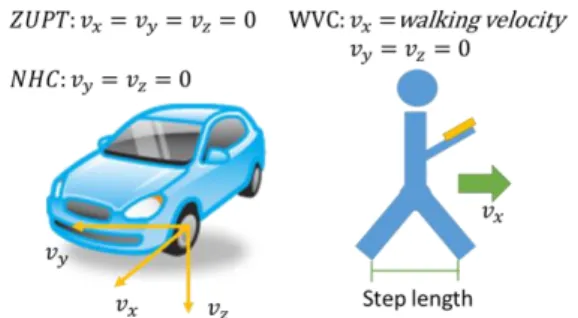
The NHC and ZUPT are used for the INS when the GNSS solution is not available in the GNSS-hostile environment. The NHC assumes that the velocities of a vehicle in the lateral and vertical directions should be zero when the vehicle keeps moving; The ZUPT assumes that the velocities of a vehicle in all directions should be zero when the vehicle is on stop [8]. In addition, the body frame should align to the vehicle frame. Figure 2 illustrates the assumptions of NHC and ZUPT. However, The NHC is insufficient to meet the pedestrian application because the slightly lateral and vertical movements of human motion are larger than vehicle case, and the walking vibration project to the moving direction cause the drift of navigation error after integral calculation. Thus, this study modifes the
weight of NHC for lateral and vertical direction. Furthermore, using the WVC to constrain the velocity of the moving direction by walking velocity.
Figure 2: The assumptions of NHC, ZUPT and WVC The pedometer and step length model can determine the walking velocity by step length and walking frequency at each step. The step length model used in this study is reference to the [12] which considers more individual parameters. However, the parameters of the step length model in this study are default from the reference because the purpose of this study is for real-time navigation which not allowed to adjust the parameters in post-processing. The equation of walking velocity is shown as follows:
𝑣𝑘𝑥= (0.7 + 𝑎(ℎ − 1.75) + 𝑏(𝐹𝑘−1.79)ℎ1.75 )𝑐 × 𝐹𝑘 (7)
where 𝑣𝑘𝑥 is the velocity of the moving direction at k epoch;
𝐹𝑘 is the walking frequency at the k epoch; a, b and c are
the tuning parameters of step length model; h is the height of pedestrian.
Real-time Smoothing
The RTS smoother, which is a fix-interval smoother, is usually employed for INS/GNSS vehicle applications in post-processing. The smoother estimates the optimal states by combining the forward and backward solutions of EKF. The estimated equations of the RTS smoother are given by [6]:
𝑥𝑘𝑠𝑚= 𝑥𝑘𝑢𝑝𝑑𝑎𝑡𝑒+ 𝐺𝑘(𝑥𝑘+1𝑠𝑚 − 𝑥𝑘+1𝑝𝑟𝑒𝑑𝑖𝑐𝑡) (8)
𝑃𝑘𝑠𝑚= 𝑃𝑘𝑢𝑝𝑑𝑎𝑡𝑒+ 𝐺𝑘(𝑃𝑘+1𝑠𝑚 − 𝑃𝑘+1𝑝𝑟𝑒𝑑𝑖𝑐𝑡)𝐺𝑘𝑇 (9)
𝐺𝑘 = 𝑃𝑘𝑢𝑝𝑑𝑎𝑡𝑒Φ𝑘+1𝑃𝑘+1𝑝𝑟𝑒𝑑𝑖𝑐𝑡 (10)
where G is the smoothing gain;𝑃𝑠𝑚,𝑃𝑢𝑝𝑑𝑎𝑡𝑒 , and 𝑃𝑝𝑟𝑒𝑑𝑖𝑐𝑡 are the smoothed, updated, and predicted
covariance matrixes, respectively; 𝑥𝑠𝑚, 𝑥𝑢𝑝𝑑𝑎𝑡𝑒, and 𝑥𝑝𝑟𝑒𝑑𝑖𝑐𝑡 are the smoothed, updated, and predicted state
vectors, respectively.
The application of real-time smoothing for the INS/GNSS integration with land-based vehicles was proposed in [9]. However, the smoothing process is not activated whenever updating measurements are found in this study. The concept used in this study is to implement smoothing by a window in a short time after filtering part of the data. The
reason is that WVC can be as the update measurement because it also changes the estimations of navigation and covariance when there is no GNSS or control points are found. The other reason is that the filtering error of pedestrian navigation will accumulate quickly without smoothing. Figure 3 illustrates the implement time of smoothing during the operation for real-time application. In addition, the sampling rate of smartphone for pedestrian navigation usually set at 15~17 Hz, so the time is more sufficient to implement smoothing. The concept of real-time smoothing in the integrated architecture is shown in Figure 1, the smoothing will be activated when the filtering data fill the window with fix size.
Figure 3: The implement time of real-time smoothing RESULTS AND DISCUSSIONS
The iPhone 5S and Samsung S5 are used as the experimental smartphones, but they are separated into two scenarios as shown in Figure 4. The calibration reports of two smartphones can be refer to previous research [11]. The reference IMU is MIDG-II (Robostics), which is a commercial Micro Electro Mechanical Systems (MEMS) IMU. The specifications of this IMU are shown in Table 3. +
Figure 4: iPhone 5S and Samsung S5 Table 3: Specifications of MIDG-II
The reference trajectories of MIDG-II are provided by the smoothing solutions of INS/GNSS integration with the constraints of NHC and ZUPT in post-processing. The experiments of smartphone and MIDG-II are conducted simultaneously on a common carrier to ensure that they capture the same trajectory and human motion. The experimental route of Samsung S5 scenario is shown in
Figure 5 on Google Earth. The starting point of the experimental route is in the outdoor and then walks into the building through the stairs to the classroom 55250 at the second floor. Meanwhile, the experimental route of iPhone 5S scenario is shown in Figure 6. The difference between the two routes lies in the locations of the end points. The end point of Samsung scenario is as same as the start point in the outdoor environment, whereas the end point of iPhone scenario is in the laboratory at the second floor.
Figure 5: Experimental trajectory of Samsung scenario
Figure 6: Experimental trajectory of IPHONE scenario The control points are chosen at special locations, such as the corner and the end of the corridor for iPhone case, whereas they are randomly selected in the Samsung case. In addition, those points almost update the INS at every 15 seconds in two scenarios. The amount of control points is
seven in the building. The estimated algorithms and data processing are the same for the two scenarios. According to previous research, the specifications of the two smartphones are similar. Thus, the differences between the two scenarios are the principle used for control point selection, end point of route and the specification.
The NHC and control point update
Figure 7 shows the filtering trajectory of Samsung S5 with NHC, ZUPT, and control point update. The filtering trajectory of iPhone 5S with NHC, ZUPT, and specific control point update are shown in Figure 8. Where the red lines are the trajectories of smartphones and the blue lines are references of MIDG-II. Figures 9 and 10 show the positional and orientation errors for the two scenarios, respectively. Tables 4 and 5 show the maximum error, Root-Mean-Square Error (RMSE), and standard deviation of the positional and orientation errors for the two scenarios, respectively.
Figure 7: Filtering trajectory of Samsung S5 with control point update
Figure 8: Filtering trajectory of iPhone 5S with specific control point
Figure 9: Positional errors of the two scenarios
Figure 10: Orientation errors of the two scenarios Table 4: Numerical analysis of positional errors for the
two scenarios
Table 5: Numerical analysis of orientation errors for the two scenarios
Though the specifications of two smartphones are different, the RMSEs of positional accuracy are close. However, the filtering solution with NHC, ZUPT, and control point update of the iPhone scenario has better position accuracy of RMSE (1 to 1.5 m) than the accuracy of the Samsung scenario (2 to 3 m). The maximum errors of Samsung scenario are also larger than iPhone scenario. The reasons should be the manner of control point selection and the difference of specifications. The control points at special locations can reduce the positional maximum error at some places such as the corner where the filtering solution may drift largely. Thus, the location of control points should be considered. -20 -10 0 10 20 30 40 -5 0 5 10 15 20 25 30 35 40 45 N o rt h ( m ) East (m) Trajectory (0 = 22.9983965173, 0 = 120.2197839573 Samsung NHC+GCP MIDG smoothing -10 0 10 20 30 40 -5 0 5 10 15 20 25 30 35 N o rt h ( m ) East (m) Trajectory ( 0 = 22.9984030000, 0 = 120.2198478333 IPHONE NHC+GCP MIDG smoothing
The WVC and control point update
Figure 11 shows the filtering trajectories of Samsung S5 with different constraint algorithms. The GCP signifies control point update in the following figures. Figures 12 and 13 show the positional and orientation errors of Samsung scenario, respectively. Tables 6 and 7 show the numerical analyses of the positional and orientation errors of Samsung S5, respectively.
Figure 11: Trajectories of Samsung S5 with different constraints
Figure 12: Positional errors of Samsung scenario
Figure 13: Orientation errors of Samsung scenario
Table 6: Numerical analysis of positional errors for Samsung scenario
Table 7: Numerical analysis of orientation errors for Samsung scenario
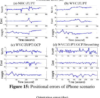
Figure 14 shows the filtering trajectories of iPhone 5S with different constraint algorithms. Figures 15 and 16 show the positional and orientation errors of iPhone scenario, respectively. Tables 8 and 9 show the numerical analyses of positional and orientation errors, respectively.
-20 -10 0 10 20 30 40 50 -10 0 10 20 30 40 N o rt h ( m ) East (m) Trajectory (0 = 22.9983819995, 0 = 120.2198180013 Filtering+NHC/ZUPT Filtering+WVC/ZUPT Filtering+WVC/ZUPT+GCP Smoothing+WVC/ZUPT+GCP MIDG smoothing
Figure 14: Trajectories of iPhone 5S with different constraints
Figure 15: Positional errors of iPhone scenario
Figure 16: Orientation errors of iPhone scenario
Table 8: Numerical analysis of positional errors for iPhone scenario
Table 9: Numerical analysis of orientation errors for iPhone scenario
The major errors of those trajectories are caused by human motion which produces unreasonable movement. The results show that the WVC significantly improved the accuracy of filtering solution in real-time, especially for maximum errors. Thus, the assumption of WVC is more appropriate for this kind of application. The improvement depends on the accuracy of step length and pedometer. The parameters of step length model didn’t adjust in post-processing in this study because of the purpose of real-time navigation. So they are default number from reference for two scenarios. However, it still provides the positional accuracy less than ten meter of RMSE for real-time filtering without the control point update.
Furthermore, the control point update fixes the trajectory at the correct location that reduces the remaining navigation error after the WVC. The control point further reduces the positional error to around 1 to 2 meter of RMSE. The WVC reduces the required amount of control points by maintaining the navigation accuracy within a longer time. The control point which are from the pre-survey and beacon in this study can be replaced by other positioning technologies with the available accuracy.
Smoothing with WVC/ZUPT and control point update in post-processing provide the positional accuracy around 50
-20 -10 0 10 20 30 40 50 60 70 -20 -10 0 10 20 30 40 50 60 N o rt h ( m ) East (m) Trajectory ( 0 = 22.9984019999, 0 = 120.2198490000 Filtering+NHC/ZUPT Filtering+WVC/ZUPT Filtering+WVC/ZUPT+GCP Smoothing+WVC/ZUPT+GCP MIDG smoothing
centimeter. However, the post-processing mode is inconvenient for real time case. In addition, the improvements of orientation accuracy in all scenarios are unobtrusive and slightly unstable but they still show the obvious trend of improvement when use more proposed algorithms.
The real-time smoothing
The scenarios of real-time smoothing are implemented with different window sizes. All trajectories are implemented with WVC/ZUPT and control point update. Figure 17 shows the real-time smoothing trajectories of Samsung S5 with different window sizes. Figures 18 and 19 show the positional and orientation errors of real-time smoothing for Samsung S5, respectively. Tables 10 and 11 show the numerical analyses of positional and orientation errors, respectively.
Figure 17: Trajectories of real-time smoothing of Samsung scenario
Figure 18: Positional errors of real-time smoothing of Samsung scenario
Figure 19: Orientation errors of real-time smoothing of Samsung scenario
Table 10: Positional error analysis with the real-time smoothing of Samsung scenario
-10 0 10 20 30 40 50 -10 -5 0 5 10 15 20 25 30 35 40 N o rt h ( m ) East (m) Trajectory (0 = 22.9983965173, 0 = 120.2197839573 OSM 5s+WVC/ZUPT+GCP OSM 10s+WVC/ZUPT+GCP OSM 20s+WVC/ZUPT+GCP MIDG smoothing
Table 11: Orientation error analysis with the real-time smoothing of Samsung scenario
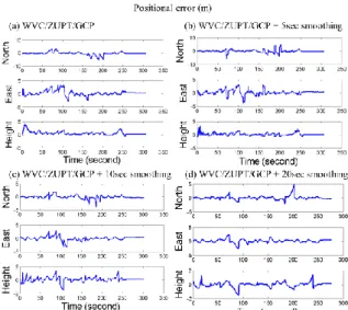
The scenarios of real-time smoothing for iPhone 5S are as same as those for Samsung S5. Figure 20 shows the real-time smoothing trajectories with different window sizes. Figures 21 and 22 show the positional and orientation errors of real-time smoothing for iPhone 5S respectively. Tables 12 and 13 show the positional and orientation errors analyses of real-time smoothing trajectories for iPhone 5S, respectively.
Figure 20: Trajectories of real-time smoothing of iPhone 5S
Figure 21: Positional errors of real-time smoothing of iPhone 5S
Figure 22: Orientation errors of real-time smoothing of iPhone 5S
Table 12: Positional error analysis with the real-time smoothing of iPhone 5S -10 0 10 20 30 40 -5 0 5 10 15 20 25 30 35 N o rt h ( m ) East (m) Trajectory ( 0 = 22.9984020291, 0 = 120.2198490113 OSM 5s+WVC/ZUPT+GCP OSM 10s+WVC/ZUPT+GCP OSM 20s+WVC/ZUPT+GCP MIDG smoothing
Table 13: Orientation error analysis with the real-time smoothing of iPhone 5S
The real-time smoothing for pedestrian indoor navigation with the WVC and control point update has better accuracy than the filtering solution. The improvement and stability increased when the window size of real-time smoothing become longer. In other words, the improvement becomes smaller and unstable when the window size becomes shorter such as 5s in this study. The highest improvement of real-time smoothing with 10 or 20s window provides the positional accuracy under the meter level. Figure 23 illustrates the relationship between window size and positional error.
Figure 23: Relationship between window size and
accuracy of real-time smoothing
The maximum errors of orientation are related to the correction of trajectory after control point update, as well as to the time synchronization between two sensors. However, the real-time smoothing still improve a little of the orientation errors for most results in RMSE.
In addition, the frequency of control point update also affects optimal window size because the basic concept of smoothing relates to the update measurement as well as the control point has higher effectiveness and reliability than
constraint algorithms. The optimal window size means the smallest window size which can obtain the required accuracy for pedestrian indoor navigation. The accuracy of 5s window is worse and the accuracy of 20s window is close to 10s window. In other words, the optimal window should longer than 5 second but no need to larger than 20 second in this case because the effectiveness of improvement is decreased with time. The amount and distance of control point in this study make the update almost implement in EKF at every 15s, which also implied the optimal window size shows in the results. Thus, the optimal window size may be shorter when the frequency of measurement update increased. The smoothing would be better to implement in near real-time mode when the control point is fewer.
CONCLUSIONS
The WVC and control point update improve the accuracy of filtering solution in real-time, especially for unreasonable movement which reflected in maximum errors. The performance of real-time smoothing is also verified and can thus provide the best performance in near real-time processing. The control point used in the proposed architecture can be replaced by other positioning technologies with the precondition of available accuracy. The suggested total solution would be the combination of WVC, control point update at crucial locations and real-time smoothing. This architecture has better accuracy and stability by reducing the error of WVC cause by the inaccurate step length model and pedometer. It also reduces the required amount of control points and the optimal size of real-time smoothing window. Therefore, the INS can provide the required accuracy at meter or sub-meter level with the proposed algorithms for pedestrian indoor navigation in real-time.
ACKNOWLEDGMENTS
The author would acknowledge the financial supports provided by the National Science Council of Taiwan NSC (102-2221-E-006 -137 -MY3) and all technical assistances from his supervisor, Dr. Kai-Wei Chiang.
REFERENCES
![Table 1: Summary of indoor navigation technologies [3]](https://thumb-ap.123doks.com/thumbv2/9libinfo/8996645.284495/2.893.66.417.188.410/table-summary-indoor-navigation-technologies.webp)