Preface, Contents
How to Design Control Programs
1
Structuring the User Program
2
Organization Blocks and Executing the
Program
3
Handling Interrupts
4
Memory Areas of S7 CPUs
5
Addressing Peripheral I/Os
6
Data Exchange Between Programmable
Modules
7
Setting System Parameters
8
Operating Modes and Mode Changes
9
Multicomputing
10
Diagnostics and Troubleshooting
11
Sample Program for an Industrial
Blending Process
A
Sample Program for Communication
SFBs for Configured Connections
B
Data and Parameter Types
C
References
D
Glossary, Index
C79000-G7076-C506-01
System Software
for S7-300 and S7-400 Program Design
Programming Manual
SIMATIC
长沙工控帮教育科技有限公司整理
!
Dangerindicates that death, severe personal injury or substantial property damage will result if proper precautions are not taken.!
Warningindicates that death, severe personal injury or substantial property damage can result if proper precautions are not taken.!
Cautionindicates that minor personal injury or property damage can result if proper precautions are not taken.Note
draws your attention to particularly important information on the product, handling the product, or to a particular part of the documentation.
The device/system may only be set up and operated in conjunction with this manual.
Only qualified personnel should be allowed to install and work on this equipment. Qualified persons are defined as persons who are authorized to commission, to ground, and to tag circuits, equipment, and sys- tems in accordance with established safety practices and standards.
Note the following:
!
WarningThis device and its components may only be used for the applications described in the catalog or the technical description, and only in connection with devices or components from other manufacturers which have been approved or recommended by Siemens.This product can only function correctly and safely if it is transported, stored, set up, and installed correctly, and operated and maintained as recommended.
SIMATICR and SINECR are registered trademarks of SIEMENS AG.
Third parties using for their own purposes any other names in this document which refer to trademarks might infringe upon the rights of the trademark owners.
We have checked the contents of this manual for agreement with the hardware and software described. Since deviations cannot be precluded entirely, we cannot guarantee full agreement. However, the data in this manual are reviewed regularly and any necessary corrections included in subsequent editions. Suggestions for improvement are welcomed.
Technical data subject to change.
E Siemens AG 1996 Disclaimer of Liability Copyright E Siemens AG 1996 All rights reserved
The reproduction, transmission or use of this document or its contents is not permitted without express written authority. Offenders will be liable for damages. All rights, including rights created by patent grant or registration of a utility model or design, are reserved.
Siemens AG Automation Group
Industrial Automation Systems Postfach 4848, D-90327 Nürnberg
Qualified Personnel
Correct Usage
Trademarks
长沙工控帮教育科技有限公司整理
Preface
This manual describes the various ways in which you can program your S7-300/S7-400 programmable logic controller (PLC). The manual focuses primarily on the tasks you need to perform when designing a project “on paper”.
The manual has the following aims:
S To familiarize you with the operating systems of the S7-300 and S7-400 CPUs
S To support you when designing your user program
S To inform you about the opportunities for communication and diagnostics with the S7-300 and S7-400 CPUs
For information about the different programming languages, refer to the corresponding manuals (refer also to the overview of the STEP 7 documentation).
This manual is intended for users involved in controlling processes and who are responsible for designing programs for programmable controllers. The manual describes the tasks that can be performed without using the STEP 7 software, such as determining the program sequence for a design project.
This manual applies to the following CPUs of the S7-300 and S7-400:
CPU Order Number Version (or higher)
CPU 312 IFM 6ES7312-5AC00-0AB0 03
CPU 313 6ES7313-1AD00-0AB0 01
CPU 314 6ES7314-1AE00-0AB0 04
CPU 314 IFM 6ES7312-5AE00-0AB0 01
CPU 315 6ES7314-1AF00-0AB0 03
CPU 315-2 DP 6ES7314-2AF00-0AB0 03
CPU 412-1 6ES7412-1XF00-0AB0 01
CPU 413-1 6ES7413-1XG00-0AB0 01
CPU 413-2 6ES7413-2XG00-0AB0 01
CPU 414-1 6ES7414-1XG00-0AB0 01
Purpose
Audience
Scope of the
Manual 长沙工控帮教育科技有限公司整理
CPU Order Number Version (or higher)
CPU 414-2 with 384K 6ES7414-2XJ00-0AB0 01
CPU 416-1 6ES7416-1XJ01-0AB0 01
CPU 416-2 with 0.8M 6ES7416-2XK00-0AB0 01
CPU 416-2 with 1.6M 6ES7416-2XL00-0AB0 01
The CPU functions described in this manual can be used from Version 3.1 or higher of the STEP 7 standard software.
There is a wide range of general and specific user documentation available to support you when configuring and programming an S7 programmable logic controller. The following tables and the figure below will help you find the user documentation you require.
Overview of the STEP 7
Documentation
长沙工控帮教育科技有限公司整理
STL LAD FBD SCL
CFC for S7
Reference Manual Program-
ming Manual
User Manual
GRAPH HiGraph
/234/
/231/
/232/ /233/ /236/ /250/
/254/
/251/ /252/
/xxx/: Number in the literature list /235/
System Software for S7-300/S7-400 Program Design
Standard Software for S7 and M7 STEP 7
Primer
/30/
S7-300 Programmable Controller Quick Start
System Software for S7-300/400 System and Standard Functions User
Manual /230/
Standard Software for S7-300/S7-400 Converting S5 Programs
Language Packages Online Help
This symbol indicates the order in which you should read the manuals, particularly if you are a first-time user of S7.
This documentation introduces the methodology.
Reference works which are only required selectively.
The documentation is supported by an online help.
Symbol Meaning
Manuals on S7-300/S7-400 Hardware Manual
长沙工控帮教育科技有限公司整理
Title Subject S7-300 Programmable
Controller
Quick Start, Primer
The primer provides you with a very simple introduction to the methods of configuring and programming an S7-300/400. It is particularly suitable for first-time users of an S7 programmable controller.
S7-300 and S7-400 Program Design Programming Manual
The “S7-300/400 Program Design” programming manual provides you with the basic information you require about the structure of the operating system and a user program for an S7 CPU. First-time users of an S7-300/400 should use this manual to get a basic overview of programming methods on which to base the design of a user program.
S7-300 and S7-400 System and Standard Functions
Reference Manual
The S7 CPUs have system functions and organization blocks integrated in the operating system that can be used when programming. The manual provides you with an overview of the system functions, organization blocks and loadable standard functions available with an S7 programmable controller and contains detailed interface
descriptions explaining how to use the functions and blocks in your user program.
STEP 7 User Manual
The “STEP 7” User Manual explains the basic use and functions of the STEP 7 automation software. Whether you are a first-time user of STEP 7 or an experienced STEP 5 user, the manual will provide you with an overview of the procedures for configuring, programming and getting started with an S7-300/400 programmable controller. When working with the software, you can call up the online help which supports you with information about specific details of the program.
Converting S5 Programs Manual
You require the “Converting S5 Programs” User Manual if you want to convert existing S5 programs and to run them on S7 CPUs. The manual explains how to use the converter. The online help system provides more detailed information about using the specific converter functions. The online help system also includes an interface description of the available converted S7 functions.
STL, LAD, FBD, SCL1 Manuals
The manuals for the language packages STL, LAD, FBD, and SCL contain both instructions for the user and a description of the language. To program an S7-300/400, you only require one of the languages, but you can, if required, mix the languages within a project. When using one of the languages for the first time, it is advisable to familiarize yourself with the methods of creating a program as explained in the manual.
When working with the software, you can use the online help system which provides you with detailed information about using the editors and compilers.
GRAPH1 , HiGraph1, CFC1
Manuals
The GRAPH, HiGraph, and CFC languages provide you with optional methods for implementing sequential control systems, status control systems, or graphical interconnection of blocks. The manuals contain both the user instructions and the description of the language. When using one of these languages for the first time, it is advisable to familiarize yourself with the methods of creating a program based on the
“S7-300 and S7-400 Program Design” manual. When working with the software, you can also use the online help system (with the exception of HiGraph) that provides you with detailed information about using the editors and compilers.
1 Optional package for system software for S7-300/S7-400
The various S7-300 and S7-400 CPUs, the S7-300 and S7-400 modules, and the instructions of the CPU are described in the following manuals:
S For the S7-300 programmable logic controller, refer to the manuals:
Hardware and Installation (CPU Data, Module Data) and the Instruction List.
S For the S7-400 programmable logic controller, refer to the manuals:
Hardware and Installation (CPU Data, Module Data) and the Instruction List.
Other Manuals
长沙工控帮教育科技有限公司整理
Since this manual provides you with a basic overview of the operating system of the S7-300/400, we recommend that you first have a look at the general contents of the chapters and then select the topics that you will require when designing your program for more intensive reading.
S Chapter 1 describes the basic tasks involved in planning an automation project.
S Chapter 2 shows you how to select the block structure for your S7 program.
S Chapters 3 and 4 describe the role of the organization blocks when the CPU executes your program.
S Chapters 5 and 6 describe the memory areas of the CPU and explain how the I/Os are addressed.
S Chapters 7 and 8 describe how you can exchange data between S7-CPUs and how you can adapt certain properties of a programmable logic controller by setting system parameters.
S Chapter 9 provides an overview of the operating modes and the various types of startup on the S7-CPUs. The chapter also explains how the operating system supports you when debugging your user program.
S Chapter 10 describes the multicomputing mode and the points to note when programming for this mode.
S Chapter 11 describes system diagnostics for S7-CPUs and explains how to eliminate errors and problems.
S Appendix A and Appendix B contain sample programs for an industrial blending process and for the data exchange using communication function blocks.
S Appendix C is a reference section listing data and parameter types.
S Appendix D contains the list of Literature referred to in the manual.
S The Glossary explains important terms used in the manual. The Index helps you to locate sections of text and topics quickly.
References to other manuals and documentation are indicated by numbers in slashes /.../. These numbers refer to the titles of manuals listed in
Appendix KEIN MERKER.
If you have any questions regarding the software described in this manual and cannot find an answer here or in the online help, please contact the Siemens representative in your area. You will find a list of addresses in the Appendix of /70/ or /100/, or in catalogs, and in Compuserve (go
autforum). You can also speak to our Hotline under the following phone or fax number:
Tel. (+49) (911) 895-7000 (Fax 7001) How to Use this
Manual
Conventions
Additional Assistance
长沙工控帮教育科技有限公司整理
If you have any questions or comments on this manual, please fill out the remarks form at the end of the manual and return it to the address shown on the form. We would be grateful if you could also take the time to answer the questions giving your personal opinion of the manual.
Siemens also offers a number of training courses to introduce you to the SIMATIC S7 automation system. Please contact your regional training center or the central training center in Nuremberg, Germany for details:
D-90327 Nuremberg, Tel. (+49) (911) 895-3154.
长沙工控帮教育科技有限公司整理
Contents
1 How to Design Control Programs . . . 1-1 1.1 Planning the Automation Project . . . 1-2 1.2 Dividing the Process into Individual Tasks . . . 1-3 1.3 Describing the Individual Tasks and Areas. . . 1-5 1.4 Establishing the Safety Requirements . . . 1-9 1.5 Describing the Required Operator Displays and Controls . . . 1-10 1.6 Creating a Configuration Diagram . . . 1-11 2 Structuring the User Program . . . 2-1 2.1 The Programs in a CPU. . . 2-2 2.2 Elements of the User Program . . . 2-3 2.3 Call Hierarchy of the Blocks . . . 2-4 2.4 Variables of a Block . . . 2-5 2.5 Range of Instructions of the S7 CPUs. . . 2-7 2.6 Organization Blocks (OB) and Program Structure . . . 2-9 2.7 System Function Blocks (SFB) and System Functions (SFC) . . . 2-10 2.8 Functions (FC). . . 2-11 2.9 Function Blocks (FB) . . . 2-12 2.10 Instance Data Blocks . . . 2-15 2.11 Shared Data Blocks (DB) . . . 2-17 2.12 Saving the Data of an Interrupted Block . . . 2-18 2.13 Avoiding Errors when Calling Blocks. . . 2-20
长沙工控帮教育科技有限公司整理
3 Organization Blocks and Executing the Program . . . 3-1 3.1 Types of Organization Block . . . 3-2 3.2 Organization Blocks for the Startup Program . . . 3-4 3.3 Organization Block for Cyclic Program Execution. . . 3-5 3.4 Organization Block for Background Program Execution . . . 3-7 3.5 Organization Blocks for Interrupt-Driven Program Execution . . . 3-8 3.6 Organization Blocks for Handling Errors. . . 3-10 3.7 Interrupting Program Execution . . . 3-12 3.8 Managing Local Data (L Stack) . . . 3-13 4 Handling Interrupts . . . 4-1 4.1 Using Interrupt OBs . . . 4-2 4.2 Time-of-Day Interrupts (OB10 to OB17) . . . 4-3 4.3 Time-Delay Interrupts (OB20 to OB23). . . 4-5 4.4 Cyclic Interrupts (OB30 to OB38). . . 4-6 4.5 Hardware Interrupts (OB40 to OB47) . . . 4-8 5 Memory Areas of S7 CPUs . . . 5-1 5.1 Memory Areas of the CPU . . . 5-2 5.2 Absolute and Symbolic Addressing . . . 5-5 5.3 Storing Programs on the CPU . . . 5-6 5.4 Retentive Memory Areas on S7-300 CPUs . . . 5-8 5.5 Retentive Memory Areas on S7-400 CPUs . . . 5-10 5.6 Process Image Input/Output Tables. . . 5-11 5.7 Local Data Stack. . . 5-13 6 Addressing Peripheral I/Os. . . 6-1 6.1 Access to Process Data. . . 6-2 6.2 Access to the Peripheral Data Area. . . 6-4 6.3 Special Features of Distributed Peripheral I/Os (DP) . . . 6-6 7 Data Exchange Between Programmable Modules . . . 7-1 7.1 Types of Communication. . . 7-2 7.2 Data Exchange with SFBs for Configured Connections. . . 7-3 7.3 Configuring a Communication Connection Between Partners . . . 7-5 7.4 Working with Communication SFBs for Configured Connections . . . 7-7 7.5 Data Exchange with Communication SFCs for
Non-Configured Connections . . . 7-8
长沙工控帮教育科技有限公司整理
8 Setting System Parameters . . . 8-1 8.1 Changing the Behavior and Properties of Modules . . . 8-2 8.2 Using the Clock Functions. . . 8-4 8.3 Specifying the Startup Behavior. . . 8-5 8.4 Settings for the Cycle . . . 8-6 8.5 Specifying the MPI Parameters . . . 8-9 8.6 Specifying Retentive Memory Areas . . . 8-10 8.7 Using Clock Memory and Timers . . . 8-11 8.8 Changing the Priority Classes and Amount of Local Data. . . 8-12 9 Operating Modes and Mode Changes . . . 9-1 9.1 Operating Modes and Mode Changes . . . 9-2 9.2 STOP Mode . . . 9-5 9.3 STARTUP Mode . . . 9-6 9.4 RUN Mode . . . 9-12 9.5 HOLD Mode. . . 9-13 9.6 Testing the User Program . . . 9-14 10 Multicomputing . . . 10-1 10.1 Overview . . . 10-2 10.2 Configuring Modules . . . 10-4 10.3 Programming the CPUs. . . 10-6 10.4 Synchronizing the CPUs . . . 10-8 10.5 Dealing with Errors . . . 10-10 11 Diagnostics and Troubleshooting. . . 11-1 11.1 Diagnostic Information . . . 11-2 11.2 System Status List SZL . . . 11-4 11.3 Diagnostic Buffer. . . 11-7 11.4 Sending Your Own Diagnostic Messages. . . 11-8 11.5 Evaluating the Output Parameter RET_VAL . . . 11-9 11.6 Error OBs as a Reaction to Detected Errors . . . 11-10 11.7 Using “Replacement Values” When an Error is Detected . . . 11-14 11.8 Time Error OB (OB80) . . . 11-17 11.9 Power Supply Error OB (OB81) . . . 11-18 11.10 Diagnostic Interrupt OB (OB82) . . . 11-19 11.11 Insert/Remove Module Interrupt OB (OB83) . . . 11-20
长沙工控帮教育科技有限公司整理
11.13 Priority Class Error OB (OB85). . . 11-22 11.14 Rack Failure OB (OB86) . . . 11-23 11.15 Communication Error OB (OB87) . . . 11-24 11.16 Programming Error OB (OB121) . . . 11-25 11.17 I/O Access Error OB (OB122). . . 11-26 A Sample Program for an Industrial Blending Process . . . A-1 A.1 Example of an Industrial Blending Process . . . A-2 A.2 Defining Logic Blocks. . . A-4 A.3 Assigning Symbolic Names. . . A-5 A.4 Creating the FB for the Motor . . . A-7 A.5 Creating the FC for the Valves . . . A-11 A.6 Creating OB1. . . A-13 B Sample Program for Communication SFBs for Configured Connections. . . B-1 B.1 Overview . . . B-2 B.2 Sample Program on the Sending CPU . . . B-3 B.3 Sample Program on the Receiving CPU. . . B-6 B.4 Using the Sample Program. . . B-8 B.5 Call Hierarchy of the Blocks in the Sample Program . . . B-9 C Data and Parameter Types . . . C-1 C.1 Data Types. . . C-2 C.2 Using Complex Data Types. . . C-6 C.3 Using Arrays to Access Data . . . C-7 C.4 Using Structures to Access Data . . . C-10 C.5 Using User-Defined Data Types to Access Data. . . C-12 C.6 Using the ANY Parameter Type . . . C-15 C.7 Assigning Data Types to Local Data of Logic Blocks . . . C-17 C.8 Restrictions When Transferring Parameters . . . C-19 D References. . . D-1 Glossary . . . Glossary-1 Index. . . Index-1
长沙工控帮教育科技有限公司整理
How to Design Control Programs
This chapter outlines the basic tasks involved in planning an automation project and designing a user program for a programmable controller (PLC).
Based on an example of automating an industrial blending process, you are guided step by step through the procedure.
The example of a program for an industrial blending process is described in Appendix A.
Section Description Page
1.1 Planning the Automation Project 1-2
1.2 Dividing the Process into Individual Tasks 1-3
1.3 Describing the Individual Tasks and Areas 1-5
1.4 Establishing the Safety Requirements 1-9
1.5 Describing the Required Operator Displays and Controls 1-10
1.6 Creating a Configuration Diagram 1-11
What Does This Chapter Describe?
Where to Find More Information
Chapter Overview
1
长沙工控帮教育科技有限公司整理
1.1 Planning the Automation Project
There are many ways of planning an automation project. This section describes a basic procedure that you can use for any project.
Figure 1-1 outlines the basic steps.
Divide the process into tasks
Describe the individual tasks and areas
Define the safety requirements
Describe the required operator displays and controls
Create configuration diagrams of your programmable controller
Figure 1-1 Basic Steps When Planning an Automation Project The individual steps are described in detail in Sections 1.2 to 1.6.
Overview
长沙工控帮教育科技有限公司整理
1.2 Dividing the Process into Individual Tasks
A process consists of individual tasks. By identifying groups of related tasks within a process and then breaking these groups down into smaller tasks, even the most complex process can be defined.
The following example of an industrial blending system can be used to illustrate how to organize a process into functional areas and individual tasks.
(see Figure 1-2).
M
M
Drain solenoid valve Switch for tank level measurement Agitator motor
Ingredient A
Ingredient B Inlet valve
Feed valve Feed
pump
Inlet valve
Feed valve Feed
pump
Flow sensor M
M M
M
Figure 1-2 Example of an Industrial Blending Process
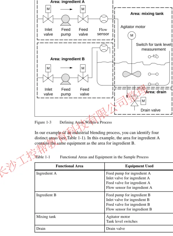
After defining the process to be controlled, divide the project into related groups or areas (see Figure 1-3). As each group is divided into smaller tasks, the tasks required for controlling that part of the process become less complicated.
Overview
Identifying Areas and Tasks within the Process
长沙工控帮教育科技有限公司整理
M
M
Drain valve Switch for tank level
measurement Agitator motor
Inlet valve
Feed valve Feed
pump
Inlet valve
Feed valve Feed
pump
Flow sensor
Area: ingredient B Area: ingredient A
Area: mixing tank M
M M
M
Area: drain
Figure 1-3 Defining Areas Within a Process
In our example of an industrial blending process, you can identify four distinct areas (see Table 1-1). In this example, the area for ingredient A contains the same equipment as the area for ingredient B.
Table 1-1 Functional Areas and Equipment in the Sample Process
Functional Area Equipment Used
Ingredient A Feed pump for ingredient A
Inlet valve for ingredient A Feed valve for ingredient A Flow sensor for ingredient A
Ingredient B Feed pump for ingredient B
Inlet valve for ingredient B Feed valve for ingredient B Flow sensor for ingredient B
Mixing tank Agitator motor
Tank level switches
Drain Drain valve
长沙工控帮教育科技有限公司整理
1.3 Describing the Individual Tasks and Areas
As you describe each area and task within your process, you define not only the operation of each area, but also the various elements that control the area.
These include:
S Electrical, mechanical, and logical inputs and outputs for each task S Interlocks and dependencies between the individual tasks
The sample industrial blending process uses pumps, motors and valves.
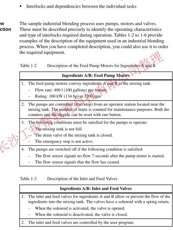
These must be described precisely to identify the operating characteristics and type of interlocks required during operation. Tables 1-2 to 1-6 provide examples of the description of the equipment used in an industrial blending process. When you have completed description, you could also use it to order the required equipment.
Table 1-2 Description of the Feed Pump Motors for Ingredients A and B Ingredients A/B: Feed Pump Motors
1. The feed pump motors convey ingredients A and B to the mixing tank.
– Flow rate: 400 l (100 gallons) per minute – Rating: 100 kW (134 hp) at 1200 rpm
2. The pumps are controlled (start/stop) from an operator station located near the mixing tank. The number of starts is counted for maintenance purposes. Both the counters and the display can be reset with one button.
3. The following conditions must be satisfied for the pumps to operate:
– The mixing tank is not full.
– The drain valve of the mixing tank is closed.
– The emergency stop is not active.
4. The pumps are switched off if the following condition is satisfied:
– The flow sensor signals no flow 7 seconds after the pump motor is started.
– The flow sensor signals that the flow has ceased.
Table 1-3 Description of the Inlet and Feed Valves Ingredients A/B: Inlet and Feed Valves
1. The inlet and feed valves for ingredients A and B allow or prevent the flow of the ingredients into the mixing tank. The valves have a solenoid with a spring return.
– When the solenoid is activated, the valve is opened.
– When the solenoid is deactivated, the valve is closed.
2. The inlet and feed valves are controlled by the user program.
Overview
Describing How the Areas Function
长沙工控帮教育科技有限公司整理
Table 1-3 Description of the Inlet and Feed Valves, continued Ingredients A/B: Inlet and Feed Valves
3. For the valves to be activated, the following condition must be satisfied:
– The feed pump motor has been running for at least 1 second.
4. The valves are deactivated if the following condition is satisfied:
– The flow sensor signals no flow.
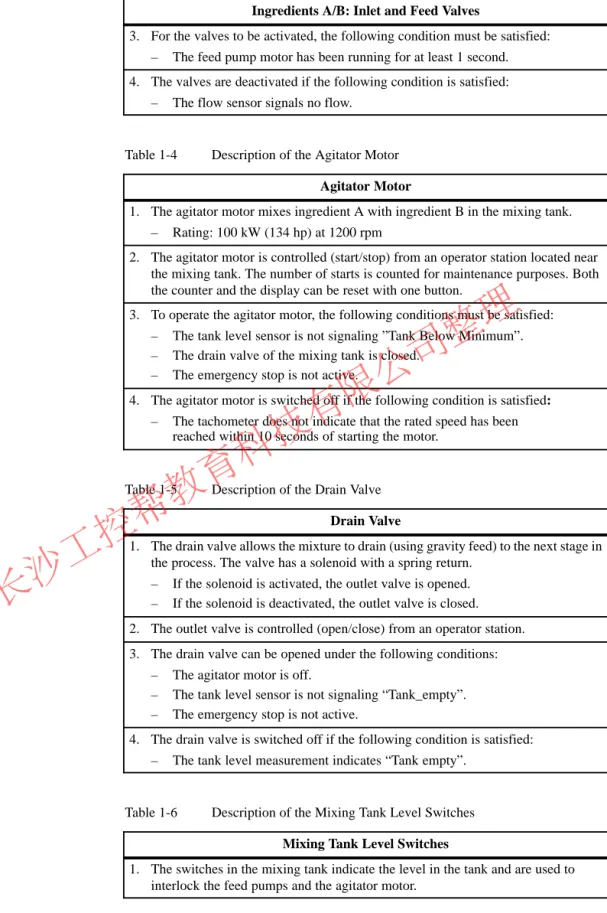
Table 1-4 Description of the Agitator Motor Agitator Motor
1. The agitator motor mixes ingredient A with ingredient B in the mixing tank.
– Rating: 100 kW (134 hp) at 1200 rpm
2. The agitator motor is controlled (start/stop) from an operator station located near the mixing tank. The number of starts is counted for maintenance purposes. Both the counter and the display can be reset with one button.
3. To operate the agitator motor, the following conditions must be satisfied:
– The tank level sensor is not signaling ”Tank Below Minimum”.
– The drain valve of the mixing tank is closed.
– The emergency stop is not active.
4. The agitator motor is switched off if the following condition is satisfied:
– The tachometer does not indicate that the rated speed has been reached within 10 seconds of starting the motor.
Table 1-5 Description of the Drain Valve Drain Valve
1. The drain valve allows the mixture to drain (using gravity feed) to the next stage in the process. The valve has a solenoid with a spring return.
– If the solenoid is activated, the outlet valve is opened.
– If the solenoid is deactivated, the outlet valve is closed.
2. The outlet valve is controlled (open/close) from an operator station.
3. The drain valve can be opened under the following conditions:
– The agitator motor is off.
– The tank level sensor is not signaling “Tank_empty”.
– The emergency stop is not active.
4. The drain valve is switched off if the following condition is satisfied:
– The tank level measurement indicates “Tank empty”.
Table 1-6 Description of the Mixing Tank Level Switches Mixing Tank Level Switches
1. The switches in the mixing tank indicate the level in the tank and are used to interlock the feed pumps and the agitator motor.
长沙工控帮教育科技有限公司整理
After writing a physical description of each device to be controlled, draw diagrams of the inputs and outputs for each device or task area. (see Figure 1-4). These diagrams correspond to the logic blocks to be programmed.
Device Input 1
Input n In/out 1
In/out n
Output n Output 1
Figure 1-4 Input/Output Diagram
In the example of the industrial blending process, two feed pumps and an agitator are used. The required motors are controlled by a “motor block” that is the same for all three devices. This block requires six inputs: two to start or stop the motor, one to reset the maintenance display, one for the motor response signal (motor running/not running), one for the time during which the response signal must be received, and one for the number of the timer used to measure the time.
The logic block also requires four outputs: two to indicate the operating state of the motor, one to indicate faults, and one to indicate that the motor is due for maintenance.
An in/out is also necessary to activate the motor. This is also processed or modified in the “motor block” program.
Motor Start
Response Reset_Maint Timer_No
Fault
Maint Stop_Dsp Start_Dsp Stop
Response_Time
Motor
Figure 1-5 I/O Diagram of the Agitator Motor “Motor Block”
Creating Input/Output Diagrams
Creating an I/O Diagram for the Motor
长沙工控帮教育科技有限公司整理
Each valve is controlled by a “valve block” that is the same for all the valves used. The logic block has two inputs: one to open and one to close the valve.
It also has two outputs: one to indicate that the valve is open and the other to indicated that it is closed.
The block has an in/out to activate the valve. This is also processed or modified in the “valve block” program.
Valve Open
Valve
Dsp_Closed Close
Dsp_Open
Figure 1-6 I/O Diagram of the Valves Creating an I/O
Diagram for the Valves
长沙工控帮教育科技有限公司整理
1.4 Establishing the Safety Requirements
Decide which additional elements are needed to ensure the safety of the process, based on legal requirements and corporate policy. In your
description, you should also include any influences that the safety elements have on your process areas.
Find out which devices require hardwired circuits to meet safety
requirements. By definition, these safety circuits operate independently of the programmable controller (although the safety circuit generally provides an I/O interface to allow coordination with the user program). Normally, you configure a matrix to connect every actuator with its own emergency off range. This matrix is the basis for the circuit diagrams of the safety circuits.
To design safety mechanisms, follow the steps outline below:
S Determine the logical and mechanical/electrical interlocks between the individual automation tasks.
S Design circuits to allow the devices belonging to the process to be operated manually in an emergency.
S Establish any further safety requirements for safe operation of the process.
The sample industrial blending process uses the following logic for its safety circuit:
S One Emergency Stop push button shuts down the following devices independent of the programmable controller (PLC):
– Ingredient A feed pump – Ingredient B feed pump – Agitator motor
– Valves
S The Emergency Stop push button is located on the operator station.
S An input to the controller indicates the state of the Emergency Stop push button.
Overview
Defining Safety Requirements
Creating a Safety Circuit
长沙工控帮教育科技有限公司整理
1.5 Describing the Required Operator Displays and Controls
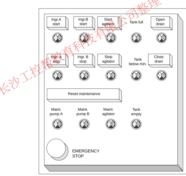
Every process needs an operator interface that allows human intervention in the process. Part of the design specification includes the design of the operator station.
In the industrial blending process described in our example, each device can be started or stopped by a push button located on the operator station. This operator station includes indicators to show the status of the operation (see Figure 1-7). The console also includes display lamps for devices that require maintenance after a certain number of starts and the emergency stop switch with which the process can be stopped immediately. The console also has a reset button for the maintenance display of the three motors. Using this, you can turn off the maintenance display lamps for the motors due for
maintenance and reset the corresponding counters to 0.
EMERGENCY STOP Ingr. A
stop Ingr.A
start
Ingr. B stop
Start agitator
Stop agitator
Tank full
Tank below min.
Tank empty
Open drain
Close drain
Maint.
pump A
Maint.
pump B
Maint.
agitator Ingr.B
start
Reset maintenance
Figure 1-7 Example of an Operator Station Console Overview
Defining an Operator Station
长沙工控帮教育科技有限公司整理
1.6 Creating a Configuration Diagram
After you have documented the design requirements, you must then decide on the type of control equipment required for the project.
By deciding which modules you want to use, you also specify the structure of the programmable controller. Create a configuration diagram specifying the following aspects:
S Type of CPU
S Number and type of I/O modules
S Configuration of the physical inputs and outputs
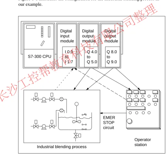
Figure 1-8 illustrates the configuration for the industrial blending process in our example.
Digital input module
Digital output module
Digital output module
Industrial blending process
Operator station S7-300 CPU
I 0.0 to I 1.7
Q 4.0 to Q 5.0
Q 8.0 to Q 9.0
EMER STOP circuit
Figure 1-8 Example of an S7 Configuration Diagram Overview
Determining the PLC Configuration
长沙工控帮教育科技有限公司整理
长沙工控帮教育科技有限公司整理
Structuring the User Program
This chapter will help you when you are deciding on the block structure of your S7 program. It describes the following:
S The programs of a CPU: operating system and user program S The structure of user programs
S The elements of a user program
The reference manual /235/ contains a detailed description of the individual organization blocks and system functions.
The Instruction Lists /72/ and /102/ contain an overview of the range of instructions of the S7-300 and S7-400 CPUs.
Section Description Page
2.1 The Programs in a CPU 2-2
2.2 Elements of the User Program 2-3
2.3 Call Hierarchy of the Blocks 2-4
2.4 Variables of a Block 2-5
2.5 Range of Instructions of the S7 CPUs 2-7
2.6 Organization Blocks (OB) and Program Structure 2-9 2.7 System Function Blocks (SFB) and System Functions
(SFC)
2-10
2.8 Functions (FC) 2-11
2.9 Function Blocks (FB) 2-12
2.10 Instance Data Blocks 2-15
2.11 Shared Data Blocks (DB) 2-17
2.12 Saving the Data of an Interrupted Block 2-18
2.13 Avoiding Errors when Calling Blocks 2-20
What Does This Chapter Describe?
Where to Find More Information
Chapter Overview
2
长沙工控帮教育科技有限公司整理
2.1 The Programs in a CPU
Two different types of program run on a CPU:
S The operating system S The user program.
Every CPU has an operating system that organizes all the functions and sequences of the CPU that are not associated with a specific control task. The tasks of the operating system include the following:
S Handling a complete restart and restart
S Updating the process image table of the inputs and outputting the process image table of the outputs
S Calling the user program
S Detecting interrupts and calling the interrupt OBs S Detecting and dealing with errors
S Managing the memory areas
S Communicating with programming devices and other communications partners
If you change operating system parameters (the operating system default settings), you can influence the activities of the CPU in certain areas (see Chapter 8).
You yourself must create the user program and load it on the CPU. This contains all the functions required to process your specific automation task.
The tasks of the user program include the following:
S Specifying the conditions for a complete restart and warm restart on the CPU (for example initializing signals with a particular value)
S Processing process data (for example logically combining binary signals, reading in and evaluating analog signals, specifying binary signals for output, outputting analog values)
S Specifying the reaction to interrupts
S Handling disturbances in the normal running of the program Introduction
Operating System
User Program
长沙工控帮教育科技有限公司整理
2.2 Elements of the User Program
The STEP 7 programming software allows you to structure your user program, in other words to break down the program into individual, self-contained program sections. This has the following advantages:
S Extensive programs are easier to understand.
S Individual program sections can be standardized.
S Program organization is simplified.
S It is easier to make modifications to the program.
S Debugging is simplified since you can test separate sections.
S Commissioning your system is made much easier.
The example of an industrial blending process in Chapter 1 illustrated the advantages of breaking down an automation process into individual tasks.
The program sections of a structured user program correspond to these individual tasks and are known as the blocks of a program.
An S7 user program consists of blocks, instructions and addresses. Table 2-1 provides you with an overview.
Table 2-1 Elements of a User Program
Element Function Refer to
Organization Blocks (OBs) OBs determine the structure of the user program.
S They form the interface between the operating system and the user program.
S They control the startup of the programmable logic controller, the cyclic and interrupt-driven program execution and are responsible for handling errors.
Section 2.6, Chapters 3, 4, 11
System function blocks (SFBs) and system functions (SFCs)
These are standard, preprogrammed blocks that you do not need to program yourself. SFBs and SFCs are integrated in the S7 CPU. They can be called by the user program. Since these blocks are part of the operating system they do not need to be loaded as part of the program like other blocks.
Section 2.7, Chapters 7, 8
Functions (FCs) and function blocks (FBs)
These are logic blocks that you yourself must program. FBs are blocks with an associated memory area that is used to supply parameters. FCs are blocks that do not have an associated memory area for supplying parameters.
Sections 2.8, 2.9
Data blocks These are data areas containing user data. There are two types of data block:
S Instance data blocks that are assigned to an FB
S Shared data blocks that can be accessed by all logic blocks
Sections 2.10, 2.11
Instructions of the S7 CPU The CPUs provide you with instructions with which you can create blocks in various programming languages.
Section 2.5 Overview
长沙工控帮教育科技有限公司整理
2.3 Call Hierarchy of the Blocks
Before the blocks in a user program can be processed, they must be called.
These calls are special STEP 7 instructions known as block calls. You can only program block calls within logic blocks (OBs, FBs, FCs, SFBs and SFCs). They can be compared with jumps to a subroutine. Each jump means that you change to a different block. The return address in the calling block is saved temporarily by the system.
The order and nesting of the block calls is known as the call hierarchy. The number of blocks that can be nested, (the nesting depth) depends on the particular CPU.
OB FB FC
FB FB SFC
Operating system FC DB
Figure 2-1 Example of the Call Hierarchy of a User Program
Figure 2-2 shows the sequence of a block call within a user program. The program calls the second block whose instructions are then executed completely.
Once the second or called block has been executed, execution of the interrupted block that made the call is resumed at the operation following the block call.
Instruction that calls another block
Block end Calling block
(OB, FB, FC)
Called block
(FB, FC, SFB or SFC) Program
execution
Program execution
Figure 2-2 Calling a Block
Before you program a block, you must specify which data will be used by your program, in other words, you must declare the variables of the block.
Introduction
Block Calls
长沙工控帮教育科技有限公司整理
2.4 Variables of a Block
Apart from the instructions of the user program, blocks also contain block variables that you declare using STEP 7 when you program your own blocks.
In the variable declaration, you can specify variables that the block will use when it is being executed. Variables are as follows:
S Parameters that are transferred between logic blocks.
S Static variables that are saved in an instance data block and are retained after the function block to which they belong has been executed.
S Temporary variables that are only available while the block is being executed and are then free to be overwritten when the block is completed.
The operating system assigns a separate memory area for temporary data (see also Section 3.8 Local Data Stack).
Since you can transfer parameters to blocks, you can create general, re-usable blocks whose programs can be used by other blocks in your program. There are two types of parameter as follows:
S Formal parameters that identify the parameters. These are specified in the variable declaration.
S Actual parameters that replace the formal parameters when the block is called.
For every formal parameter, you must specify a declaration type and a data type.
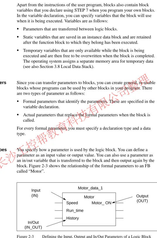
You specify how a parameter is used by the logic block. You can define a parameter as an input value or output value. You can also use a parameter as an in/out variable that is transferred to the block and then output again by the block. Figure 2-3 shows the relationship of the formal parameters to an FB called “Motor”.
Motor_data_1
Speed Run_time History
Motor_ ON
In/Out (IN_OUT)
Output (OUT) Motor
Input (IN)
Figure 2-3 Defining the Input, Output and In/Out Parameters of a Logic Block Introduction
Block Parameters
Declaration Types
长沙工控帮教育科技有限公司整理
Table 2-2 describes the declaration types.
Table 2-2 Declaration Types for Parameters and Local Variables Parameter/
Variable
Description Permitted
in IN Input parameter provided by the calling logic block. FB, FC OUT Output parameter provided by the calling block. FB, FC IN_OUT Parameter whose value is supplied by the calling block,
modified by the called block and returned to the calling block.
FB, FC
STAT Static variable that is saved in an instance DB. FB TEMP Temporary variable that is saved temporarily in the local
data stack. Once the logic block has been executed com- pletely, the value of the variable is no longer available.
FB, FC, OB
With FBs, the data that was declared as IN, OUT, IN_OUT, and all static variables (STAT) are saved in the instance DB. Temporary variables of the type TEMP are not saved.
FCs cannot have any static variables. The input, output and in/out parameters are saved as pointers to the actual parameters made available by the calling block.
All the data used in a user program must be identified by a data type. When you define the data type for parameters and static or temporary variables, you also specify the length and structure of the variables. The actual parameter supplied when the block is called must have the same data type as the formal parameter. Variables can have the following data types:
S Elementary data types that are provided by STEP 7
S Complex data types that you can create by combining elementary data types
S User-defined data types
S Parameter types that define special parameters that are transferred to FBs or FCs
Data types and parameter types are described in detail in Appendix C.
You can specify initial values for all parameters and static data. The value you select must be compatible with the data type. If you do not specify an initial value, a default value will be assigned depending on the data type of the variable.
Data Types
Initial Values
长沙工控帮教育科技有限公司整理
2.5 Range of Instructions of the S7 CPUs
The STEP 7 programming software is the link between the user and the S7-300 and S7-400 programmable logic controllers. Using STEP 7, you can program your automation task in various programming languages.
The programming languages use the instructions provided by the S7 CPUs.
The range of instructions is described in detail in the instruction lists of the CPUs, /72/ and /102/. The instructions can be divided into the following groups:
S Block instructions
S Logic instructions (bit, word)
S Math instructions (integer, floating point) S Comparison instructions
S Logic control instructions S Load and transfer instructions
S Logarithmic and trigonometric instructions S Shift and rotate instructions
S Conversion instructions S Timer and counter instructions S Jump instructions
Table 2-3 shows the programming languages that are available and their most important characteristics. Which language you choose depends largely on your own experience and which language you personally find easiest to use.
Table 2-3 Programming Languages in STEP 7 Programming
Language
User Group Application Incremental Input
Source- oriented Input
Block can be
“Decompiled”
from the CPU Statement list
STL
Users who prefer programming in a language similar to machine code
Programs optimized in terms of run time and memory requirements
yes yes yes
Ladder Logic LAD
Users who are accustomed to working with circuit diagrams
Programming logic controls
yes no yes
Function Block Diagram FBD
Users who are familiar with the logic boxes of Boolean algebra.
Programming logic controls
yes no yes
Overview
Programming Languages
长沙工控帮教育科技有限公司整理
Table 2-3 Programming Languages in STEP 7, continued Programming
Language
Block can be
“Decompiled”
from the CPU Source-
oriented Input Incremental
Input Application
User Group
SCL (Structured Control Language) Optional package
Users who have programmed in high-level languages such as PASCAL or C.
Programming data process tasks
no yes no
GRAPH
Optional package
Users who want to work oriented on the
technological functions without extensive programming or PLC experience.
Convenient description of sequential processes
yes no yes
HiGraph
Optional package
Users who want to work oriented on the
technological functions without extensive programming or PLC experience.
Convenient description of asynchronous, non-sequential processes
no yes no
CFC
Optional package
Users who want to work oriented on the
technological functions without extensive programming or PLC experience.
Description of continuous processes
no yes 1) no
1) But with syntax check when editing
For a detailed description of these programming languages, refer to the manuals /232/, /233/, /236/, /250/, /251/, /252/ and /254/.
长沙工控帮教育科技有限公司整理
2.6 Organization Blocks (OB) and Program Structure
Organization blocks (OBs) are the interface between the operating system and the user program. They are called by the operating system and control cyclic and interrupt-driven program execution and how the programmable logic controller starts up. They also handle the response to errors. By programming the organization blocks you specify the reaction of the CPU.
In most situations, the predominant type of program execution on programmable logic controllers is cyclic execution. This means that the operating system runs in a program loop (the cycle) and calls the organization block OB1 once each time the loop is executed. The user program in OB1 is therefore executed cyclically.
Cyclic program execution can be interrupted by certain events (interrupts). If such an event occurs, the block currently being executed is interrupted at a command boundary and a different organization block that is assigned to the particular event is called. Once the organization block has been executed, the cyclic program is resumed at the point at which it was interrupted.
In SIMATIC S7, the following non-cyclic types of program execution are possible:
S Time-driven program execution
S Process interrupt-driven program execution S Diagnostic interrupt-driven program execution S Processing of synchronous and asynchronous errors S Processing of the different types of startup
S Multicomputing-controlled program execution S Background program execution
For more detailed information about program execution and the interrupt OBs, refer to Sections 3 and 4.
You can write your entire user program in OB1 (linear programming). This is only advisable with simple programs written for the S7-300 CPU and requiring little memory.
Complex automation tasks can be controlled more easily by dividing them into smaller tasks reflecting the technological functions of the process (see Section 1.2) or that can be used more than once. These tasks are represented by corresponding program sections, known as the blocks (structured programming).
Definition
Cyclic Program Execution
Interrupt-Driven Program
Execution
Linear Versus Structured Programming
长沙工控帮教育科技有限公司整理
2.7 System Function Blocks (SFB) and System Functions (SFC)
You do not need to program every function yourself. S7 CPUs provide you with preprogrammed blocks that you can call in your user program.
A system function block (SFB) is a function block integrated on the S7 CPU.
SFBs are part of the operating system and are not loaded as part of the program. Like FBs, SFBs are blocks “with memory”. You must also create instance data blocks for SFBs and load them on the CPU as part of the program.
S7 CPUs provide the following SFBs
S for communication on configured connections
S for integrated special functions (for example SFB29 “HS_COUNT” on the CPU 312 IFM and the CPU 314 IFM).
A system function is a preprogrammed, tested function that is integrated on the S7 CPU. You can call the SFC in your program. SFCs are part of the operating system and are not loaded as part of the program. Like FCs, SFCs are blocks “without memory”.
S7-CPUs provide SFCs for the following functions:
S Copying and block functions S Checking the program
S Handling the clock and run-time meters S Transferring data records
S Transferring events from a CPU to all other CPUs in the multicomputing mode
S Handling time-of-day and time-delay interrupts
S Handling synchronous errors, interrupts and asynchronous errors S System diagnostics
S Process image updating and bit field processing S Addressing modules
S Distributed peripheral I/Os S Global data communication
S Communication on non-configured connections S Generating block-related messages
For more detailed information about SFBs and SFCs, refer to the reference manual /235/. The CPU descriptions /70/ and /101/ explain which SFBs and Preprogrammed
Blocks
System Function Blocks
System Functions
Additional Information
长沙工控帮教育科技有限公司整理
2.8 Functions (FC)
Functions (FCs) belong to the blocks that you program yourself. A function is a logic block “without memory”. Temporary variables belonging to the FC are saved in the local data stack. This data is then lost when the FC has been executed. To save data permanently, functions can also use shared data blocks.
Since an FC does not have any memory of its own, you must always specify actual parameters for it. You cannot assign initial values for the local data of an FC.
An FC contains a program section that is always executed when the FC is called by a different logic block. You can use functions for the following purposes:
S To return a function value to the calling block (example: math functions) S To execute a technological function (example: single control function
with a bit logic operation).
You must always assign actual parameters to the formal parameters of an FC.
The input, output and in/out parameters used by the FC are saved as pointers to the actual parameters of the logic block that called the FC.
Definition
Application
Assigning Actual Parameters to Formal Parameters
长沙工控帮教育科技有限公司整理
2.9 Function Blocks (FB)
Function blocks FBs) belong to the blocks that you program yourself. A function block is a block “with memory”. It is assigned a data block as its memory (instance data block). The parameters that are transferred to the FB and the static variables are saved in the instance DB. Temporary variables are saved in the local data stack.
Data saved in the instance DB is not lost when execution of the FB is complete. Data saved in the local data stack is, however, lost when execution of the FB is completed.
Note
To avoid errors when working with FBs, read Section 2.13.
An FB contains a program that is always executed when the FB is called by a different logic block. Function blocks make it much easier to program frequently occurring, complex functions.
An instance data block is assigned to every function block call that transfers parameters.
By calling more than one instance of an FB, you can control more than one device with one FB. An FB for a motor type, can, for example, control various motors by using a different set of instance data for each different motor. The data for each motor (for example speed, ramping, accumulated operating time etc.) can be saved in one or more instance DBs (see also Section 2.10). Figure 2-4 shows the formal parameters of an FB that uses actual parameters saved in the instance DB.
FB20:Motor DB202:Motor_2
Start INT IN Speed INT IN History DT IN_OUT Run_time TIME IN_OUT
Integer (16 bits): start Integer (16 bits): speed Date and time (48 bits): pointer to the address of the history
Time (32 bits): run time
Figure 2-4 Relationship Between the Declarations of the FB and the Data of the Instance DB
Definition
Application
FBs and Instance DBs
长沙工控帮教育科技有限公司整理
If your user program is structured so that an FB contains calls for further already existing function blocks, you can include the FBs to be called as static variables of the data type FB in the variable declaration table of the calling FB. This technique allows you to nest variables and concentrate the instance data in one instance data block (multiple instance) see also Section 2.10.
It is not generally necessary in STEP 7 to assign actual parameters to the formal parameters of an FB. There are, however, exceptions to this. Actual parameters must be assigned in the following situations:
S For an in/out parameter of a complex data type (for example STRING, ARRAY or DATE_AND_TIME)
S For all parameter types (for example TIMER, COUNTER or POINTER) STEP 7 assigns the actual parameters to the formal parameters of an FB as follows:
S When you specify actual parameters in the call statement: the instructions of the FB use the actual parameters provided.
S When you do not specify actual parameters in the call statement: the instructions of the FB use the value saved in the instance DB.
Table 2-4 shows which variables must be assigned actual parameters.
Table 2-4 Assigning Actual Parameters to the Formal Parameters of an FB Data Type
Variable Elementary Data Type
Complex Data Type Parameter Type
Input No parameter required No parameter required Actual parameter required Output No parameter required No parameter required Actual parameter
required In/out No parameter required Actual parameter
required
– Variables of the
Data Type FB
Assigning Actual Parameters to Formal Parameters
长沙工控帮教育科技有限公司整理