A 3D Model Alignment and Retrieval System
19
0
0
全文
(2) A 3D Model Alignment and Retrieval System Ding-Yun Chen and Ming Ouhyoung Department of Computer Science and Information Engineering, National Taiwan University, Taipei, Taiwan dynamic@cmlab.csie.ntu.edu.tw, ming@csie.ntu.edu.tw systems [12] and sculpting systems [13].. Abstract. Therefore, 3D objects can be digitized and. Techniques for 3D model alignment. modeled easier, faster and less expensive. A. and retrieval are proposed in this paper.. large number of free 3D models can be. Since the techniques of 3D modeling and. accessed all over the world via the Internet,. digitizing tools are in great demand, the. such as in [15, 16]. Although text-based. expectations of 3D models alignment and. search. retrieval are increasingly. We propose an. multimedia data such as 3D models lack. algorithm for 3D model alignment, which. meaningful and semantic description for. gets the affine transformation between two. automatic matching. The MPEG group aims. 3D models. The main idea of our 3D. to create an MPEG-7 international standard,. alignment algorithm in rotation is to search. also. the similarity of projected 2D shapes from. Description Interface”, for the description of. each viewing aspect of two models. Then,. the multimedia data, including image, video,. we apply the technique to match two 3D. audio, 2D shapes and 3D objects [11].. models. However, there is currently only one. after. recovering. the. affine. transformation.. for. are. as. ubiquitous. “Multimedia. 3D. model.. today,. Content. This. has. highlighted the need for developing efficient techniques of content-based retrieval for 3D. The problem of 3D objects recognition,. model.. retrieval, clustering and classification is a traditional research topic during previous decades in computer vision, mechanical engineering, medical imaging and molecular biology. The research topic is important in computer graphic because the techniques of 3D modeling and digitizing tools are in great demand. Many tools of digitized and constructed 3D objects are getting more and more popular, for example, 3D model systems. known. descriptor. 1. Introduction. acquisition. engines. [14],. 3D. model. capturing systems [17], 3D freeform design. The problem of 3D model retrieval can be stated as follows: given a 3D model, the retrieval system compares it with all other 3D models from the database, and shows ranked similar models. In short, the problem is to determine the similarity between two given 3D models. The most important issue is to extract suitable features for matching. The. feature. should. represent. the. characteristics of different 3D models, and should be invariant to translation, rotation and scaling, and robust against re-meshing,.
(3) subdivision as well as simplification, noise. specifically, they have experimented with. and deformation. The second important. five different shape functions, and the D2. issue is to define a meaningful distance. shape function can classify 3D objects better. metric, which should be efficient.. than the other shape functions. The D2. Most previous works of 3D model retrieval focus on finding a good feature for matching [1~10]. Most of those are based on either statistical properties, such as global shape histograms, or the skeletal structure of 3D model. Zhang and Chen [2] propose an algorithm to efficiently calculate features, such as volume, moments, and Fourier transformation coefficients. In many applications, there is a high demand to calculate these important features for a 3D model. Volume-surface ratio, aspect ratio, moment. invariants. and. Fourier. transformation coefficients [3] are often used in 3D model retrieval. In their current system, they simply normalize the features and use Euclidean to measure the similarity. The total number in their database is around 2,000 models, which are in VRML format. Osada et al. [5, 6] propose and analyze a method for computing shape signatures for arbitrary. (possibly. degenerate). 3D. polygonal models. The key idea is to represent the signature of an object as a shape distribution sampled from a shape function. measuring. global. geometric. properties of an object. The primary motivation for this approach is to reduce the shape matching problem to the comparison of probability distributions, which is simpler than traditional shape matching methods that. require. pose. registration,. feature. correspondence, or model fitting. More. shape function is defined as follows: measures the distance between two random points on a surface. In addition, the entire shape distribution is scaled based on the mean in order to deal with the scaling problem. Finally, they examine that the PDF L1 norm performed the best for comparing shape distributions. In their experimental results, they achieve 60% accuracy with a diverse database of degenerate 3D models. They also compare D2 shape distribution method against surface moments, and find the D2 shape distributions outperform moments for classification of 3D models. The approach is simple and fast, and robust to scaling, rotation, mirror, noise, re-mesh, simplification,. deleting. and. inserting. polygon. They test the algorithm using 133 models now, and they will test for larger database in the future. Hilaga et al. [1] propose a technique in which similarity between polyhedral models is quickly, accurately, and automatically calculated by comparing the skeletal and topological. structure.. Therefore,. their. algorithm can handle the global and local properties simultaneously. The skeletal and topological structure decomposes to a one-dimensional graph structure. The graph is invariant to translation, rotation and scaling, robust against connectivity changes caused by simplification, subdivision and re-meshing, and resistant against noise, certain changes due to deformation, such as.
(4) Fig. 1 The order of 3D models alignment. an articulated object change its posture.. 3D model retrieval, but also in many other. Their search key is a multi-resolutional. applications, such as mesh watermarking,. structure. 3D model morphing, 3D animation, and so. of. the. graph,. so. that. the. comparison can simply and fast. Their experiments made use of 230 different polyhedral meshes. In their experimental results, the search key for a mesh of 10,000 vertices can be calculated in approximately 15 seconds with a Pentium II 400MHz processor. The average search time is about 12 seconds, that is, it took only 0.05 second in average to calculate one similarity.. on. The main idea of our 3D alignment algorithm in rotation is to render 2D silhouettes from each viewing aspect of two models,. and. get. rotation. which. has. minimum error summing from all viewing aspect using 2D shape matching algorithm. Our approach of 3D model retrieval takes the minimum error as the similarity between. In general, features of 3D models. two 3D models. The remaindered part of. should be invariant to affine transformations,. this paper is organized as follows. In. since each 3D model has its own coordinate. Chapter 2, we propose an algorithm to do. axis for different use. In contrast, we. 3D model alignment. We detail rotation. propose an algorithm to recover translation,. alignment in Chapter 3. The experimental. scaling and rotation between two 3D models,. results. and then extend the technique to measure. represented in Chapter 4. 3D model retrieval,. the similarity. Furthermore, the function of. one application of 3D model alignment, is. 3D model alignment can not only be used in. proposed in Chapter 5. Finally, the paper is. of. 3D. model. alignment. are.
(5) model to all possible viewing angles, and. summarized and concluded in Chapter 6.. get the rotation that has minimum error. 2. Flow of 3D Model Alignment. from all viewing angles. We take Fig. 2 as a. The order of 3D model alignment is as. typical example to explain the idea. There. TS.. are two models, pig and cow, with different. Where TS denotes the translation and. rotations, and both models have been. scaling alignment of two models; Rc denotes. applied coarser translating and scaling (TS). the coarser rotation alignment and Rr refine. alignment. To recover the rotation from. the rotation. All TS apply the same operator,. model cow to model pig, a set of cameras. that is, translate to the same origin and scale. surrounding a model to render 2D shapes. to the same size between two models. The. from each viewing angle. Those cameras are. purpose of first two TS is to let two models. put on the surface of a sphere and scatter. be roughly in similar position and of the. viewing angles all over the sphere. Fig. 2 (a). same size, which will make it easier to get. shows a set of cameras surrounding the. the correct rotation Rc and Rr. Once the. model pig, where each intersection point. correct rotation is recovered, the last TS will. indicates a camera position. Then, apply. be easier to get the correct translation and. those camera set to the model cow, as. scaling. Fig. 1 shows an example of the five. shown in Fig. 2 (b), and calculate the. steps.. difference of 2D shape for each camera pair.. follows: TS. Rc. TS. Rr. The approach of translation and scaling is very simple. The translation T=(Tx,Ty,Tz) assigns the middle point of the whole model to be the new origin. The scaling is isotropic, and normalizes according to the maximum distance from x, y and z axes of the whole. We define the error of the two models in a specific rotation as summing the difference of 2D shapes for all camera pairs. Therefore, the goal is to find a rotation that has the minimum error from all rotation angles of the camera set. That is,. min ∑ ShapeDiff ( j ),. model. That is,. i. MaxCoori + MinCoori Ti = , i = x, y , z (1) 2 S=. 1 (2) max (MaxCoori − MinCoori ). i = x, y, z. j. i : rotation angle of the camera set (3) j : camera pair bewteen two models where ShapeDiff denotes the difference of two 2D shapes. Fig. 2 (b)~(f) show various rotation angles of a camera set, and we. where the MaxCoori and MinCoori are the. suppose that Fig. 2 (e) will get the minimum. maximum and minimum coordinate value of. error, since the rotation matrix of the two. i axis, respectively.. models can be calculated from the rotation. An intuitional thought of recovering the rotation from two models is to rotate. of the two camera sets between Fig. 2 (a) and (e)..
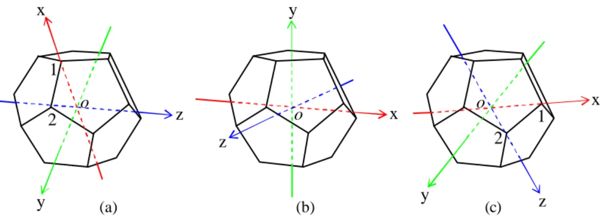
(6) (a). (b). (c). (d). (e). (f). Fig. 2 A typical example to show our algorithm.. When rotating the camera set to a new orientation, all 2D shapes should be rendered from all new cameras position, and the similarity of 2D shapes between each camera pair have to be calculated. This will cause large amount of calculation, and is time consuming. Therefore, we put the camera set in the vertices of a regular convex polyhedron, so that the number of rendering 2D shapes and calculating the similarity between them will be greatly reduced.. vertices. from. five. regular. convex. polyhedrons, as the position of the camera set. There are 20 scattering viewing aspects for each 3D model. The set of 20 2D shapes, rendered from the 20 cameras, is a basis for each 3D model to align between two 3D models, and contains knowledge from various viewing aspects for a 3D model. Fig. 3 explains the reason that we can reduce the number of calculation from rendering and 2D. shapes. matching. by. using. the. dodecahedron. Fig. 3 (a) shows a camera set of model pig, and the same camera set. There are only five regular convex. applying to model cow shows in Fig. 3 (b).. polyhedrons, which are named as Platonic. That is, the indices of camera set are all the. bodies, and was known to the ancient. same between Fig. 3 (a) and (b). In addition,. Greeks. The fact can also be proved using. we can rotate the dodecahedron resulting in. Euler’s theorem. The five regular convex. the camera set is at the same position. For. polyhedrons are tetrahedron, hexahedron or. instance, rotate edge (1,2) from Fig. 3 (b) to. cube,. and. position of edge (1,3) and (1,4), which show. of. in Fig. 3 (c) and (d), respectively. Since a. dodecahedron, which has the maximum. dodecahedron has 20 vertices and each. octahedron,. icosahedron.. We. dodecahedron, take. vertices.
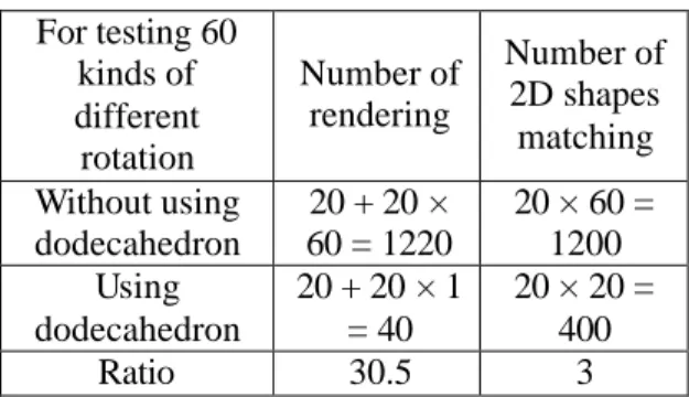
(7) 4. 4 1. 3. 2. 2. 1. 3. 4. 1. 3. (a). 2 1. 2. 3. 4. (b). (c). (d). Fig. 3 We can reduce the number of calculation from rendering and 2D shapes matching by using the dodecahedron. vertex connects 3 edges, there are 60 kinds. There are 60 different rotations to test. of different rotation, which share the same. by using one camera set of dodecahedron. 20 camera positions. Table 1 shows the. for both models. However, it’s usually not. number of rendering and 2D shapes. enough to recover rotation from the best. matching for 60 different rotations with and. solution of the 60 candidates for the coarser. without using dodecahedron. Without using. rotation alignment, Rc. The coarser rotation. dodecahedron, one model should render 20. alignment should provide a good initial, so. times for a camera set, and another model. that the refined rotation alignment, Rr, can. should render 60 camera sets, that is, 1200. easily get the best result from the local. times. The number of rendering can reduce. estimation. Therefore, we can use more. to 40 times by using dodecahedron, 20 times. camera sets from different dodecahedrons.. for each model. On the other hand,. There will increases 60 different rotations. calculation of 2D shapes matching requires. when. 1200 times without using dodecahedron, 20. dodecahedron. If apply one dodecahedron to. times for each rotation. The number of 2D. first model and apply ten dodecahedrons to. shapes. using. another, there will be 600 different rotations.. dodecahedron, because there are 20 shapes. Furthermore, we can also apply more then. for each model. The table shows the reason. one camera set of dodecahedron. That is,. why we use dodecahedron.. when applying m dodecahedron to first. For testing 60 Number of kinds of Number of 2D shapes rendering different matching rotation Without using 20 + 20 × 20 × 60 = dodecahedron 60 = 1220 1200 Using 20 + 20 × 1 20 × 20 = dodecahedron = 40 400 Ratio 30.5 3 Table 1 Number of rendering and 2D shapes. model and n dodecahedron to another, there. matching. is. 400. by. matching for 60 different rotations with and without using dodecahedron.. adding. one. camera. set. of. will be 60×m×n kinds of different rotation. However, the more dodecahedrons are used, the more computation is. Table 2 shows the number of rendering and 2D shape matching by using different dodecahedrons. In our current implementation, we use m=10 and n=10, that is, we take the best one from 6000 different rotations as the coarser.
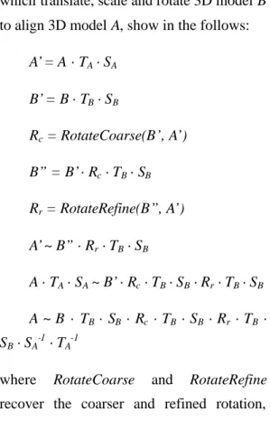
(8) rotation alignment, Rc. The algorithm of. two 3D models A and B, and the operations,. rotation alignment, Rc and Rr, will detail in. which translate, scale and rotate 3D model B. next chapter.. to align 3D model A, show in the follows:. Since. we. use. more. than. one. A’= A ·TA ·SA. dodecahedron, the way to scatter the. B’= B ·TB ·SB. dodecahedrons is also consideration. The purpose is to scatter the camera sets to. Rc = RotateCoarse(B’, A’). whole rotation space, so that any possible. B” = B’·Rc ·TB ·SB. rotation will close to a candidate. If n dodecahedrons should be scattered, we use. Rr = RotateRefine(B”, A’). iterative approach to get the best one by:. A’~ B” ·Rr ·TB ·SB. max ∑∑ MinDist(n, j ) (4) n. A ·TA ·SA ~ B’·Rc ·TB ·SB ·Rr ·TB ·SB. j. A ~ B · TB · SB · Rc · TB · SB · Rr · TB ·. where j is index of dodecahedron vertex, and. SB ·SA-1 ·TA-1. MinDist(n,j) return the minimum. distance from j vertex of n dodecahedron to. where. all vertices of other dodecahedrons. That is,. recover the coarser and refined rotation,. iteratively rotate each dodecahedron from. respectively, and detail in next chapter.. larger to smaller rotation angle, so that all. RotateCoarse. and. RotateRefine. 3. 3D model Alignment in Rotation. vertices of all dodecahedrons are as scattering as possible. The approach is not. This chapter details our approach to. effective, however, the pre-processing stage. align rotation from two models. The rotation. only need to be run once.. alignment divides into two parts: coarse and refined alignment. The coarse alignment. In the end of this chapter, we detail the. gets the approximate rotation from all. operative flow of both models. There are. (m-n) Number of rendering (20× m+20× n) Number of 2D shape matching (20× m×20× n) Number of different rotations (60× m× n). possible orientation between two models.. 1-1. 1-10. 1-20. 1-40. 10-10. 40. 220. 420. 820. 400. 400. 4000. 8000. 16000. 40000. 60. 600. 1200. 2400. 6000. Vertices of scattering dodecahedrons Table 2 Number of rendering and matching 2D shapes are calculated by mapping m to n different dodecahedrons..
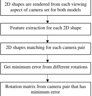
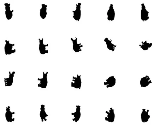
(9) 2D shapes are rendered from each viewing aspect of camera set for both models. determined, the rotation matrix of two models can be obtained by the rotation of the two dodecahedrons. The main flows of coarser and refined rotation alignment are. Feature extraction for each 2D shape. the same. The character of 2D shape depends on. 2D shapes matching for each camera pair. which matching algorithm is used. We use OpenGL to render 2D silhouette by putting Get minimum error from different rotations. camera to vertex of dodecahedron and facing to origin. The size of 2D silhouette is. Rotation matrix from camera pair that has minimum error. 256 by 256 pixels. Since 3D models should. Fig. 4 The flow of rotation alignment. rotation alignment, it’s easier to make sure. be translated, T, and Scaled, S, before that whole 3D models will be rendered into. The refined alignment adjusts approximate. 2D silhouette, that is, no clipping happen.. to. Fig. 5 shows a typical example of 2D. accurate. rotation. from. neighbor. orientation. Since the position and size of. silhouettes. both models are approximate, not exactly. dodecahedron. In our implementation, we. the same, the approach should be invariant. render to screen by perspective projection,. to translation and scaling.. and then use glReadPixels() to copy 2D. We align rotation between two models. from. a. camera. set. of. silhouettes to memory.. by matching 2D shapes form camera set of. To measure the similarity between two. dodecahedron. Fig. 4 shows the flow of. shapes,. rotation alignment. First, 2D shapes should. descriptor of the MPEG-7 [11] to match.. be. of. The matching algorithm can be invariant to. dodecahedron for both models. For each 2D. translation, scaling and rotation in 2D. shape, feature can be extracted for matching. shapes, and allowable of minor non-rigid. later. The operation of rendering and feature. deformations.. extraction do 40 times respectively, if using. descriptor. 1-1 dodecahedron, that is, one camera set of. constituting the shape, so that it can describe. dodecahedron for both models. Then 2D. complex shape including holes and several. shapes of each camera pair are matched, and. disjoint regions. The descriptor utilizes a set. the operation does 400 times if using 1-1. of. dodecahedron. Next, get minimum error. coefficients to describe the shape. The ART. form different rotations, as defined in Eqn.. is a 2D complex transform defined on a unit. (3). Finally, once two camera sets of. disk in polar coordinates. Twelve angular. dodecahedron with minimum error are. and three radial functions are used, and 35. rendered. from. camera. set. ART. we. use. The. makes. (Angular. region-based. region-based use. of. Radial. all. shape. shape pixels. Transform).
(10) Fig. 5 A typical example of 2D silhouettes from a camera set of dodecahedron. ART coefficients of 2D shapes are used for. quantization. is. matching.. coefficients. for. There are several notices for using the 2D shape matching to our approach. In. applied 2D. to. shapes. the. ART. matching.. However, we didn’t quantize the ART coefficients for more accurate.. general, in order to invariant to translation. After feature extraction for each 2D. in pure 2D case, the center of mass in 2D. shape, shape matching for each shape from. shape should be aligned to the center of the. two models is calculated. Number of feature. unit disk. However, our final alignment is in. extraction is the same as rendering, but the. 3D case, so it’s no reason to align the center. number of shape matching is much more. In. for each 2D shape. Since translating 3D. general, the computation of matching is. model to origin has applied before rotation. much less than that of feature extraction in. alignment, we use center of rendered 2D. order to speedy retrieval from a large. shape as the center of the unit disk.. database, since feature can be previously. Furthermore, in order to invariant to scaling,. calculated and saved to database. The. linear interpolation is applied to align. region-based shape matching algorithm use. between rendered 2D shapes from each. simple L1 distance to measure similarity:. viewing aspect and the unit disk. The same as translation, each 2D shapes in a camera set should have the same scaling. Finally,. ShapeDiff (( A, B) ) = ∑ ArtM A [i] − ArtM B [i] (5) i.
(11) where ArtM is the ART coefficients,. aligned if one edge is aligned. We utilize the. ShapeDiff is the same in the Eqn. (3); A and. function of coordinate conversion between. B are two 2D shapes for matching; i is index. the Cartesian and an arbitrary coordinate. of ART coefficients. Therefore, the 2D. system to obtain the rotation matrix. We use. shape matching is speedy.. Fig. 6 to explain our approach. Fig. 6 (a). Next, get minimum error from different rotations of dodecahedron, as defined in Eqn. (3). The error between different rotations is defined as summing distances from all 2D shapes pair of dodecahedron.. and (c) are the dodecahedron pair of model A and B, respectively. The rotation matrix aligns edge (1,2) in Fig. 6 (c) to that in (a). The vector o1 and o 2 can form a unique coordinate frame, defined as follows:. xv = o1 v v v y = z × x zv = o1 × o 2 . For each camera set of dodecahedron pair, there has 60 different rotations. However, there is a little difference in this stage between. coarser. and. refined. rotation. alignment. In coarser rotation alignment, we use 10-10 dodecahedrons, that is, there are 100 kinds of dodecahedron pair, so that 6000 different rotations are tested. In refined rotation. alignment,. we. use. iterative. approach to close the best solution. We start from 10° and step half for each iterative until less than 1°. In each iterative, we adjust rotation of one axis and fix that of another two axes in the order of X, Y and Z axis, respectively. When adjusting rotation of one axis, we rotate the dodecahedron to the direction, which has less error, until no improvement. Therefore, we can align the. where “×” denotes cross produce. The notation FA and FB denote the coordinate system of model A and B, respectively, and FC denote the Cartesian coordinate system. Therefore, the rotation matrix is the coordinate conversion from FB to FA, that is, FBA. However, 3D models are in Cartesian coordinate system, FC, so we cannot apply FBA to model B directly. Model B should be converted to FB coordinate system first and back to Cartesian coordinate system after applying FBA. The rotation matrix is defined as:. rotation with error less than 1°. Finally,. rotation. matrix. (6). FCB ·FBA · FBC =FCB ·FAC · FCB ·FBC. between. =FCB ·FAC. camera set of dodecahedron pair, that has minimum error, should be calculated. The. The FBA can be obtained by FAC · FCB,. rotation matrix is then applied to one model. and FCB · FBC can be eliminated, so the. in order to align rotation to another. The. rotation matrix from model B to model A is. problem of solving the rotation matrix can. FCB ·FAC.. be considered as aligning an edge between two dodecahedrons, because all edges are.
(12) x. y. 1 o. z. 2. (a). 1 2. z y. x. o. x. o. y. (b). (c). z. Fig. 6 Rotation matrix is calculated between two camera sets.. 4. Experimental Results of 3D Alignment In order to experiment with the 3D alignment algorithm, we use 445 models, downloaded from [15] and [16], for initial testing. The alignment algorithm should work well at least using the same models.. In the 445 models, there are 5274.4 vertices and 10233.8 triangles in average. The average execution time for coarser and refined alignments are 25.7 and 39.2 seconds, respectively, in a PC with Pentium III 800MHz CPU, 128MByte RAM and WinFast S680 VGA (S3 ViRGE GX2 chip).. So those models are randomly rotated,. Next, we also test our algorithm by. translated and scaled by another program,. using different models. Those models are. and then using our 3D alignment algorithm. also randomly rotated, translated and scaled. to test. Fig. 7 ~ Fig. 10 show the results, and. by another program first, and then using our. most of them work well. Each model has six. 3D alignment algorithm to test. Fig. 11 ~. pictures. Picture 1 is the original model, and. Fig. 14 show the experiment results. All. picture 2 is the destination model, which. experiment results are available in the web. randomly translate, scale and rotate from. pages:. original model. Picture 3 is the result of. /3dAlign.html.. rotating the destination model to align the original model. To clearly look the relation. http://3dsite.dhs.org/~dynamic. 5. 3D Model Retrieval. of the two models, picture 4 put original and. We apply the technique of 3D model. destination model together. So we can see. alignment to perform 3D model retrieval. In. the difference of translation, rotation and. order to reduce the retrieval time, we move. scaling between two models. Picture 5 and 6. 3D model alignment up to coarser rotation. are the coarsely and refined alignment. alignment stage. That is, the search key of. results between two models, respectively.. 3D models is the ART coefficients from 2D. Fig. 10 demonstrates our algorithm can also. shapes of each camera set. We take the. work well for many separated models.. minimum error between two models as the similar. measurement.. All. models. are.
(13) randomly rotated, translated and scaled by. Processing (ICIP), Thessaloniki, pp.. another program first, and then using our 3D. 935-938, Greece, Oct. 2001.. model retrieval to test. The retrieval time is. [3]. Cha Zhang and Tsuhan Chen,. about 11 seconds in a PC with Pentium III. “Indexing and retrieval of 3D models. 800MHz CPU. Fig. 15 shows several. aided by active learning”, Proceedings. experimental results of 3D model retrieval.. of ACM International Conference on. The. Multimedia, pp. 615-616, Ottawa,. demo. can. be. found. in. http://3dsite.dhs.org/~dynamic/cgi-bin/art/li st.php.. Canada, Oct. 2001. [4]. Ilias Kolonias, Dimitrios Tzovaras, Stratos Malassiotis and Michael G.. 6. Conclusion and Future Works. Strintzis, “Fast Content-Based Search. The paper presents an algorithm of 3D. of VRML Models Based on Shape. model alignment based on a set of 2D. Descriptors”, Proceedings of IEEE. shapes, which are projected from a 3D. International Conference on Image. position, and then applies the technique to. Processing (ICIP), pp. 133-136,. 3D model retrieval. The goal of 3D model. Thessaloniki, Thessaloniki, Greece,. retrieval is to recover coarser affine. Oct. 2001.. transformations first, and is robust against re-meshing,. simplification,. [5]. sub-division,. Robert Osada, Thomas Funkhouser, Bernard Chazelle and David Dobkin. and noise. In the future, other 2D shape. “Matching 3D Models with Shape. matching algorithms can be applied to. Distributions”, Shape Modeling. improve the 3D model alignment algorithm.. International, pp. 154-166, Genova,. In addition, other attributes, such as color. Italy, May 2001.. and texture, can be introduced for 3D model. [6]. retrieval.. Bernard Chazelle and David Dobkin “Shape Distributions”, to appear in. References [1]. ACM Transactions on Graphics, Oct.. Masaki Hilaga, Yoshihisa Shinagawa, Taku Kohmura and Tosiyasu L. Kunii, “Topology Matching for Fully. 2002. [7]. Shape Similiarity-Based Aspect. Shapes”, Proceedings of ACM. Graph”, Proceedings of International. SIGGRAPH, pp. 203-212, Los Angeles,. Conference on Computer Vision. USA, Aug. 2001. Cha Zhang and Tsuhan Chen, “Efficient Feature Extraction for 2D/3D Objects in Mesh Representation”, Proceedings of IEEE International Conference on Image. Christopher M. Cyr and Benjamin B. Kimia, “3D Object Recognition Using. Automatic Similarity Estimation of 3D. [2]. Robert Osada, Thomas Funkhouser,. (ICCV), pp. 254-261, 2001. [8]. Michael Elad, Ayellet Tal and Sigal Ar, “Content Based Retrieval of VRML Objects – A Iterative and Interactive Approach”, Proceedings of 6th.
(14) [9]. Eurographics Workshop on. [15] http://www.3dcafe.com. Multimedia, Manchester UK, Sept.. [16] http://deep.sitenest.net. 2001. [17] http://www.3dfamily.com/products/dig. Eric Paquet and Marc Rioux, “Content-Based Access of VRML Libraries”, Lecture Notes in Computer Sciences, Vol. 1464, pp. 20-32, 1998.. [10] Eric Paquet, Marc Rioux, Anil Murching, Thumpudi Naveen and Ali Tabatabai. “Description of shape information for 2-D and 3-D objects“, Signal Processing: Image Communication, Vol. 16, pp. 103-122, Sept. 2000. [11] Sylvie Jeannin, Leszek Cieplinski, Jens Rainer Ohm and Munchurl Kim, MPEG-7 Visual part of eXperimentation Model Version 7.0, ISO/IEC JTC1/SC29/WG11/N3521, Beijing, China, July 2000. [12] Takeo Igarashi, Satoshi Matsuoka and Hidehiko Tanaka, “Teddy: A Sketching Interface for 3D Freeform Design”, proceedings of ACM SIGGRAPH, pp. 409-416, Los Angeles, USA, Aug. 1999. [13] Guo-Luen Perng, Wei-Teh Wang and Ming Ouhyoung, “A Real-time 3D Virtual Sculpting Tool Based on Marching Cubes”, Proceedings of International Conference on Artificial Reality and Tele-existence (ICAT), pp. 64-72, Tokyo, Japan, Dec. 2001. [14] Szymon Rusinkiewicz, Olaf Hall-Holt and Marc Levoy, “Real-Time 3D Model Acquisition”, proceedings of ACM SIGGRAPH, pp. 438-446, San Antonio, USA, July 2002.. ibox/main.htm.
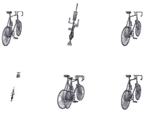
(15) Fig. 7 Results of an experiment by using the same model “3dcafe_ant” among different affine transformations.. Fig. 8 Results of an experiment by using the same model “3dcafe_bicycle” among different affine transformations..
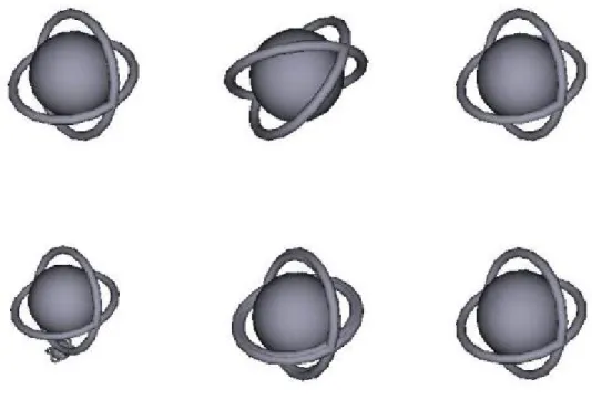
(16) Fig. 9 Results of an experiment by using the same model “3dcafe_orbit” among different affine transformations.. Fig. 10 Results of an experiment by using the same model “3dcafe_fishbird” among different affine transformations. Our algorithm can work well for separated models..
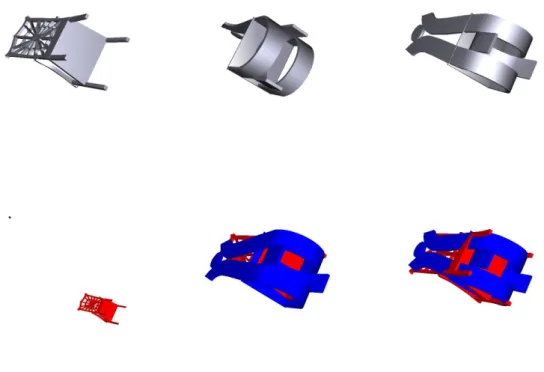
(17) Fig. 11 Results of an experiment in aligning model “3dcafe_chair01” to model “3dcafe_chair”.. Fig. 12 Results of an experiment in aligning model “3dcafe_cow” to model “3dcafe_pig”..
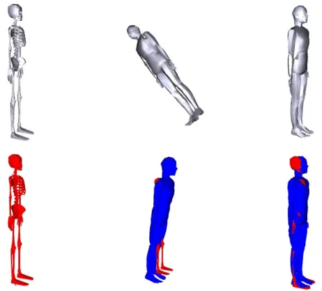
(18) Fig. 13 Results of an experiment in aligning model “3dcafe_man1” to model “3dm-mc_slim”.. Fig. 14 Results of an experiment in aligning model “3dcafe_dc10” to model “3dcafe_a-10”..
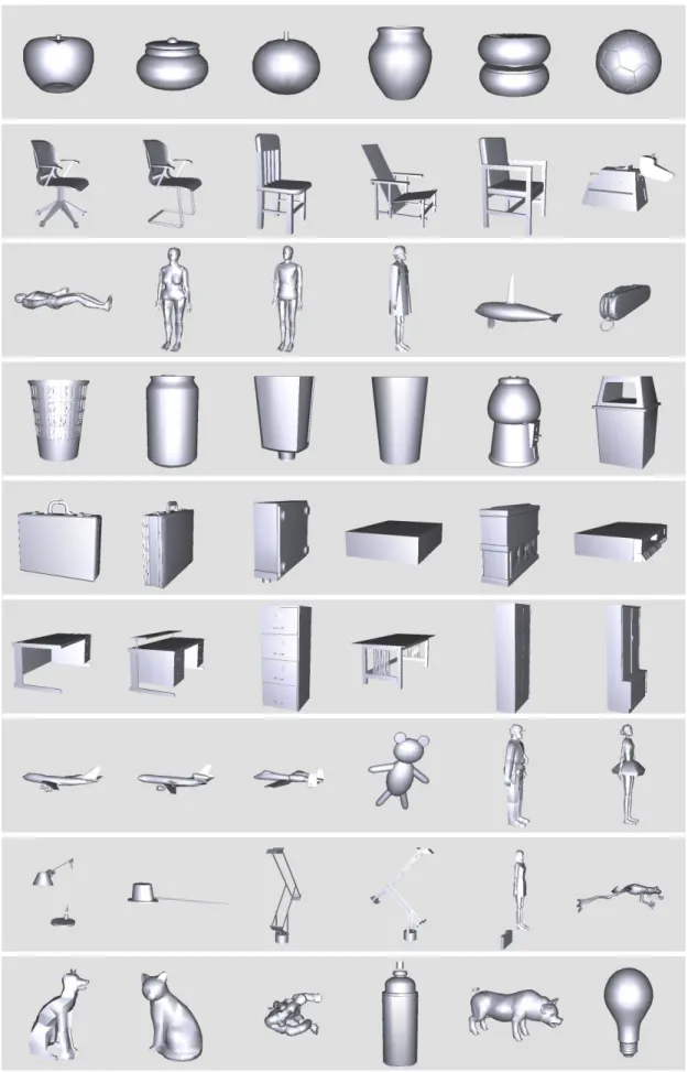
(19) Fig. 15 Experimental results of 3D model retrieval. The first one of each row is the target to be queried. The top 7 similar models are ranked from left to right.
(20)
數據
+7
相關文件
Field operators a † ↵, (q) and a ↵, (q) create or destroy a photon or exciton (note that both are bosonic excitations) with in-plane momentum q and polarization (there are
• Given a direction of propagation, there are two k values that are intersections of propagation direction and normal surface.. – k values ⇒ different phase velocities ( ω /k)
• A way of ensuring that charge confinement does occurs is if there is a global symmetry which under which quarks (heavy charges) are charged and the gluons and other light fields
These are quite light states with masses in the 10 GeV to 20 GeV range and they have very small Yukawa couplings (implying that higgs to higgs pair chain decays are probable)..
It is useful to augment the description of devices and services with annotations that are not captured in the UPnP Template Language. To a lesser extent, there is value in
- - A module (about 20 lessons) co- designed by English and Science teachers with EDB support.. - a water project (published
There is no general formula for counting the number of transitive binary relations on A... The poset A in the above example is not
In outline, we locate first and last fragments of a best local alignment, then use a linear-space global alignment algorithm to compute an optimal global
