國立交通大學
光電工程研究所
博士論文
液晶透鏡於行動裝置之成像應用研究
Liquid Crystal Lenses for Imaging Application in
Mobile Devices
研究生:廖凌嶢
指導教授:黃乙白
ii
液晶透鏡於行動裝置之成像應用研究
Liquid Crystal Lenses for Imaging Application in
Mobile Devices
研 究 生:廖凌嶢
Student:Lin-Yao Liao
指導教授:黃乙白
Advisor:Yi-Pai Huang
國 立 交 通 大 學
資 訊 科 學 系
碩 士 論 文
A Thesis
Submitted to Institute of Electro-Optical Engineering College of Electrical Engineering and Computer Engineering
National Chiao Tung University for the Degree of Doctor of Philosophy
in
Department of Photonics September 2011
Hsinchu, Taiwan, Republic of China
液晶透鏡於行動裝置之成像應用研究
學生:廖凌嶢 指導教授:黃乙白
國立交通大學光電工程學系﹙研究所﹚博士班
摘要
行動手持裝置已成為日常生活中不可缺少的電子用品,而手持裝置裝中
的攝像鏡頭,往往成為在執行攝影、影像辨識、電腦視覺以及影像溝通時
重要元件。在諸多的光學元件中,液晶透鏡由於擁有電控式變焦以及體積
小等特點,泯除傳統機械式移動的特性,充分展現應用於體積輕巧的行動
手持裝置優勢。然而,液晶透鏡目前仍無法克服的缺點,諸如較差的影像
品質、反應速度過慢以及不切實際的高驅動電壓,都大大地降低液晶透鏡
的實用性。
在本論文中,我們首先針對液晶轉角不易精準控制的問題,提出多電及
控制結構,藉由多電擊的高控制自由度,可更精準控制液晶層轉角分布,
以提高聚焦品質。在此項研究項目中,我們也實現了針對不同焦距給定不
同電壓組的最佳化控制。第二,我們提出突破性的液晶透鏡控制結構—漸
變式驅動液晶透鏡,在此項目中,我們應用高電阻層做為控制電極,不但
能夠充分利用施加之電場,亦可創造出漸變性的電壓分布,一方面大大將
控制電壓從原本的幾十伏特甚至上百伏特降低至五伏特以內,搭配爾後本
團隊發展出來針對液晶透鏡的加強驅動方式,將原本大於三十秒以上的反
應速度將低至六百毫秒內,這對液晶透鏡發展領域無疑是突破性的發展,
再者,由於電阻及液晶層猶如一層
RC 電路,所以頻率上的可控制性,亦延
續了先前多電極控制這種高自由度的控制概念,來提升聚焦品質。在論文
iv
Liquid Crystal Lenses for Imaging Application in
Mobile Devices
Doctoral Student: Lin-Yao Liao
Advisor: Dr. Yi-Pai Huang
Institute of Electro-Optical Engineering
National Chiao Tung University
Abstract
Mobile devices become necessary products for daily life’s use in recent years. When perform functions of photography, phantom identification, computer vision, and image communications, lens-heads play an important role to deal with the basic function of imaging. Liquid crystal (LC) lens has unique properties such as electrically tunable focal length. Since there are no moving mechanical parts, LC lens is smaller and lighter than conventional tunable glass lenses. In mobile devices, LC lens can directly combine with mobile lens-module in front of the lens-head, and easily perform auto-focusing (AF) function by driving appropriate voltage to focus objects at different distances. However, inferior optical quality, slow focusing time, and high driving voltage are current major issues of LC lenses’ study. These drawbacks make LC lenses unpractical and unfeasible in real usage for mobile devices.
In this thesis, we first started from Multi-electrode Driven LC lens (MeDLC lens) to precisely control profiles of LC lens for different focal length. By the multi-electrode, we demonstrate highly controlled freedom for modifying the index distributions for each focal length to obtain similar and superior focusing profiles. In the second part, Gradient-driven LC lens (GDLC lens) was proposed to intrinsically improve the driving efficiency. We utilized a
resistance layer connected with electrodes as the control layer. The benefit of this structure is that the applied electric field can be efficiently employed and a gradient distribution in voltage can be produced. By GD-LC lens, the driving voltage typically higher than tens root-mean-square voltages was reduced down to less than 5Vrms for imaging 6cm closed objects. In the third part, Over-drive (OD) method for LC lenses was proposed to investigate focusing behavior. A switching operation in this method according to the focusing profile was used to reduce the focusing time. Performing with GDLC lens, we yielded 600msec focusing time by a LC lens with 60um cell gap and 2mm aperture size for capturing the 6cm objects. By combining these results, we not only dramatically improved the performance for current LC lenses but also to break through the issues of the current studies. Our outcome, furthermore, make the use of LC lenses for commercial mobile devices more feasible and practical.
vi
誌
謝
回想起第一次與指導教授 黃乙白老師會面,約的居然是在 田仲豪老師的辦公室, 當時黃老師還是新進教師,沒有自己的地盤,只能在下班後趕往交大與我面談,也因此 展開了研究所的生涯。但回顧起博士班的開始,應該是剛到實驗室的第一天,當初黃老 師詳盡地介紹實驗室,也見識到了 謝漢萍老師不怒而威的霸氣,而後從 韋安琪學姊口 中知道 黃乙白老師也是實驗室直升的博班生,於是也動起了直升博班的念頭,但真正 的臨門一腳,是在一次實驗室的 meeting 中見到 楊柏儒學長以流利的英語跟大夥報告 著他的研究成果,心中驚嘆:哇~博士班果然要接受不同於凡人的訓練啊。抱持著"吃 得苦中苦"的心態,於是踏入了博士班這趟旅程。 剛進入這個大家庭,起初跟著 林芳正學長學習做 HDR 的相關題目,回想起那段成 天跑 AUO 開會,開完會連同 廖振宇學長到附近的麵館吃麵的日子,己腸轆轆伴隨著 汪 德美主管給予的壓迫帶來的愁容,雖是研究生卻有如工程師一般。最後,大夥的成果發 表成了論文,也因為這篇論文,我第一次到了美國,到了洛杉磯,到了拉斯維加斯,研 究所的初體驗是如此精彩而充實。 正式進入博士班以後,著手於液晶透鏡的研究,這是個有趣而不那麼容易的的題目。 我開始進到無塵室,展開沒日沒夜的製程工作,泛黃的燈光灑在冰冷的機台,靜默的工 作區偶爾夾雜著擾人的機器聲響,心裡想著,這彷彿不是我想像中的博士生涯,抗拒的 心理也隨之而來。就在萬念俱灰之際,慶幸地,許多努力的學弟妹們一起加入奮鬥,讓 我們困難的工作出現了轉機,無論是李俊賢學弟、陳致維學弟、沈拓江學弟、以及後來 紛紛加入的林裕閔學弟、黃怡菁學妹、陳博詮學弟等,都努力的投入,沒有你們,也許 我早早就撐不下去了。 但最讓我嘗到研究的甜美成果的,無非是和謝博元(博六)學弟以及陳禹辰(小發特) 學弟所組成的三人 Group 的研究期間吧,博六的細心謹慎加上小發特的大鳴大放,著實 讓我們的研究成果產生了極大的火花,短短幾年的研究,成果已經趕上了國際知名團隊,
甚至超越。永遠忘不了第一片鍍上高阻層液晶透鏡聚焦成像的那一天,也忘不了大夥常 常準備到半夜,為了隔天某某國際大咖將親臨觀賞我們的展示,諸多人的努力與配合, 成就了那不到 1 秒的快速聚焦! 如今我在亞利桑那光學中心,寫下這份誌謝,心中萬分的感激與感嘆,就是這四五 年之間,讓身邊的人事物以及所見所聞如此不同,感謝奶奶以及家人們長期的支持,感 謝我的未婚妻朱苑爾的陪伴,感謝好友林柏瑋一起到香港看 coldplay,學姊 蔡韻竹、 學長 許精益常在 meeting 時一起嘴砲,以及資格考三人組的另外兩員猛將簡上杰、蔡 武衛的一起衝刺並在資格考結束當天衝去吃羊肉爐,學長 林淇文在實驗上的大力幫忙, 更要感謝實驗室所有學長姐、學弟妹的指教,沒有你們的幫忙,我無法完成這本論文, 最最最重要的,要感謝我的指導教授黃老師,感謝您在背後無限的奧援、信任與支持。 謝謝!! 常常懷念起謝老師說的:「技術方面的學習都不是大問題,重要的是要把英文學好。」 現在真的深深體會這句話,也唯有充分的溝通,才能讓自己”Presentable”吧!
viii
Contents
CHAPTER 1. INTRODUCTION ... 1
1.1 TUNABLE-FOCUS LENSES ... 1
1.2 LCLENSES ... 3
1.3 COMPARISON OF SINGLE-TUNABLE LENSES ... 7
1.4 LENS-HEADS IN MOBILE DEVICES ... 8
1.4.1 Auto-focusing (AF) ... 9
1.4.1.1 Voice Coil Motor (VCM) ... 9
1.4.1.2 Extended Depth-of-field (EDoF) ... 11
1.4.1.3 LC Lenses ... 12
1.4.2 Optical Zoom ... 13
1.5 MOTIVATION AND OBJECTIVE OF THIS THESIS ... 15
CHAPTER 2. THEORY AND PRINCIPLE OF LC LENSES ... 17
2.1 INTRODUCTION TO LIQUID CRYSTALS ... 17
2.2 ENERGIES IN LCCELLS ... 18
Elastic Energy ... 19
Electric Field ... 20
Anchoring Effect ... 21
2.3 OPTICAL PRINCIPLE OF LCLENSES ... 22
CHAPTER 3. MULTI-ELECTRODE DRIVEN LC LENS ... 26
3.1 INTRODUCTION ... 26
3.2 MULTI-ELECTRICALLY DRIVEN LIQUID CRYSTAL LENS (MEDLCLENS) ... 27
3.2.1 MeDLC Lens ... 27
3.2.2 Optimization ... 28
3.3 EXPERIMENTAL RESULTS ... 31
3.4 DISCUSSION -GRATING STRUCTURE OF MED-LCLENS ... 34
3.5 CONCLUSION ... 36
CHAPTER 4. GRADIENT DRIVEN LIQUID CRYSTAL LENS EXHIBITING ULTRA-LOW OPERATING VOLTAGES ... 37
4.1 INTRODUCTION ... 37
4.2 GRADIENT DRIVEN LIQUID CRYSTAL LENS (GD-LCLENS) ... 40
4.2.1 Concept ... 40
4.3 EXPERIMENTAL RESULTS ... 46
4.4 PHASE RETARDATION OF CONVEX AND CONCAVE MODES ... 49
4.5 CONCLUSION ... 52
CHAPTER 5. OVER-DRIVE METHOD FOR FAST FOCUSING LIQUID CRYSTAL LENS ... 53
5.1 INTRODUCTION ... 53
5.2 OVER-DRIVE METHOD FOR LCLENS ... 54
5.3 3-DIMENTIONAL IMAGING AND ANALYSIS FOR LCLENSES BY FLUORESCENCE CONFOCAL POLARIZING MICROSCOPY ... 58
5.3.1 3-D Imaging of LC lenses ... 59
5.3.2 Phase retardation ... 63
5.4 EXPERIMENTS AND OPTIMIZATION OF OVER-DRIVING VOLTAGES ... 66
5.5 CONCLUSION ... 69
CHAPTER 6. AF IMAGING WITH SPHERICAL GD-LC LENS ... 70
6.1 INTRODUCTION ... 70
6.2 FABRICATION ... 70
6.3 OPTICAL PROPERTIES OF SGD-LCLENS ... 72
6.4 AFEXPERIMENT WITH SGD-LC LENS ... 75
6.4.1 Experimental Principle ... 75
6.4.2 Results ... 79
Resolution Test Chart for different focal length ... 79
AF test ... 81
MTF measurement ... 82
6.5 CONCLUSION ... 84
CHAPTER 7. CONCLUSION AND FUTURE WORK ... 85
7.1 CONCLUSION ... 85
7.1.1 Multi-electrode Driven LC Lens (MeDLC Lens) ... 85
7.1.2 Over-driving (OD) Method for LC lenses ... 86
7.1.3 Gradient Driven Liquid Crystal Lens (GD-LC lens) ... 87
7.2 FUTURE WORK ... 89
7.2.1 Optical design for LC lens ... 89
7.2.2 Polarizer free LC lens ... 90
7.2.3 Optical Zoom ... 91
REFERENCE ... 94
x
Figure Captions
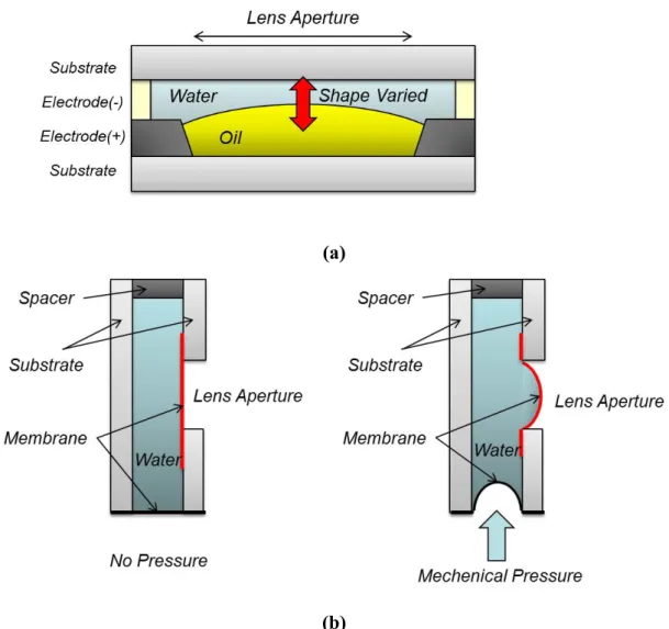
Figure 1-1 (a)The liquid lens employs the oil-water surface and electrically control the surface shape. (b) The liquid lens mechanically controlled the
membrane shape to focus the light. ... 2
Figure 1-2 The world first LC lens proposed by Prof. Susumu Sato ... 3
Figure 1-3 The typical structures controlled by inhomogeneous field with an inhomogeneous layer on (a) short focusing state, and (b) long focusing state. ... 4
Figure 1-4 The typical structures controlled by inhomogeneous field with an homogeneous LC layer. ... 4
Figure 1-5 Two of the most general homogeneous LC Lenses, (a) the structure with external electrodes, and (b) the structure with internal electrodes utilizing electrical fringe field of the electrodes to generate a gradient variation in phase retardation. The low freedom of electrical control limits the range of focusing. ... 6
Figure 1-6 Structure of conventional VCM actuator. ... 10
Figure 1-7 The focusing mechanism of VCM approach. ... 10
Figure 1-8 The principle of EDoF method. ... 12
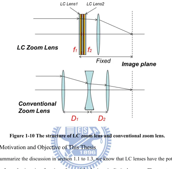
Figure 1-9 The mechanism of LC lens used for AF function in mobile device.13 Figure 1-10 The structure of LC zoom lens and conventional zoom lens. ... 15
Figure 2-1 The phases of LCs under different range of temperature ... 18
Figure 2-2 The three possible forms of deformation, (a) splay, (b) twist, and (c) bend, of nematic LCs. ... 19
Figure 2-3 LC directors, , which indicates the directions of LC molecules in Cartesian coordinate ... 20
Figure 2-4 The field was decomposed into two perpendicular directions along and perpendicular to . ... 21
Figure 2-5 Three of the common alignment methods, (a)perpendicular, (b)anti-parallel, and (c)parallel alignments for LC cells. ... 22
Figure 2-6 The ordinary and extraordinary lights travelling in the LC material and extraordinary lights see the different indies which are dependent to the included angles between the incident light and the optical axis of LC molecules. ... 23
Figure 2-7 The wavefront focusing of LC lens. ... 24
Figure 2-8 The diagram of LC lens considered as a GRIN lens for analyzing the focusing. ... 25 Figure 3-1 The focusing profile of the homogeneous LC lens with different
focal length, 4cm and 10cm. The focusing profiles are different. ... 27 Figure 3-2 MeD-LC Lens with large number of electrodes. MeD-LC Lens
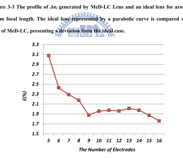
utilized the arrangements of driving voltages to finely control the LC orientation, and yielded a wide range of superior focusing ... 28 Figure 3-3 The profile of Δnl generated by MeD-LC Lens and an ideal lens for
around 3.5cm focal length. The ideal lens represented by a parabolic curve is compared with that of MeD-LC, presenting a deviation from the ideal case. ... 30 Figure 3-4 The quantified errors, E, representing the deviation of the results of
MeD-LC from the parabolic curve, is utilized to optimize the number of electrodes for MeD-LC Lenses. ... 30 Figure 3-5 The optimized driving voltages for 9-electrode MeD-LC Lens in
convex applications. The symmetrical arrangement of each driving voltage was adjusted for particular focal length. In convex MeD-LC Lens,
marginal voltages are higher than central voltages to form convex-like phase retardation. ... 32 Figure 3-6(a) Cylindrical MeDLC Lens measured by CCD sensor at a distance
of corresponding focal length (EF), and (b) the focusing profile were compared with two conventional LC lens. As the results shows, two
conventional LC lenses only yielded a particular range of focusing. On the other hand, the multi-electrode of MeDLC Lens served the LC layer optimized phase retardation for each focal length and a wide range of focusing. ... 33 Figure 3-7(a) The focusing profile of MeD-LC Lens without coating PMMA
and (b) coating with PMMA for suppressing the intensity of side lobes. The large side lobes of focusing profile due to the grating structure of MeD-LC raised undesired cross-talk effect. The coating material with approximate reflective index can effectively reduce the side lobes. ... 35 Figure 4-1 The simulations of electric field for four kinds of homogeneous LC
lenses including internal and external electrodes with two and multi controls. ... 39 Figure 4-2 The structure of internal continuous electrode performs a smooth
gradient electrical field and can conserve the electrical energy inside the LC layer. The simulation work was done by using 2DimMOS. ... 40 Figure 4-3 The testing device of LC cell with high resistance layer connected by
xii
ΔV=5Vrms. The LC cellwas design by 60μm cell gap driven by the two controllingelectrodes with 2mm separation. ... 41 Figure 4-5 The configuration of GD-LC Lens. The structure with 2mm lens
aperture and 60um anti-parallel LC cell gap was constructed by
combining triple internal electrodes with the high resistance layer. ... 42 Figure 4-6 The schematic of resistance of the controlled high R layer. ... 43 Figure 4-7 The schematic of induced polarizations by z direction electric field.
... 44
Figure 4-8 The simulated voltage distribution and corresponding phase retardations, the region which applying voltage under threshold value cannot distorted the LC directions. In other words, the model only
considering the configuration as transmission line and driven by uniform electric may miss the accuracy of complete electrical field simulations. . 45 Figure 4-9 The focusing profile of GD-LC Lens drivenat (a) V=0, and (b)
V=2.35Vrms@2.4kHz for 5cm focal length. ... 47 Figure 4-10 The relationship of focal length to operating voltage and frequency
of GD-LC Lens. ... 48 Figure 4-11 The focusing profiles of GD-LC lens at different focal length from 2.5cm to 10cm controlled by voltage and frequency. ... 49 Figure 4-12 The phase retardation of GD-LC Lens operated in (a) convex, and
(b) concave modes. By the different operating arrangement, both convex and concave lenses were achieved. ... 51 Figure 5-1 (a) General structure of homogeneous LC Lens driven by marginal
over-drive voltages, and (b) The curve of focusing response time to normalized intensity on CCD sensor for a particular focal length. The over-drive voltages yielded a initial focusing as shown the first peak. .... 55 Figure 5-2 The variation of focusing intensity with time driven by OD method and general driving was measured by CCD sensor. ... 57 Figure 5-3 The results of OD method by different switching time. The
switching at the time approximated to the initial focusing can obtained the shortest focusing time. ... 57 Figure 5-4 The diagram of the fluorescence confocal polarizing microscopy
system. ... 59 Figure 5-5 The setup of measure by FCPM. ... 60 Figure 5-6 (a) The scanned result before applying driving voltage, and (b) ~ (d)
that of scanned layers after driving. ... 60 Figure 5-7 The contours indicating the refractive index and LC tilt angle of
Figure 5-8 The 3D diagram of LC profile. ... 63 Figure 5-9 The phase retardation calculated by (a) FCPM method and (b)
measured by fringing pattern approach. ... 65 Figure 5-10 The cross sections of phase retardation for 5 cm focal length by
FCPM method and fringing pattern approach, as well as the ideal curve.
... 66
Figure 5-11 The result of relation between focusing time and OD voltages. Improvement was saturated as the voltage was larger than 65Vrms. ... 67 Figure 5-12 (a)The structure of GD LC lens with multi-electrically control, and
(b) the relation of response time to over-drive voltages. ... 69 Figure 6-1 The electrode patterns of (a) cylindrical and (b) spherical GD-LC
lens. ... 71 Figure 6-2 The double-layer electrode structure of sGD-LC lens employing an insulator to separate the electrode layers. ... 72 Figure 6-3 The structure of GD-LC lens. ... 72 Figure 6-4 The focusing profile of sGD-LC lens driven by 3.3Vrms at 4.22 kHz.
... 73
Figure 6-5 The focusing profiles of sGD-LC lens from focal length, 7cm~15cm.
... 74
Figure 6-6 The relationship between of focal length to operating voltage and frequency of sGD-LC Lens. ... 74 Figure 6-7 The schematic of lens-system with and without LC lens. ... 76 Figure 6-8 (a)The setup of lens-system and (b) the experimental arrangement.
... 77
Figure 6-9 (a)The function of control signal and (b) the equipmet. ... 78 Figure 6-10 The test chart placed in front of sGD-LC lens at the distance
corresponding to the focal length. ... 79 Figure 6-11 The results of test chart for different focal length ... 80 Figure 6-12 The AF experiment and the toys placed at different distances. ... 81 Figure 6-13 (Video) The AF result of four toys at different distances, and OD
result focusing from the farest toy to the nearest one. ... 82 Figure 6-14 MTF of sGD-LC lens measured by ImageMaster® HR, Trioptics.
... 83
Figure 7-1 The relations of the topics for each issue ... 85 Figure 7-2 The change of LC lens structure from conventional single control to
xiv
Figure 7-4 The dramatic improvement in driving voltage and focusing time with GD-LC lens combined with the volt. & freq. dual-control and OD
method. ... 88
Figure 7-5 The relation of lens design tool for LC lens design ... 90
Figure 7-6 The concept of DIP for polarizer free LC lens. ... 91
Figure 7-7 The schematic of LC zoom lens ... 92
Figure 7-8 The variation of lens power, K, changed by LC lens power, K1 and K2 ... 93
List of Tables
Table 1 The comparison of LC lenses proposed by the world leading groups.
... 7
Table 2 The spec. list of conventional VCM. ... 11 Table 3 The comparison of three AF solution for mobile devices. ... 16
Table 4 The comparison of focusing time and corresponding operating voltage. The result shows GD-LC Lens significantly improved driving voltage and only can be only driven by less than 5Vrms. ... 52 Table 5 The results and comparisons of two main structures of LC lenses
driven by OD method. In the internal structure part, focusing response time was reduced to 0.2sec by 15Vrms over-drive voltage. ... 68 Table 6 The comparisons of single tunable lenses. ... 89 Table 7 The comparison of the AF solutions after the improvements of our
1
Chapter 1.
Introduction
1.1 Tunable-focus Lenses
Lenses are key elements of optical systems. Most of the conventional lenses are made of glass, polymer, or other transparent solid materials, which exhibits fixed focal length. A lens system with tunable-focus can be achieved by adjusting the distance of two or more lenses. This approach for Auto-focusing, or Zoom function in imaging systems has been wildly utilized, and the theory for optimization of imaging aberrations are also developed. Zoom Lenses, for example, adjust the positions of lens groups to varied the effective focal length and simultaneously compensate the deviation of imaging plane to the position of image sensor. Another option in actuator technology, voice-coil motor (VCM) [1-5], is used combining with lens-head for the auto-focusing in cellphones. The motor controls the position of whole lens module to image objects at different positions, but the lens groups is difficult to be individually controlled duo to the size and tolerance limitation. Therefore, these approaches either make the devices bulky and heavy or only can perform simple functions due to the spacing or a number of components. In many consumer products, slim and light would be the key concern, especially in mobile devices.
Single tunable lens already exist in nature. Human eye is one of the single-lens systems with a tremendously wide tunable focal range. The primary tuning mechanism is shape change, as controlled by the muscles in the eye. To mimic the fovea imaging of the human eye, similar technologies was proposed to change the material’s shape, including liquid lenses [6-13], or microfluidics lenses [14-18]. General liquid lenses are constructed by an interface between two different materials. These materials can be air-to-water or two different liquid materials (water-to-oil, for example) [19-24]. Electrically or mechanically control the shape of
the interface; we can vary the lens power, and shown in Figure 1-1(a) (b). The issues of this technology are the environmental limitations, such as gravity or low feasible range of temperature.
(a)
(b)
Figure 1-1 (a)The liquid lens employs the oil-water surface and electrically control the surface shape. (b) The liquid lens mechanically controlled the membrane shape to focus the light.
Polymer and liquid crystal (LC) are also material for single tunable lens. Instead of the shape changing, stressed polymers and LC are examples of using refractive index change. For current applications, LC is wildly utilized for Spatial Light Modulators (SLMs) [25-34], one
3
that the refractive index is sensitive to electrical control. Its stability also favors the industrial fabrications. Therefore, LCs is a unique and suitable material for single tunable lenses.
1.2 LC Lenses
LC employed for lens application was firstly proposed in 1979 [37]. Prof. Susumu Sato prepared the concave and convex glass lenses covered by the transparent substrate, and injected Liquid crystal into the cavity, as shown in Figure 1-2. By the electrical control, the optical power can be changed without shape changing. In the both cases, the refractive index of glasses was well-chosen, and the operating voltage can change the orientation of LC to control the incident light. Of course, polarizers in front of the lenses are necessary to yield polarized light.
Figure 1-2 The world first LC lens proposed by Prof. Susumu Sato
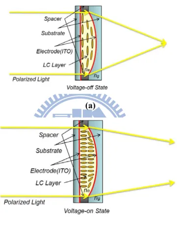
Prof. Shin-Tson Wu further classified LC lenses into the structures of inhomogeneous and homogeneous LC layer controlled by inhomogeneous or homogeneous electrical field respectively [38-41]. Two of the typical structures controlled by inhomogeneous field are shown in Figure 1-3 and Figure 1-4. In the inhomogeneous layer, the LC are sandwiched between substrates, one of which are a concave substrate deposited an indium-tin-oxide (ITO)
electrode. In the voltage-off state, the effective refractive index of LC material is driven as ne.
By a well-chosen ng of the glass which is smaller than ne, the LC lens is driven to a convex
lens with a shorter focal length. Compared to the mode of voltage-on state the index of LC
On the other hand, the homogeneous layer, LC is sandwiched between a flat bottom substrate and a top planar-concave glass. To fabricate such an LC lens, the plano-concave glass is prepared with an appropriate curvature. The concave surface is coated with ITO as the control electrode, as shown in Figure 1-4. The bottom substrate, as well as, is coated with ITO layer to form the inhomogeneous electrical field. Two of the driving voltage applied on the ITO electrodes can generate different orientation of LC.
(a)
(b)
Figure 1-3 The typical structures controlled by inhomogeneous field with an inhomogeneous layer on (a) short focusing state, and (b) long focusing state.
5
There are also combined structures which including the homogeneous LC layer and inhomogeneous structure to yield non-uniform electrical field [42]. It utilizes an inhomogeneous glass lens sandwiched between two homogeneous electrodes, the gradient electrical field can be generated, although the flat structure of ITO and LC layers. Other approaches for LC lenses were also proposed, such as polymer type and other novel approaches [43-51].
A simplest structure of LC Lenses is utilizing the electrical fringe field to control the orientation of LC. This structure is typically constructed by two flat substrates clipping a homogeneous LC layer. The ITO electrodes on the substrates can be patterned to yield the fringing field. Prof. Shin-Tson Wu also discussed eight different types of this kind of LC Lenses [52]. In this kind of homogeneous LC Lens, the patterns of electrodes and electrical control are critical for yielding the desired phase retardation on uniform LC layer. Two of the homogeneous LC Lenses are shown in Figure 1-5 (a) (b), structures with external and internal electrodes, both of which utilize the fringe field of the electrodes to control the phase retardation of the LC layer. The electrodes are typically constructed of ITO. The difference of these two structures is the insertion of high K material (i.e. the substrate) between two ITO layer, which the function is to smooth electric field communicated to the LC layer. This kind of structure is effective, simple, and also easy for realizing spherical and cylindrical LC Lenses. In order to have the benefit of simple structure and more flexible for applications, our studies focused on this kind of LC lenses.
(a)
(b)
Figure 1-5 Two of the most general homogeneous LC Lenses, (a) the structure with external electrodes, and (b) the structure with internal electrodes utilizing electrical fringe field of the electrodes to generate a gradient variation in phase retardation. The low freedom of electrical control limits the range of focusing.
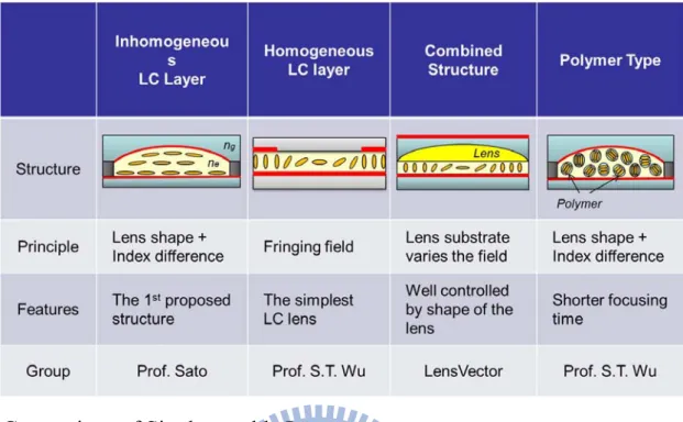
To summarize these structures for LC lens, a comparison lists the representative structures, as in Table 1. Typically, the principle of these types is employing the inhomogeneous LC layer or non-uniform electric field to yield lens-shape gradient index distributions.
7
Table 1 The comparison of LC lenses proposed by the world leading groups.
1.3 Comparison of Single-tunable Lenses
In the previous sections, two kinds of single-tunable lens, liquid and LC lens were discussed. In the liquid lens part, it is a shape changed system to control the incoming light, which also means the requirement of more complicate structure for controlling the surface between two liquid materials. As the result, the structure is relatively bulky than that of LC lens. Furthermore, from the reports of newly papers, the shape of liquid is usually difficult to be changed. For example, the variation of the surface requires ultra-high voltage. Besides, issue of gravity also results in lateral deviation of its optical axis. On the other hand, LCs has the unique feature which is sensitive to electric field. LCs can be driven by low driving voltage and the orientation can be easy controlled to change the phase retardation. This feature is also the reason LCs have been wildly used in LCD industry. Therefore, the easy driving and simpler structure is the why we choose LC lens as the device for imaging application in mobile devices. However, the optical property and the use of polarizer make LC lens have intrinsic limitation for lens applications. For the optical property part, the inhomogeneous refractive index of LCs results in difficulty for optical analysis. Therefore, LC lens cannot be
analyzed by the shape of a lens which is principle of optimizations for conventional lens-head and also is feasible for liquid lenses. This also means we cannot use available lens design tool for the optimization of LC lens. On the other hand, the use of polarizer in LC lens reduces a half of incoming light efficiency. The loss of light efficiency changes cognition of f-number (F/#) which is used to describe light efficiency of a lens-head, and may result in requirement for larger aperture size for keep the same efficiency.
To summarize the above comparison, Table 2 lists the advantages and disadvantages of liquid and LC lens. LC lens shows the intrinsic benefit, such as easy control, simple structure, and no gravity issues, which are more convenient for fabrication and applications in mobile devices. For the last to issue, optical analysis and use of polarizer, these can be overcome by linking simulation tools for LC cell and lens-head design and utilize image processing to eliminate information from ordinary-ray, which will be discussed in last part of the thesis.
Table 2 The comparison of two single-tunable lens, liquid and LC lens.
1.4 Lens-heads in Mobile Devices
Mobile devices become the necessary produces for daily life’s usage in recent years, especially when communication technology is growing up fast. Lens-heads are key components in the devices, such as cellphones, laptops, and tablet PCs. When performing functions of photography, phantom identification, computer vision, and image communications through these devices, lens-heads always play an important role to deal with
9
face the challenge to minimize the thickness of lens modules as these devices are required to be slimmer and slimmer. Not only the simple imaging function, but also technologies of auto-focusing (AF) and optical-zoom are also diligent directions for improving the image quality. For the improvement of image quality, tree of the AF technologies for imaging objects at different distances are developed.
1.4.1 Auto-focusing (AF)
1.4.1.1 Voice Coil Motor (VCM)
Voice Coil Motor (VCM), as mentioned in section 1.1, is one of the approaches to perform AF in mobile devices. The principle of VCM is the same as a loudspeaker exciting its voice coil with a controlled current to vibrate its diaphragm. In the application of AF, the VCM actuator consists of two main parts, the fixed permanent magnets and the moving lens-holder coiled coil, as shown in Figure 1-6. To actuate a lens-head, the positive and negative Lorentz force can be yielded by different direction of driven currents. The equation illustrates the relation following:
∙ ∙ (1-1)
where , , , , and indicate Lorentz force, the number of coil, the length of coil
vertical to direction of magnetic field, driven current, and magnetic flux density respectively. Moving the lens-head, VCM method can shift the image plane to the position of image sensor for focusing objects at a finite distance, as shown in Figure 1-7. Therefore, it is an effective approach to perform AF in such a limited space of mobile devices, and one of the mainstreams for current solutions for AF. However, the size of VCMs is generally larger than that of lens-heads for embedding the lens-heads, as Table 3 shows the fundamental spec. and appearance of VCM products of TDK Xiamen CO., LTD [53]. Cost is also increased due to the additional VCM module and the integrations. Furthermore, for such a limited space (generally required to less than 5mm) in mobile devices, only one VCM is usually used to actuate the whole lens-head instead of the individual lenses. As a result, only one variable can
be changed to perform AF by adjusting the relative distances of object and image, not mention to other functions such as zoom.
Figure 1-6 Structure of conventional VCM actuator.
Figure 1-7 The focusing mechanism of VCM approach.
11
Table 3 The spec. list of conventional VCM.
1.4.1.2 Extended Depth-of-field (EDoF)
Another technology, Extended Depth-of-field (EDoF) a novel computational imaging approach for extending the Depth-of-field (or Depth-of-focus) of fixed-focus mobile lens [54-59]. Utilizing a phase mask combined with lens-head, the system can generate similar Point Spreading Functions (PSFs) from object points within a wide range. By digital image processing (DIP), the object points can be reconstructed and imaged clearly, as the schematic shown in Figure 1-8. The PSFs captured from different distances are similar which means the field exhibiting clear images can be extended. However, EDoF method is not really AF, while it applies computational photography [60] to perform digital-auto-focus. Furthermore, the computational complexity would be an issue as the rapid increasing of pixel numbers.
Figure 1-8 The principle of EDoF method.
1.4.1.3 LC Lenses
The LC lens has unique properties such as electrically tunable focal length. Since there are no moving mechanical parts, the LC lens can be smaller and lighter than conventional tunable glass lenses. In mobile devices, the LC lens can directly combine with mobile lens-module in front of the lens-head, and easily perform AF function by driving appropriate voltage to focus objects at different distances. For example, as illustrated in Figure 1-9, a conventional lens-head focuses object at infinite distance, and utilizes the LC lens applied by driving voltage to increase lens power for imaging the objects at finite distance. Rays from the object point can be parallel and inputted to the lens-head through the LC lens. There is no difference for the lens-head to image the object at infinity and finite distance, if the LC lens can image the finite one well. However, the major technical challenge of LC lens is to generate desired gradient refractive index to optimize the imaging. In generally, the imaging performance of conventional lens-heads is better than that of LC-combined lenses, because the adjustment of lens power would damage the optimized aberrations and yielded worse image quality. Actually, it is difficult to generate diffraction-limit performance by the LC lens in the
13
at different distance. To optimize this part, we need to minimize the spot size of the PSFs for the LC lens.
On the other hand, the long focusing time is one of the serious issues in the study of LC lenses. How to instantaneously focus after applying voltages is important to perform AF. The cell gap of LCs is usually much thicker than that of LCDs for yielding large optical power. This requires very high operating voltage to shorten the focusing time. In many studies, the focusing time is typically larger than 10 sec or up to 1 min for cell gaps which are larger than 60um. The driving voltage was usually higher than 30Vrms. In some reports, it was even higher than 100Vrms. As a result, this situation makes the application unpractical and unfeasible for commercial products.
Figure 1-9 The mechanism of LC lens used for AF function in mobile device.
1.4.2 Optical Zoom
Optical zoom is usually performed in imaging systems to zoom the captured images in and out. By changing the effective focal length (EFL) of the imaging system, the zoom ratio can
be adjusted. However, zoom lens is usually a bulky system due to the requirement of spacing for moving the lens groups. Especially in mobile devices, the space and tolerance are much critical for adding this function. Therefore, digital zoom is wildly adopted for magnifying images, although it cannot provide adequate image performance. In VCM approach, as mentioned in section 1.4.1.1, it actuates the whole lens-head rather than the individual lenses, so the EFL cannot be changed to adjust the zoom ration. On the other hand, EDoF performed digital AF for a wild field to obtain the clear images from objects at different distance, but this technology also cannot change EFL of optical systems.
LC lenses have the ability to change the focal length electrically without the mechanical moving. That means the optical system embedded LC Lenses can change its EFL to achieving optical zoom within a constant thickness. In other words, LC lens is distinguished from the other methods which not only can perform AF but also has the potential for optical zoom simultaneously within the small spacing. The simplest approach is to utilize double LC lenses to simulate the variator and compensator of conventional zoom lenses respectively, as Figure
1-10 shows. By adjusting the focal lengths, f1 and f2, of each LC lens. The EFL of the system
are varied for corresponding zoom ratio. Rather than modifying the spacing, D1 and D2, the LC zoom lens can maintain the minimized total thickness of the system and increase tolerance of integrations.
15
Figure 1-10 The structure of LC zoom lens and conventional zoom lens.
1.5 Motivation and Objective of This Thesis
To summarize the discussion in section 1.1 to 1.3, we know that LC lenses have the potential to perform the imaging functions for mobile devices in limited spaces. The most unique characteristic of LC lenses is the electrically tunable focal length without the mechanical movement, which can fix the total thickness of the lens system and reduce the integration cost. Furthermore, AF and optical zoom can be performed simultaneously by the simple structure, as shown in Figure 1-10. As Table 4 summarized, the most competitive advantage of LC lenses are the small dimension and self-tunable focusing. Without complicate integrations, AF and optical zoom can be performed. However, the issues as mentioned, inferior optical performance, slow focusing time, and high driving voltage, are the practical problems which governs LC lens can be commercialized or not.
Therefore, in this thesis, we want to overcome these issues. In the part of optical performance, we try to increase the range to obtain superior focusing. On the other hand, the
focusing time and driving voltage actually indicate the same work to improve the efficiency of driving. In typically, AF should be completed in one second for most mobile phones. This illustrates the focusing time should be reduced down to 200ms, if we perform several times of focusing in one AF. The improvement of focusing time can be achieved by increasing the driving efficiency. That means the same performance should be generated by lower driving voltage. In mobile devices, the driving voltage less than 15V or 10V could be an acceptable range.
17
Chapter 2.
Theory and Principle of LC Lenses
The basic mechanical theories of LC molecular and optical properties of LC lenses are introduced in this chapter. In the mechanical description, the orientations of LC molecules are usually calculated by the total free energy in a LC cell. This energy is induced by the elastic properties of LC material and effects of electric field on LC, as well as anchoring force on the boundary. In order to search for the director configuration, the total free energy is minimized to obtain the certain state. Response time is also introduced in this chapter. In the part of optical properties, the basic principle of LC lenses is introduced by propagations of plane wavefronts.
2.1 Introduction to Liquid Crystals
Liquid Crystal (LC) is a material which the state can be varied between crystal solid and isotropic liquid. It is believed that LC was discovered in 1888 by Friedrich Reinitzer, an Austrian botanist. He found the phases of LC were changed from a thick and turbid shape to a pure liquid when increased the temperatures. Following, Lehmann, a Germany physicist, further proved the state of crystalline liquid of LC utilizing polarizing microscope, and started the research of LC.
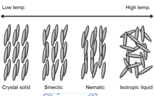
Typically, the phases of LC can be classified into crystal solid, smectic, nematic, and isotropic liquid under different range of temperature, as shown in Figure 2-1. At low temperature, the LC is in crystal solid state and the molecules have very high order in positions and orientations. When the temperature is increased, the state becomes to smectic phase. In this state, not only the orientations but also the positions of LCs become more random, and form a layered structure. Generally, LC in smectic phase higher viscosity and slower response time to applied electric field compared to nematic phase. When the temperature further increased, LC
is transformed to nematic phase, which is the most common state. In this phase, the LC molecules have partial orientation and aligned in one-dimension space. Nematic phase has the advantage of low viscosity and faster response time. Therefore, it is wildly employed in many applications, such as LCD and other kind of displays. In this thesis, we also focus on this advantage, and utilized it for our research. At high temperature, the LC material becomes isotropic phase, which the orientations and positions of molecules are totally random. In this state, LC has no birefringence.
Figure 2-1 The phases of LCs under different range of temperature
2.2 Energies in LC Cells
Direction of LCs is uniform in the LC cell when there is no external energy or confinement. If there is applied energy or other limited conditions, the spatial directions of LCs will be re-orientated, and this change was named the deformation. To investigate and calculate the change of directors, continuum theory is well-used in calculating the equilibrium of energies in LC cells. Generally, these energies are considered including free energy density on uniform
state ( ), elastic energy ( ), electric or magnetic energy ( ), anchoring effect ( ),
and so on, as shown as Equation (2-1).
19 Elastic Energy
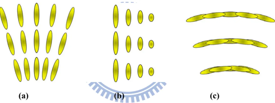
In the nematic phase, there are three possible forms of deformation as shown in Figure 2-2. These forms were called splay, twist, and bend representing each specific variation of LC directors, , which indicates the directions of LC molecules, as shown in Figure 2-3. The general equation used to describe the energy stored by the three forms of deformations is
1 2 ∙ 1 2 ∙ 1 2 (2-2)
Each term in the left side indicates the deformation energy of the three forms. This equation is
usually referred to as the Ossen-frank energy, and , , and represent the splay
twist, and bend elastic constant of LC material respectively.
(a) (b) (c)
Figure 2-2 The three possible forms of deformation, (a) splay, (b) twist, and (c) bend, of nematic LCs.
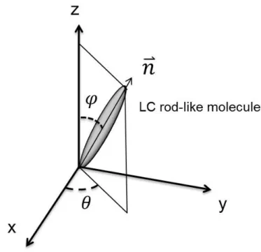
Figure 2-3 LC directors, , which indicates the directions of LC molecules in Cartesian
coordinate Electric Field
Electric field is considered to re-orientate LC directors because it induces polarization. While
the permittivity of LC molecule in the direction parallel to , ∥, is different from that of
perpendicular direction, , the polarization can be changed by applying different field. By
decomposing the field into two perpendicular directions along and perpendicular to , as shown in Figure 2-4. The induced polarization can be analyzed by
∥ ∙ (2-3)
Thus, the electric energy of LC is derived as following:
1 2 ∙ 1 2 ∥ ∙ 1 2 (2-4)
21
Figure 2-4 The field was decomposed into two perpendicular directions along and perpendicular to .
Anchoring Effect
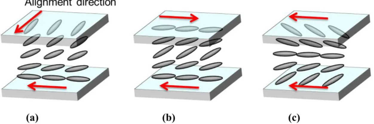
In reality, to fabricate LC cells, the boundary forces of the substrates affect the equilibrium state. This force is usually achieved by coating an alignment layer on the substrates, and the directions of the layers can determine the initially configuration of LC directors. By arranging the directions of upper and lower substrates, stabilized LC profiles can be generated in specific types. Three of the common alignment methods are shown in Figure 2-5, the perpendicular, anti-parallel, and parallel alignments. Each of them is well-used for producing twist-nematic cell (TN), electrically controlled birefringence (ECB), and pi-cells, respectively. In the applications of LC lenses, ECB mode is wildly used for simplifying the control and structures. The force describing the anchoring effect can be expressed by Rapini-Papoular approach as following: (2-5) where 1 2 (2-6) 1 2 (2-7)
anchoring force of two components, , and respectively. and are the constant which are determined by interaction between the alignment layer and the LC molecules.
and are the angles at which the interaction has minimum energy.
(a) (b) (c)
Figure 2-5 Three of the common alignment methods, (a)perpendicular, (b)anti-parallel, and (c)parallel alignments for LC cells.
2.3 Optical Principle of LC Lenses
LC is a material exhibiting birefringence. This property causes the incident light with different polarizations meet different refractive index. For analyzing the distribution of index, the light can be decomposed into two eigen-polarizations, one of which is parallel to the optical axis of the material and the other one is perpendicular to the plane of optical axis. The parallel one which is named ordinary light sees all the same index no matter how the included angle between the incident light and the optical axis, as shown in Figure 2-6. On the other hand, the polarization which is perpendicular to the plane of optical axis, named extraordinary light, sees the refractive index which is direction dependent. Although, the index would be varied by the included angles between the incident light and the optical axis, the effective index can be calculated by Equation (2-8).
(2-8)
23
Figure 2-6 The ordinary and extraordinary lights travelling in the LC material and extraordinary lights see the different indies which are dependent to the included angles between the incident light and the optical axis of LC molecules.
LC lenses, as shown in Figure 2-7, employ the gradient electric field to control the LC layers. The distribution of the field is controlled by the applied voltages and generates phase retardation which is approximate to that of lenses to converge or diverge the incident extraordinary light. The schematic is shown in Figure 2-8. r, d, and f respectively represent the radius of lens aperture, thickness of LC layer, and the effective focal length. To derive the relation of these parameters, optical path length (OPL) of wavefront is used to explain. As shown in Figure 2-8, the LC layer of an LC lens can be considered as a GRIN Lens [61], thus the refractive index is a function of position . To simulate the focusing of the lens, we assume the rays of a plane wave passing the lens and arriving at point E have the same OPL. Therefore, the optical path difference (OPD) between ABE and CDE should be zero.
∙ ∙ (2-9)
where S , and S are the OPL of ray AB and CD respectively, and n is the refractive
index in air. Generally, the lens power of LC lenses is relatively small, thus the refraction in the LC cell can be ignored. Therefore, Equation (2-9) is approximate as
S ∙ ⇒ ∙ ∙ ⇒ ∆ ∙ ≅ ∙ 2 ⇒ ∆ ∙ ≅ ∙ 2 ⇒ ≅ ∙ 2∆ ∙ (2-10)
where ∆ indicate the difference of refractive index between border and center. By
substituting r, d, and f for the length , , and DE, Equation (2-10) can be rewrite as
≅ ∙
2∆ ∙ (2-11)
In Equation (2-11), we have assumed the straight propagating of rays in LC layer, and the
effective index, and at the border and center of the lens. To obtain a unique focal
length, f, from the whole lens aperture, the distribution of ∆ is
∆ ≅ ∙
2 ∙ ∙ (2-12)
which is a parabolic form of variable, .
Figure 2-7 The wavefront focusing of LC lens.
25
Figure 2-8 The diagram of LC lens considered as a GRIN lens for analyzing the focusing.
Chapter 3.
Multi-electrode Driven LC Lens
To have a tunable lens, the LC lenses were expected to produce superior focusing at each focal length, which can yield similar image quality for focusing objects at different position. Therefore, a well control for the electric field is required. In this chapter, we proposed Multi-electrode Driven LC Lens to have such high control freedom yielding superior focusing for each focal length by operating different sets of driving voltages.
3.1 Introduction
As mentioned in section 1.4.1.3, to achieve LC lenses exhibiting highly focusing ability, the spot size of PSF should be minimized for each focal length. However, the conventional structures with low control freedom, as introduced, are hard to significantly yield desired electrical field to control the LC orientation for wide range of focusing. Figure 3-1 shows a focusing example of the homogeneous LC lens with internal electrodes. When the higher driving voltage was applied, the higher focusing light intensity can be detected at focal length, 4cm, and the full width at half maximum (FWHM) of the spot size is 65um. When the driving voltage was decreased, however, the maximum light intensity was detected at focal length, 10cm, with a different beam profile from that of 4cm, whose FWHM increased to 121um. If we employed these results for AF, the image performances are different for objects at different
distance. To finely control the phase retardation of LC layer, Multi-electrically Driven
Liquid Crystal Lens (MeDLC Lens) was propose. MeDLC Lens utilized a large number of electrodes to significantly control the electrical field on LC layer. By optimizing the sets of driving voltages for different focal length, a wide range of superior focusing was yielded.
27
Figure 3-1 The focusing profile of the homogeneous LC lens with different focal length, 4cm and 10cm. The focusing profiles are different.
3.2 Multi-electrically Driven Liquid Crystal Lens (MeDLC Lens)
3.2.1 MeDLC Lens
The main concept of MeD-LC Lens is to utilize a large number of electrodes to finely control LC orientation, as the structure shown in Figure 3-2. To generate a smooth electrical field in LC layer, multi-electrode were constructed above a high K material (i.e. the glass). The number of electrodes and width of electrodes and slits, WE and WS, were designed for optimized the phase retardation by different aperture size, LC cell gap, and thickness of glass for different applications. By arrangement of driving voltages for each electrode, the phase retardation over the LC layer was optimized for particular focal length. Typically, the arrangement of driving voltages for MeD-LC Lens was correlated to the LC orientation. For a convex lens application, the driving voltages were higher at the marginal electrodes and decreased to the lowest voltage in the central region.
Figure 3-2 MeD-LC Lens with large number of electrodes. MeD-LC Lens utilized the arrangements of driving voltages to finely control the LC orientation, and yielded a wide range of superior focusing
3.2.2 Optimization
To optimize the number of electrodes, errors of phase retardation generated by MeD-LC Lens was quantified. The difference of reflective index of LC lenses is shown following:
∆
2 ∙ ∙ (3-1)
where Δnl donates the average difference of reflective index between border and center of the
lens, r, f(r), and d represent the aperture radius, focal length, and LC cell gap respectively. For
an ideal case, a unique focal length for all lens apertures, the distribution of Δnl is a parabolic
curve and was used for analysis of phase retardation. As the phase retardation of MeD-LC Lens could be approximated to that of ideal one, which indicated MeD-LC Lens generates phase retardation with lower optical aberration and approaches to the lens with approximate unique focal length. So the optimization of MeD-LC Lens was focused on the design of the size of electrodes to match the ideal parabolic curve. To simplify the optimization, the ratio of WE to WS (WE/WS) was fixed to 1 for 1.5mm lens aperture. The LC cell gap and thickness of the glass were designed to 60um and 700um. LC material was chosen as Merck nematic LC (E7), which the intrinsic difference of reflective index between ordinary and extraordinary, Δn,
29
approximate 3.5cm. As the number of electrodes increased, the curve of Δnl generated by
MeD-LC Lens approached to that of ideal one. In conventional LC lens design, the large marginal electrodes usually yielded flat electrical field in the border, and cannot generate lenses with full aperture size for lens array. On the other hand, MeD-LC Lens utilized the finer electrodes to yield the phase retardation which was much close to ideal parabolic curve and with full designed aperture size (1.5mm).
A merit function defined as following:
∑ ∆ ∆ (3-2)
was used to quantify the errors between ideal distribution ofΔnl and that generated by
MeD-LC Lens, where Δni and ΔnMeD-LC represent Δnl of ideal lens and MeD-LC Lens
respectively. Through the result, as illustrated in Figure 3-4, the larger number of electrodes yielded smaller E-value, which means the curves was more approximate to the ideal parabolic one under electrical field of finely control. As the number of electrodes exceeded 9, E started to be saturate. In our study, 9 electrodes for MeD-LC Lens with 1.5mm aperture size would be a balance design.
Figure 3-3 The profile of Δnl generated by MeD-LC Lens and an ideal lens for around
3.5cm focal length. The ideal lens represented by a parabolic curve is compared with that of MeD-LC, presenting a deviation from the ideal case.
Figure 3-4 The quantified errors, E, representing the deviation of the results of MeD-LC
1.5 1.7 1.9 2.1 2.3 2.5 2.7 2.9 3.1 3.3 5 6 7 8 9 10 11 12 13 14 15 16 The Number of Electrodes E(%)
31
3.3 Experimental Results
Cylindrical MeD-LC Lens with 9-electrode and WE/WS =1 for 1.5mm aperture size was investigated. For convex lens applications, the driving voltages of each electrode, as shown in Figure 3-5, were optimized for different focal length according to the focusing profile. The result showed a symmetrical arrangement. Each driving voltage was adjusted for particular focal length. In the convex MeD-LC Lens, marginal driving voltages are higher than central voltages to form convex-like phase retardation. As the total energy increased, the focal length was shortened. Figure 3-6 (a) and (b) illustrates the experimental setup and the comparison performed by the structures with external, internal electrodes mentioned above, and MeD-LC Lens. All of the structures with 60um LC cell gap, 1.5 mm aperture size and the same substrate were illuminated by 632.8nm Hi-Ne LASER and investigated the optimized focusing profile for focal length of 4cm, 7cm, and 10cm. The focusing profile was measured by GENTEC Beamage Series CCD sensor placed in front of the LC lenses by a distance of focal length. Corresponding cross-section (bottom right) and FWHM (bottom left) of the focusing profile are shown as well. For two of the conventional LC lenses, although the external structure generated acceptable focusing at focal length from 7cm to 10cm, the 4cm showed a broken result in beam profile. On the other hand, internal structure yielded adequate results from 4cm to 7cm, but the poor focusing at 10cm which the FWHM was much increased also indicated the limitation of low freedom of control. Comparing to the results, MeD-LC Lens yielded a wide range of superior focusing at all of 4cm, 7cm, and 10cm focal length that FWHM of focusing profile was maintained narrower.
Figure 3-5 The optimized driving voltages for 9-electrode MeD-LC Lens in convex applications. The symmetrical arrangement of each driving voltage was adjusted for particular focal length. In convex MeD-LC Lens, marginal voltages are higher than central voltages to form convex-like phase retardation.
0 5 10 15 20 25 30 35 v5 v4 v3 v2 v1 v2 v3 v4 v5 f=4cm f=6cm f=8cm f=10cm f=12cm
# of Electrode
Driving
Voltage
(Vrms)
33 (a)
(b)
Figure 3-6(a) Cylindrical MeDLC Lens measured by CCD sensor at a distance of corresponding focal length (EF), and (b) the focusing profile were compared with two conventional LC lens. As the results shows, two conventional LC lenses only yielded a particular range of focusing. On the other hand, the multi-electrode of MeDLC Lens served the LC layer optimized phase retardation for each focal length and a wide range of focusing.
In our experiments, MeDLC Lens provided a smooth variance in focal length and maintained superior focusing profile. By the high freedom of multi-electrically driven, electrical field was significantly modified for different focal length from 3.5cm to infinity with 1.5mm aperture size and 60um LC cell gap. In the comparison, conventional LC lens with low control freedom only yielded focusing in a particular and narrow range. This phenomenon limits the applications for tunable lenses. MeDLC Lens provided stable performance in focusing for a wide range. This benefit can increase the feasibility for applications and achieve a highly tunable lens.
3.4 Discussion - Grating Structure of MeD-LC Lens
The electrodes of MeD-LC Lens, as shown in and the results are shown in Figure 3-2, generated obvious side lobes due to the particularly periodic grating structure. The side lobes may suppress image quality and increase the cross-talk effect. To reduce the side lobes, coating with material having high transmittance and approximate reflective index to ITO can effectively achieve. In our study, PMMA was utilized whose transmittance is larger than 90% with around 1.5 reflective index (nPMMA = 1.5) for visible light. The result is illustrated in Figure 3-7. MeD-LC Lens coating with PMMA showed a suppression of intensity in the side lobes. Although this phenomenon cannot be totally eliminated due to mismatch of reflective index, through the coating method, this issue was much reduced.
Besides, different width of the control electrodes also yields different optical properties. For example, thinner width of the electrode at the border can further finely control the LC orientations, as Figure 3-8 shows. However, the thinner area of the electrode requires higher driving voltage to maintain the same electric energy, which may much increase the driving voltage.
35
(a)
(b)
Figure 3-7(a) The focusing profile of MeD-LC Lens without coating PMMA and (b) coating with PMMA for suppressing the intensity of side lobes. The large side lobes of focusing profile due to the grating structure of MeD-LC raised undesired cross-talk effect. The coating material with approximate reflective index can effectively reduce the side lobes. 0 0.1 0.2 0.3 0.4 0.5 0.6 0.7 0.8 0.9 1 0 465 930 1395 1860 2325 2790 3255 3720 4185 Without Coating Position (um) Normalized Intensity 0 0.1 0.2 0.3 0.4 0.5 0.6 0.7 0.8 0.9 1 0 465 930 1395 1860 2325 2790 3255 3720 4185 Coating with PMMA Position (um) Normalized Intensity
Figure 3-8 MeDLC lens with different width of electrodes to further finely control the LC orientations.
3.5 Conclusion
Multi-electrically Driven Liquid Crystal Lens (MeDLC Lens) was proposed to realize a highly tunable LC lens with wide range of superior focusing. Through high freedom of multi-electrically control, the phase retardation of LC layer was significantly optimized for different focal length. In the comparison, two of general homogeneous LC lenses with external and internal electrodes were investigated. The results showed conventional LC lenses with small number of driving electrodes limit the focusing range, and only can be apply to particular focal length for acceptable focusing performance. For cylindrical MeDCL Lens with 60um LC cell gap and 1.5mm aperture size, the focusing was tunable from 3.5cm to infinity. Furthermore, corresponding FWHM of focusing profile was maintained narrower. These results indicated MeDLC Lens increase the feasibility for tunable lenses. A smooth variance in focal length and stable focusing performance in wide range were also achieved.
37
Chapter 4.
Gradient Driven Liquid Crystal Lens Exhibiting
Ultra-low Operating Voltages
So far, although we applied the structure of MeDLC lens to improve the optical properties for each focal length, we can find the driving voltage of MeDLC lens is still high (~30Vrms). Obviously, it is not only means the results are still unfeasible for general applications but also indicate the structures of LC lenses should be intrinsically innovated. In this chapter, a novel structure named Gradient Driven LC lens (GD-LC lens) was proposed. This structure intrinsically reduced the requirement for driving voltage down to few voltages. Combining with the concept of multi-control of MeDLC lens, GD-LC lens not only can be driven by operating voltage but also the driving frequency.
4.1 Introduction
Before getting into GD-LC lens, we have to discuss why the conventional structures of LC lenses usually require high driving voltage and long focusing time. Figure 4-1 (a-d) shows four kinds of homogeneous LC lenses including internal and external electrodes with single control and multi-control. Each of them was simulated the distribution of electric field inside the LC cells, as the green line shows the equal potentials. For the first structure, two internal electrodes (Figure 4-1 (a)), as the driving voltage was applied, we can find the gradient variation of electric field was yielded. This kind of electric field can be used to generate a lens profiled of phase retardation in the aperture of the electrodes. However, ratio of the potential really applied to the LC cell to generate the LC effect was low (around 10% as indicated in the figure), which means as we applied 30Vrms to the electrodes, only around 3Vrms was used. In fact, the most of the electric field leaked outside of the LC cell. On the other hand, the structure with external electrodes, as shown in Figure 4-1 (b), although the insertion of high K
material (i.e. the glass) can smooth electric field communicated to the LC layer, the ratio of the potential really applied to the LC cell was low as well. Besides, the potential difference between the border and center was small. For the structure of MeDLC lens (Figure 4-1(c)), as discussed in Chapter 3, we can notice MeDLC lens has higher ability to control the electric field communicated to the LC layer than that of structure with only two electrodes, but it still had the drawback of low efficiency. Only around 10% voltage difference was really applied to the LC cell. Therefore, the driving voltage was required very high. The last structure, internal multi-electrode, as shown in Figure 4-1 (d), simulated discrete electric field in the LC cell due to the non-uniform arrangement of electrodes. This kind of electric field cannot generate lens profile which requires a smooth variation in the orientation of LC directors. Nevertheless, the potential applied to the LC cell can be totally fed to deform the LC molecules.
To summarize the above discussion, our previous simulation work indicated the configuration with internal continuous-distributed electrode has the ability to achieve gradient electrical field and maintain the energy inside the LC layer. These two features not only yielded the gradient phase retardation, but also sufficiently employed the applied energy. Figure 4-2 shows a structure for achieving these. Inside the LC layer, the applied energy is conserved by the covered continuous-distributed electrode, as the equal-potential lines show, which is distinguished from the conventional structures leaking out the electrical field. The generated gradient electrical field, as well, yielded gradient distribution of LC molecule to form lens-like phase retardation. Thus, the applying voltage can be reduced which also implied the focusing time can be improved.
39 (a)
(b)
(c)
(d)
Figure 4-1 The simulations of electric field for four kinds of homogeneous LC lenses including (a) internal single control, (b) external signal control, (c) external multi-control, and (d) internal multi-controls.