行政院國家科學委員會補助專題研究計畫成果報告
用動態勁性法於正齒輪系的動態分析與量測 (3/3)
A Dynamic Stiffness Appr oach to Dynamic Analysis
and Measur ement for Spur Gear Tr ains (3/3)
計畫類別:□個別型計畫 □整合型計畫
計畫編號:NSC 90-2212-E-009-053
執行期間: 90 年 08 月 01 日起至民國 91 年 07 月 31
計畫主持人:呂宗熙
共同主持人:
計畫參與人員: 黃國饒、簡士浤
本成果報告包括以下應繳交之附件:
□赴國外出差或研習心得報告一份
□赴大陸地區出差或研習心得報告一份
□出席國際學術會議心得報告及發表之論文各一份
□國際合作研究計畫國外研究報告書一份
執行單位:國立交通大學
中
華
民
國 91 年 8 月 1 日
行政院國家科學委員會專題研究計畫成果報告
用動態勁性法於正齒輪系的動態分析與量測 (3/3)
A Dynamic Stiffness Approach to Dynamic Analysis and Measurement for Spur Gear Trains (3/3)
國科會計畫編號: NSC 90-2212-E-009-053 執行期限:90年8月1日至91年7月31日 計劃主持人:呂宗熙 [email protected] 新竹市國立交通大學機械系 Abstr act
This study presents an approach to analyze dynamics of spur gear systems using a dynamic stiffness method. Calculated and measured tip displacements and fillet strains of gear pairs are compared. Besides, a fillet strain of a two-stage gear reducer is also measured. Additionally, influence of gear design parameters is examined. the effect of gross motion on gear dynamics is also investigated. Finally, fillet strains of a gear pair are calculated using a multiple tooth-pair model to directly account for the condition of multiple tooth pairs in contact.
Keywords: Gear; Dynamic stiffness method; Correction factor, Gross motion, dynamics
1. Intr oduction
Prediction of vibration and dynamic loading become a major consideration in gear design. Kahraman and Blankenship [1] investigated the effect of contact ratio on spur gear dynamics by measuring the dynamic transmission error. Vedmar and Henriksson [2] took into account off line-of-action and nonlinear wheel stiffness using the finite element method. Discrete mass-spring models were commonly utilized for dynamic analysis of the gear systems. Continuous models can incorporate the time varying stiffness of gear systems intrinsically. However, few works on gear dynamics using continuous models have been reported [3, 4]. A dynamic stiffness method has been used in vibration analysis of beam structures [5, 6]. The present work uses the dynamic stiffness method to analyze dynamics of spur gear systems taking into account time-varying stiffness and mass matrices. Tip displacements and fillet strains of the gear systems are calculated. Experimental results serve to verify the proposed model. Furthermore,
this study also examines gear dynamic response due to changes of design parameters. Influences of gross motion effect on gear dynamics are also investigated. Finally, fillet strains of a gear pair are calculated using a multiple tooth-pair model to directly account for the condition of multiple tooth pairs in contact.
2. Dynamic stiffness of gear s
Fig. 1 depicts a spur gear pair.
Gears are
modeled with nonuniform Timoshenko
beams.
Polynomials are used to fit tooth profiles to facilitate solving dynamic equations for beams. Each beam element profile is fitted by a quadratic polynomial. Since this study takes into account time-varying stiffness and mass matrices due to moving meshing points, the instantaneous meshing point has to be updated at calculation steps during a meshing cycle. Nine points including the instantaneous meshing point on a tooth are used to fit the profile of four nonuniform cross-section beam elements.Fig. 1 a spur gear pair.
Terms of a dynamic stiffness matrix
D
(
ω
)
for a gear pair are assembled by dynamic stiffness matrices of Timoshenko beam elements for the gears and a nonlinear stiffness [7] to account for local deformation at meshing points Firstly, using governing equations for a Timoshenko beam element with u, w, and
φ
are the longitudinal, transverse displacements,-0.06 -0.04 -0.02 0.00 0.02
Roation angle (deg)
D isp la ce m en t ( m m ) 2 N-m 3 N-m 4 N-m
and the bending slope, respectively., terms in dynamic stiffness matrix for Timoshenko beam vibration are given as [7]:
i u L Ea i d 1, ) 0 ( ) , 1 ( =− , j,i j u j L ) ( Ea ) i , ( d = ∑∞ =0 1 4 ] [ ) 0 ( ) , 2 ( 1,i 0,i L w a G k i d = −φ , i L EP i d 1, ) 0 ( ) , 3 ( =− φ ] 1 )[ 1 ( ) , 5 ( 0 , 0 , ∑ ∑ ∞ = ∞ = − − = j i j j i j w j L a G k i d φ (1) ∑∞ = = 0 , ) 1 ( ) , 6 ( j ji j L P E i d φ
where
u
j,i,w
j
,
i
, and φj,i denote the jth terms in the ith shape functions, andi
=1 to 6.E is Young’s modulus, G the shear modulus, and k the shape correction factor.
3. Excitations and r esponses
The dynamic stiffness matrix D(ω) of the
gear pair consists of the terms for the gears in Eq. (1) and nonlinear contact stiffness [8]. For vibration systems undergoing forced harmonic oscillation, the dynamic stiffness matrix
M K
D(ω)= −ω2 where K and M are stiffness and mass matrices, respectively. Natural frequencies
ω
of the gear pair are calculated by performing a bisection procedure on the dynamic stiffness matrix. From Leung’s theorem [9], the mass and stiffness matrices are derived as 2 ) ( ω ∂ ω ∂ D M=− , 2 2 ( ) ) ( ω ω ω ω ∂ ∂ − =D D K (2)A response component vector qi is defined as a component of q due to the
i
th mode with a natural frequencyω
i
. Therefore, ∑=
= N
i 1 i
q q
where N is the number of modes taken into account for a desired accuracy of the response. Using Mi and Ki with respect to the natural frequency ω obtained by Eq. (2), excitation i force
i
F, and initial conditions, the displacement i
q can be solved from
i i i i iq K q F M && + = (3)
According to the method [10, 11], the excitation force becomes o i e i F M u F = − && (4) In this study, the external force
e
F applied on
the gear pair is the driving torque. Also, for a gear pair with constant rotation speed,
o iu
M && is
the centrifugal force and the centripetal acceleration.
R u& θ&2
&o =− (5)
where θ& is the gear rotation speed and R is a position vector consisting of rotation radii from the gear center to the element nodes.
The modal response is obtained by performing the Runge-Kutta method for Eq. (3). Further, the forced responses q at nodes are obtained by superimposing all the displacement responses
i
q . Finally, based on these nodal displacements q , strains and stresses at an arbitrary point in the
tooth can be calculated.
4. Numer ical and exper imental r esults
Example 1: This example compares numerical
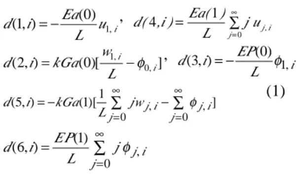
and experimental tip displacements for an MC-Nylon gear pair of two mating identical gears with module m =3 and number of teeth z= 28. The gear pair has a contact ratio 1.64. Hence, during a meshing period, the number of contact tooth pairs of the gear pair is either one or two. The tip displacements at three different torque levels of 2, 3, and 4 N-m at a speed of 300 rpm are depicted in Fig. 2. The responses show oscillation patterns. The maximum peak occurs at the instant of 8.9º, which is the first peak seen after the number of meshing tooth pairs changes from two to one. Several optical measurement methods [12, 13] have been used in measuring gear dynamic responses. An image processing method of less cost is developed to measure the tip displacements. Table 1 compares the experimental and numerical maximum tip deformations and shows they are very close.
-4000 -2000 0 2000 4000 6000 0 2 4 6 8 10 12 14 16 18
Rotation angle (deg)
M ic ro st ra in
Table 1 Experimental and numerical results of maximum tooth tip deformation at 300 rpm.
Torque (N-m) Tip deformation (mm) Experimental Numerical 2.0 0.022 0.024 3.0 0.031 0.034 4.0 0.047 0.046
Example 2: This example deals with aluminum gear pair also with two mating identical gears but with nonstandard tooth profiles. A strain gauge is also used to measure fillet strains. Gear data are same as those in the above example except that correction factors
æ1= æ2= -0.25. The numerical and experimental
fillet strains subject to 3 N-m at 2000 rpm are shown in Fig. 7, which show that all their oscillation period conform well, but the maximum of the numerical results is a little smaller.
Fig. 3. Numerical and experimental results of fillet strains by torque 3 N- m at 2000 rpm.
Example 3: The measured fillet strain of a
two-stage plastic gear reducer in Fig. 4 at 300 rpm under 3 N-m is given in Fig. 5. The result shows that the response does not appear regular vibration oscillation as obtained in the single gear pair. Gear precision, assembling error, and many components in the gear train complicate the system cause the vibration noise. The theoretic results can be further.
Fig. 4. A two-stage gear reducer.
Fig. 5. Experimental results of two-stage gear reducer.
5. Par ametr ic analysis
Dynamic performance of gear pairs can be improved by suitably adjusting correction factors, center distance, and backlash between meshing teeth. Influence of these gear parameters on the gear dynamic responses is further investigated for an aluminum gear pair consisting of two identical gears with identical correction factors, i.e. æ1= æ2= æ.
Firstly, the center distance of the
gear pair remains standard while both
correction factors for gears are varied. The
maximum microstrains of the responses for
the gear pairs are depi
cted in Table 2 which shows the gear pair with æ= -0.25 at 2000 rpm has the largest microstrain while the smallest value occurs for æ=0.0 at the 4000 rpm. The correction factor æ= -0.25 causes a largest strain. Next, depending on gear correction factors, the center distance of the gear pair will be adjusted to zero backlash. Their maximum microstrains of the responses are depicted in Table 3. The result shows that the negative sum of correction factors has a smallest fillet strain since the gear pair has a largest contact ratio.Design parameters greatly influence the dynamic response of a gear pair. Suitable correction factors can improve the gear dynamic performance but other relevant parameters like the center distance and the meshing backlash also have to be simultaneously taken into account.
Table 2. Maximum fillet microstrains of different correction factors of gear pair with standard center distance. Speed (rpm) Correction factor æ= -0.25 æ= -0.10 æ= 0.0 2000 300 208 162 3000 295 163 157 4000 292 159 131
Table 3. Maximum fillet microstrains of different correction factors of gear pair with zero backlash.
Speed (rpm) Correction factor æ= -0.25 æ= 0.0 æ= + 0.25 2000 143 162 219 3000 132 157 161 4000 127 131 152
6. Gr oss motion effect
Influences of the gross motion effect on gear -100 0 100 200 300 400 0 2 4 6 8 10 12 14 16 Rotation angle (deg)
M ic ro st ra in Experimental Numerical
-100 0 100 200 300 400 0 5 10 15 20
Rotation angle (deg)
M ic ro st ra in both driv. torque gross motion
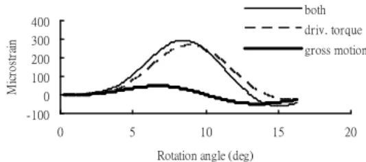
dynamics at high speeds are further examined. Firstly, the aluminum gear pair in the Example 2 is investigated The oscillate fillet strains subject to the driving torque of 3 N-m with and without the gross motion effect at 6000 rpm are depicted in Fig. 6. Further, the maxima and changes of the fillet strains at those operation conditions are depicted in Table 4. The maximum fillet strains due to including the gross motion effect increase 1.4 percent from 291 to 295 for 3000 rpm, 4.2 percent for 4000 rpm, and 7.5 percent for 6000 rpm, respectively. The effect of gross motion on gear dynamics becomes more significant as the rotation speed increases. In this example, when the speed is higher than 6000 rpm the gross motion effect becomes significant and should not be ignored. Table 4 also depicts that the strain maxima solely caused by the driving torque become smaller when the speed goes up. During a teeth meshing period, response times for the fillet strains to achieve the maxima at high or low speeds are same. When the gear pair rotates at higher speed, the meshing point, which the fillet strain achieves its maximum, is closer to the tooth root than it at lower speed.
Fig. 6. Fillet strains of an gear pair including the gross motion effect or not at speeds of 6000 rpm.
Table 4. Calculated maximum fillet strains of an aluminum gear pair with, without, and only the gross motion effect and strain increase percentage due to gross motion.
Speed (rpm)
2000 3000 4000 6000
Without gross motion 288 291 289 264 With gross motion 286 295 301 294 Only gross motion 7 16 26 49 Increasing percentage % -0.7 1.4 4.2 7.5
7. Multiple tooth-pair model
Finally, a model of the multiple tooth-pair as shown in Fig. 8 is used to directly account for the condition of the multi tooth pairs in contact. Using the multi tooth-pair model, the fillet strain of the aluminum gear pair in the Example 2 is
calculated. In contrast to the single tooth pair model by equally sharing the driving torque when the number of tooth-pairs in contact is multiple, the multiple incorporates the contact tooth pair number by directly assembling all to the system dynamic stiffness matrix D(ω) of the gear pairs. Fig. 8 compares the fillet strains respectively by using the multiple tooth-pair model, single tooth pair model, and experiment under 3 N-m at 2000 rpm. All the measured and calculated results conform well. The amplitude of fillet oscillation using the multiple tooth-pair model is a little larger than the result using the single model. During the period of the single tooth pair in contact between 3.4º and 12.8º, the strains of the gear pairs using both models are very close. However, the oscillation period for the multiple model is short than that of the single model since the multiple model has higher natural frequency for its higher stiffness due to multi meshing tooth pairs. Besides, the amplitude using the multiple tooth-pair model is closer to that using the experimental result, while the oscillation periods using the single gear pair model and the experiment conform better than the multiple’s. However, both models are suitable for gear dynamic analysis.
Fig. 7. A gear pair of multi tooth-pair model.
-200 0 200 400
0 5 10 15
Rotation angle (deg)
M ic ro st ra in Multi Single Experimental
Fig. 8. Fillet strains of an aluminum gear pair of multi tooth-pair model, single tooth-pair model, and experiment at 2000 rpm.
8. Conclusions
A dynamic stiffness method based on equations of motion for a Timoshenko beam model has been developed to simulate spur gearing dynamics during meshing. The maximum tip displacements and fillet strains occur at instants either the number of tooth pairs in contact is the least or contact nearest tooth tips of driven gears. Experimental results
verified the numerical results. Besides, a fillet strain of a two-stage gear reducer is also measured. This work has further investigated the influence of design parameters on gear dynamic response. It is observed that design parameters greatly influence the dynamic response of a gear pair. Besides, the gross motion effect on gear dynamics has also been investigated. With increasing gear rotation speed, the strain caused by the gross motion effect becomes more significant and should not be ignored. Finally, the model of the multi tooth-pair to directly simulate the multi tooth-pair meshing condition is developed. Fillet strains of using the models of the single tooth-pair and the multiple tooth-pair are close.
Refer ences
[1] A. Kahraman and G. W. Blankenship, Effect of involute contact ratio on spur gear dynamics, ASME Journal of Mechanical Design 121(2) (1999) 112-118.
[2] L. Vedmar and B. Henriksson, A general approach for determining dynamic forces in spur gears, ASME Journal of Mechanical Design, 120(4) (1998) 593-598.
[3] F. M. L. Amirouche, G. C. Tajiri, and M. J. Valco, Mathematical model of a time and position variant external load on a gear tooth using the modified Timoshenko beam equation, International Journal for Numerical Methods in Engineering 39(12) (1995) 2073-2094.
[4] S. Vijayarangan and N. Ganesan, A study of dynamic stresses in a spur gear under a moving line load and impact load conditions by a three-dimension finite element method, Journal of Sound and Vibration 162(1) (1993) 185-189
[5] J. R. Banerjee, Dynamic stiffness formulation and free vibration analysis of centrifugally stiffened Timoshenko beams, Journal of Sound and Vibration 247(1) (2001) 97-115.
[6] M. Eisenberger, Exact static and dynamic stiffness matrices for general variable cross section members, AIAA Journal 28(6), (1990) 1105-1109
[7] K. J. Huang and T. S. Liu, Dynamic analysis of a spur gear by the dynamic stiffness method, Journal of Sound and Vibration 234(2) (2000) 311-329.
[8] R. W. Cornell, Compliance and stress sensitivity of spur gear teeth, ASME Journal
of Mechanical Design 103(2) (1981) 447-459.
[9] T. H. Richards and A. Y. T. Leung, An accurate method in structural vibrating analysis, Journal of Sound and Vibration 55(3) (1977) 363-376.
[10] T. S. Liu and J. C. Lin, Forced vibration of flexible body system: a dynamic stiffness method, ASME Journal of Vibration and Acoustics 115(4) (1993) 468-476.
[11] K. J. Huang and T. S. Liu, Dynamic analysis of rotating beams with Nonuniform cross sections using the dynamic stiffness method, ASME Journal of Vibration and Acoustics 123(2) (2001) 536-539.
[12] M. J. Wang, Photoelastic investigation on the bending stress of spur gear tooth in transmission, International Conference on Advanced Technology in Experimental Mechanics (1999) 21-24.
[13] J. F. Li, W. X. Liu, C. M. Zhu, and Z. R. Tian, Measurement of gear tooth instantaneous deformation by optical method, SPIE 2300, (1996) 117-122. 中文摘要 本研究以連體模式、應用動態勁性法分析 正齒輪系在運轉下之動態變形與應變。用非 均勻截面的提末辛科樑動態勁性矩陣模擬齒 輪、以赫茲變形模擬輪齒接觸,建立齒輪系 統動態勁性矩陣,計算齒頂變形和齒根應 變。以 CCD 照相機和應變計、分別獲得齒部 的變形與齒根部應變。實驗結果驗證理論的 正確性。並量測二階齒輪減速系之齒根部應 變。此外探討齒輪設計參數對齒輪動態之影 響。由於齒輪轉速日漸增高、本計畫亦探討 齒輪旋轉之離心力對動態之影響。最後以多 齒囓合之模式研究齒輪對、在囓合齒數變化 情況下齒輪之動態