Two-stage circular-convolution4 ike
algorithm/architecture for the discrete cosine
transform
W.-J. Duh J.-L.
W U
Indexing terms: Signal processing, Algorithms, Transforms
Abstract: Because of the great improvements in computer engineering, digital signal processing has been getting more and more important in recent years. Since discrete transformations play a significant role in digital signal processing, they have found many applications in various fields. The discrete cosine transform (DCT) is well known for its usefulness in the fields of image pro- cessing and data compression. With recent advances in the ISDN, limited communication bandwidth has become a new bottleneck, a pos- sible solution to which may be an efficient encod- ing algorithm/architecture. The paper presents a two-stage algorithm and its corresponding archi- tectures for efficient computation of a power-of- two length DCT. In this approach, the transform matrix of the DCT is decomposed into the product of two matrices, the preprocessing and the postprocessing ones. The elements in the pre- processing stage consist of 1, - 1, and 0 only; the postprocessing stage is of block diagonal form in which each block performs a circular-convolution- like (CCL) operation. Thus, both stages can be implemented efficiently either by software or hard- ware. Details of the matrix decomposition are described and several corresponding architectures are also presented.
1 Introduction
Since its introduction the discrete cosine transform (DCT) [l] has found a number of applications in image processing [2] and in speech processing [3]. It has also been shown that the DCT has a performance very close to the statistically optimal Karhunen-Ldve transform (KLT) for a large number of signal classes [4, 51. There- fore, many fast algorithms for computing the DCT have been derived. A comprehensive review of various fast DCT algorithms was given in Reference 6 and a few novel recursive DCT algorithms were presented in Refer- ences 7 and 8. Since they are mostly used in various signal-processing applications, DCT processors with real- time computation capabilities are urgently required. DCT architectures have been proposed to meet this requirement, such as the distributed arithmetics DCT of Sun er al. [SI, the concurrent DCT [lo] and the constant-rotation DCT of the authors [I 13.
Paper 7514F (E5), first received 19th December 1989 and in revised form 24th April 1990
The authors are with the Department of Computer Saence and Infor- mation Engineering, National Taiwan University, Taipei, 10764, Taiwan, Republic of China
IEE PROCEEDINGS, Vol. 137, P t . F , N o . 6, DECEMBER 1990
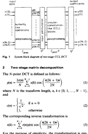
In this paper, a two-stage algorithm/architecture for computing a power-of-two length DCT is proposed. The preprocessing stage consists of values 1, - 1, and 0. The postprocessing stage is of block diagonal form with maximum block size N/2. Each block is of circular- convolution-like (CCL) form. The difference between the circular-convolution and the CCL lies in the sign of the elements. The postprocessing stage is totally parallel among blocks and can be realised by using the modified contemporary circular-convolution architecture [ 12, 131 within each block. Thus, both the pre- and postprocess- ing stages can be implemented efficiently. The system block diagram of the proposed algorithm/architecture is shown in Fig. 1.
input dato
Fig. 1 System block diagram oftwo-stage C C L D C T
2 Two-stage matrix decomposition
The N-point DCT is defined as follows:
output coefficients
at
where N is the transform length, n, k E (0, I ,
. .
., N - l},and
i f n = O (1, otherwise
The corresponding inverse transformation is
N- I
x(k) =
1
c(n)y(n) cos" = O (3)
For the purpose of simplicity, the transformation is rep- resented in matrix-vector form. The DCT transform matrix, with length N, is denoted as C,. An input column vector X = [xo, xlr
. . .
, xN-11'
is transformed tothe output vector, denoted by Y, as
where D, = ( 2 / N ) diag (c(O), c(l),
..
.,
c(N - 1)).in this paper is focussed on the transform matrix C,.
2.1 Index partitions
Consider the E T with power-of-two length only, that is N = 2", where m is a positive integer. Some definitions and lemmas for the index partition are given below.
Definition I: Z , stands for the set of integers (0, 1, .
. .
, 2" - l}, where m is a positive integer.Lemma I: The integer set Z , is the disjoint union of the subsets A i :
wherej E Z,,-,-
,
and i E (0, 1, . . . , m - l}, and A, = {0}, i.e.Y
= D,C,X (4)For the purpose. of simplicity, the algorithm discussed
A i = {2'(2j
+
1))Z" =
IJ
A i mi = O
and A i n A j =
4,
for i # j .Proof: See Appendix 8.1.
For example, when m = 4, the set Z4 can be decomposed
into A , = (1, 3, 5 , 7, 9, 11, 13, 15}, A , = ( 2 , 6, 10, 14}, A, = {4, 12}, A, = (8) and A, = (0).
Definition 2: Let g ( x ) = 2x
+
1, where x E Z,-,
and g isa mapping from Z, ~
,
to A , .Since the transform kernels of DCT are cosine functions, they possess the same symmetric properties, such as cos ( n / 2 - 0) = -cos (n/2
+
0) for 0 E CO, n / 2 ] . Using the symmetric property, a functionf(g(k), n) can be defined to explore the symmetry of the transform matrix.Definition 3:
( 5 )
where k, n, and f(k, n) E (0, 1, ..., N - 1, N}. The func- tion abs (.) denotes absolute value and the operation mod,, is similar to that of modulo 2N except that the valid range is in { - N
+
1,. . ., - 1,0, 1,..
., N}.f (k, n) = abs (kn mod,,)
The definition of f(g(k), n) is to formalise the index mapping of the DCT. We ignore the sign of the cosine functions in the transform kernels: only the absolute
values are considered. Hence, the argument k, n of func- tionf(g(k), n) denote the input and output indices, respec- tively, and the corresponding value is the angle to be computed in the transform. As indicated in definition 3, only the absolute values are involved. Thus, the sign signals are treated as additional control signals for the convolvers and are described in detail in the next Section. With the aid of the index mapping function defined in definition 3, we proceed to partition the index space to achieve higher order parallelism.
Lemma 2: For all n E A i and k E A , , the values of f(k, n) E A i .
Proof: See Appendix 8.2.
Lemma 2 explores the parallelism implied in the trans- form kernels of the DCT. That is, to compute any output value fin), only those angles in A i are required where n E A i . Since lemma 1 forms an index partition of the
index set Z, into m
+
1 subsets with maximum size N / 2 , the transform matrix C, can be decomposed into m+
1 independent submatrices which can be computed totally in parallel.2.2 Transform matrix decomposition
For simplicity, let
e,
= QCN where Q is a proper permu- tation matrix for output indices. In the following, sub- scripts are used to denote the corresponding ranks of the matrices. The matrixe,
can be factorised as follows [14]:e,
=[
' " / 2 'N/2 'kO] RN/2 - R N / 2 'k/Zwhere Iki2 denotes the opposite diagonal identity matrix. It is clear that the submatrix can be factorised recur- sively. The submatrix is left unfactorised as the maximum block of the postprocessing stage. After (log, N) - 1 iterations, the matrix is decomposed into
two stages. The preprocessing stage consists of data reversing and butterfly operations only, however the postprocessing stage is of block diagonal form. In eqn. 6, the second matrix on the right-hand side performs the
1
butterfly omrations often seen in FFT algorithms, andthe third matrix will reverse the lower half data.
for example,
e,,
becomesFor simplicity, we denote cos (8n/32) as C,. Therefore, -
CO CO CO CO CO CO CO CO CO CO CO CO CO CO CO CO
c, -c, -c,
c,
c, -c,
-e,
e,
C8-e, -e,
c,
c,
-c,
-c,
c,
c4
c,,
-c12-c4
-c12-c4
c4c,,
c4
c12-c,z
-c4
-c12-c4
c4
c12c12
-c4
c4
- c l 2-c4
c12 -cl2c4
c12-c4
c4
-c,z
-c4
c12 -c12c4
c2 c6 - c 1 4 - c 1 0 - c 2 c 2 c6 cl, c l , - c 1 4 - c 1 0 - c 6 - c Z '6 -'I4 -'IO '10 ' 2 '14 6' -'I4 -'IO '10 '2 '14 6'
-cl, -cl0
c6
- c 2 c Z - c 6 - c 1 4 - c 1 0 c6 c2 - c 6 cl, - c 1 4'10 -c2 c6 - c 6 - c 1 4 - c 1 0 -c2 - c 6 - c 1 4 c2 - c 1 0
c ,
e,
c,
c,
c,
e,, e,, e,, -e,,
-c,,
-e,, -e,
-c,
-c,
-c,
-e,
e,
c,
c,,
-cl,
-e,
c, e,
c,, -c,, -c, -c,
c,
c,, -e,,
-c,
-c,
e, -e,
c,,
-e,
-cl)
c, -e,,
c,
-c,
c,,
-e,
e,, e, -e,,
e,
-c,
c,
c,,
-e7
c3 c,, -c,
c ,
c,,
-ell
-e,
c, -c,,
-e,
c7
-cl,
-cs
c,,
c,,
e,, c,
e,
c, c,
e, -e, -e, -e,
-c, -c,
-e,, -c,,
-cl,
c,
e ,
-c,
-ell c,,
c,
e,
-c,
-e, -e,, e,, e, -e, -e,
-c,,
-e,,
c,
-cl,
-e,
e,, -e,
e,
-c,
c,
-c,,
c, e,, -c3
c,,
-e,
c,
-c,
e,, c, -c,
e,, c,
-c, -e1,
e, -e3
-cl,
c, -c,
-e1,-
(7
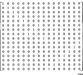
Now, if the permutation matrix
Q
is chosen to be - 1 0 0 0 0 0 0 0 0 0 0 0 0 0 0 0 0 0 0 0 0 0 0 0 1 0 0 0 0 0 0 0 0 0 0 0 1 0 0 0 0 0 0 0 0 0 0 0 0 0 1 0 0 0 0 0 0 0 0 0 1 0 0 0 0 0 0 0 0 0 0 0 0 0 0 0 0 0 0 0 0 0 0 0 0 0 1 0 0 0 0 0 0 0 0 0 0 0 0 0 0 0 0 0 0 0 0 0 0 0 1 0 0 0 0 0 0 0 0 0 0 0 1 0 0 0 0 0 0 1 0 0 0 0 0 0 0 0 0 0 0 0 0 0 0 0 0 1 0 0 0 0 0 0 0 0 0 0 0 0 0 0 0 0 0 0 0 0 0 1 0 0 0 0 0 0 0 0 0 0 0 1 0 0 0 0 0 0 0 0 0 0 0 0 0 0 0 0 0 0 0 0 0 0 0 0 0 1 0 0 0 0 0 0 0 0 0 0 0 0 0 1 0 0 0 0 0 0 0 0 0 1 0 0 0 0 0 0 0 0 ~ 0 0 0 0 0 0 0 0 0 0 0 1 0 0 0 0From eqn. 6, a recursive algorithm for computing the preprocessing stage can be derived easily. Fig. 2 shows the signal flow graph of the resultant fast algorithm of the preprocessing stage of a 16-point example, Fig.
then the preprocessing stage of a 16-point DCT can be factorised as
From lemma 2, it is clear that the input indices g(k) E
the Output indices E and the
rotation a n g I e f ( d 4 n) E A , . Thus, according to the defi- nition of f ( g ( k ) , n), a binary operator can be defined as (9)
The corresponding postprocessing matrix is of block diagonal form as shown below:
-
c o o o
0 0 0 0 0 0o c , o
0 0 0 0 0 0o o c ,
c,,o
0 0 0 0 0 0c,, -c,
0 0 0 0 0 0 0 0 0c,
c,
c,, c,,
0 0 0 0 0c,
-c1,
-c2
-c,,
0 0 0 0 0c,, -c,
c,, c,
0 0 0 0 0c,,
-c1,
c,
-c,
0 0 0 0 0 0 0 0 0c,
0 0 0 0 0 0 0 0c3
0 0 0 0 0 0 0o . c , -
0 0 0 0 0 0 0 0c5
0 0 0 0 0 0 0 0c,,
0 0 0 0 0 0 0 0c,,
0 0 0 0 0 0 0 0c 7 -
- 0 0 0 0 0 0 0 0c,,
is, with appropriate input/output permutations, each block in the postprocessing stage can be computed uti- lising the circular-convolution hardwares [12, 131.
Since A i corresponds to a block in the postprocessing stage of size 1 A i
1,
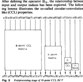
only A , , the largest block, will be dis- cussed here. Following the same strategy, other blocks can be constructed without difficulty.z (15) z.(q3) ;(?I) z(9) z(7) 2(5)z(3) z (1 z ( l L ) 2 (10) z(6)z(Z) z (IZ)z(L) z(8) z(0) Fig. 2 Preprocessing stage ofl6-point two-stage C C L D C T
0 0 0 0 0 0 0 0 0 0 0 0 0 0 0 0 0 0 0 0 0 0 0 0 0 0 0 0 0 0 0 0 0 0 0 0 0 0 0 0 0 0 0 0 0 0 0 0 0 0 0 0 0 0 0 0 c3 c5 c7 c9 c l , cl, c15 c9 c l , - cl, - c5 cl c7 ‘1.3 - c 5 c 1 3 - c l - cl, c3 - c l , c7 CIS
-c,
c3 c13 -c9 Cl C l l cl, c l , ‘9 ‘7 5‘ ‘3 ‘1 c7 ‘1 - 5‘ - ‘11 ‘15 ‘9 ‘3-cll
c3 - c l ,-cl
c13 - c S c9 cl -c9 cl, c 3 - c 7 cl, c 5 .2.3 Circular-convolution-like pOStProcessing stage Definition 4 :
B N
is a binary operator defined over the setOne way to achieve fast computations is to decompose further the submatrices in expr. 10 [8, 141. In this paper, we present another approach from the view point of architecture rather than the number of operations. That
IEE PROCEEDINGS, Vol. 137, Pt. F , No. 6 , DECEMBER 1990
A , , The definition of
B~
iswhere mod,, is defined in definition 3.
(11) @ N n = abs ( k n
After defining the operator @ N , the relationship between input and output indices has been explored. The follow- ing lemma illustrates the so-called circular-convolution- like (CCL) properties.
CCL block whose length is the size Of the block. Note that in definition 4 only the absolute values of the cosine functions are formalised, hence sign factors are excluded
&point CCL matrix
since the DCT kernels are used in the matrix and the input signals in the column vector, then summing column-wise will lead to the semisystolic array imple-
4-point matrix
Fig. 3 Postprocessing s t q p 4 1 6 - p o i n t C C L DC7
Lemma 3: G , = { A o ; generator of the group. Proof: See Appendix 8.3.
From lemma 3, the generator 3 can generate the sequence
of the cyclic group as shown in Table 1 [l5, 161. It is clear that the circular-correlation matrix is of the same form as given in Table 1 . It is well known that time- reversion of circular-correlation becomes circular- convolution. Therefore, if the output indices are permuted according to the sequence generated by 3 and input indices are permuted as time reversal of the new output orders, each block in the postprocessing stage is a
Table 1 : Operation table of a cylic group
B e a b c
is a cyclic group, and 3 is a
e e a b c
a a b c e
b b c e a
c c e a b
e denotes identity and a denotes generator
diagonal matrix with maximum block size N/2. Each block is of CCL form. The reason why we call it CCL is that the matrix is of circular-convolution form except for some sign changes. The CCL form can be formulated as follows :
N - 1
An)
=1
sg (k, n)x((n - k) mod N)h(k) (12) k = Owhere
An)
denotes the output, and x(.) and h ( . ) denote the two input sequences for convolving. The function sg(.) controls the type of convolution. When sg (.) = 1, eqn. 12 represents a circular convolution, otherwise, if sg (k, n) = sign (n - k), eqn. 12 becomes a skew circular convolution, where1, if x
>
0- 1 , i f x < O sign (x) =
The function sg (.) for CCL is defined in eqn. 14. It can be treated as the control signals of the CCL architecture
[12, 131. Note that the magnitudes of the postprocessing
functions are defined by the operator O N and the corre- sponding signs are defined by sg (.).
(14)
sg (k, n) = sign (g(k)n
+
h’ mod,,)As the transform kernels of the DCT are defined on the
4N equal divisions of the unit circle, the function sg (.) is defined according to the fundamental properties of the cosine function. The first and the fourth quadrants are positive, the others are negative.
4
Since the postprocessing stage is composed of rn
+
1 CCL submatrices, some simple architectures, such as semisystolic [12] and systolic arrays, and transversal filters [13] can be used to calculate the results. The relationship among various hardware structures and the corresponding matrix representations will be discussed in detail in this Section.4.1 Semisystolic arrays for the
CCL
matrixThe operation of the maximal CCL block of the 16-point DCT can be expressed as a matrix vector product as
Realisation considerations for the CCL matrix
I
follows:3
From the preceding section, it is clear that in the pro- posed two-stage DCT, the postprocessing stage is a block
Additional controls of the convolver clock pulse. Since the circular conv&tion operation is
commutative, interchanging the roles of input signals and DCT kernels will still result in the desired DCT coeffi- cients.
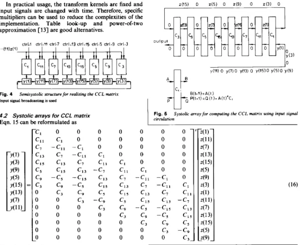
In practical usage, the transform kernels are fixed and input signals are changed with time. Therefore, specific multipliers can be used to reduce the complexities of the implementation. Table look-up and power-of-two
o u t p u t approximation [ 131 are good alternatives.
c3
GI
c5c,
b
c7 Cl, Cl c - - - - - - -0 0 0 0 0 0 0 0 0 y ~ 1 ) ctrl-1 drl-n ctrl-7 ctrl-I3 ctrl-I5 ctrl-5 drl-9 ctrl-3 -(1Vz(lFig. 4 Semisystolic structure for realising the C C L matrix
Therefore the 1-D systolic array for computing CCL can be easily derived as shown in Fig, 5 , From Fig, 5 , it is
promote the utilisation, one can interleave two input obvious that the hardware is only 50%. To
Input signal broadcasung is used
4.3 Transversal filter structures for the CCL matrix
wise instead of column-wise leads to the transversal filter From the ‘CL matrix shown in eqn. ‘’7 ‘Ow-
4 2 Systolic arrays for CCL matrix
Eqn. 15 can be reformulated as
- c 1 0 0 0 C l l Cl 0 0
c7
-cll -c,
0 c l , c 7-ell
c l c l , c l , c7 c l , ‘5 ‘15 ‘13 -‘7 ‘ 9 -‘5 -‘lS ‘13c,
c9
-c,
Cl, 0 c3c9
c5 0 0 c3 -c9 0 0 0 c3 0 0 0 0 0 0 0 0 0 0 0 0 - 0 0 0 0 U Fig. 5 rirrulafionSystolic array for computing the C C L matrix using input signal
0 0 0 0 Cl
c,
1 c7 c l , c l 5 CS c9 c3 0 0 0 0 0 0 - 0 0 0 0 0 0 0 0 0 0 0 0 Cl 0 0-cll
-c,
0 c7 - c 1 1 Cl c 1 3 c7 ‘11 c l , ‘13 -‘7 - c 5 - c 1 5 Cl, c9-c5
c,,
c3c9
cs
0c,
-c9
0 0 c3. Cl 0 0 0 0 0 0 c3 Cl 0 0 0 0 0c9
c3
-c,
0 0 0 0c,
-c9
c,
c,
0 0 0 ‘15 ‘5“3
‘3 ‘1 0 ‘13 ‘15 - c 5 ‘9 ‘3 c l ‘7 c l , - c 1 5 - c 5 c9 c 3 - c l c l , - c 7 c l , c l , cS - c 9 ‘ 3 0 ‘11 c7 c l , ‘15 c 5 c9 0 -‘ll ‘7 ‘13 c 1 5 - c S 0 0 -cll c7 c l , - c l S 0 0 0 0 c l , - c 7 c 1 3 0 0 0 0 0 C l l c7 0 0 0 0 0 0 - c 1 1 0 0 0 0 0 0 0IEE PROCEEDINGS, Vol 137, Pt F , N o 6 , DECEMBER 1990
- ~ -
twice the number of clock periods. The semisystolic array suffers from signal broadcasting and the shortcoming of the transversal filter is the requirement for global summa- tion. It is clear that for low-speed applications the systo- lic array is a good choice, yet for high-speed usages the semisystolic array and transversal filter structures are more attractive. 0 Z(l1) 0 Z(7) 0 Z(13)O z(15)O z(5) 0 z(3) 0 z(3) out 1 1 0 ~(11) 0 y(7) 0 ~ ( 1 3 ) 0 ~ ( 1 5 ) -1 0 0 0 0 0 0 0 0 0 0 0 0 0 0 0- 0 1 0 0 0 0 0 0 0 0 0 0 0 0 0 0 0 0 1 0 0 0 0 0 0 0 0 0 0 0 0 0 0 0 0 1 0 0 0 0 0 0 0 0 0 0 0 0 0 0 0 0 1 0 0 0 0 0 0 0 0 0 0 0 0 0 0 0 0 0 0 1 0 0 0 0 0 0 0 0 0 0 0 0 0 0 1 0 0 0 0 0 0 0 0 0 0 0 0 0 0 1 0 0 0 0 0 0 0 0 0 0 0 0 0 0 0 0 0 0 1 0 0 0 0 0 0 0 0 0 0 0 0 0 0 0 0 0 0 0 0 0 0 1 0 0 0 0 0 0 0 0 0 0 0 0 0 0 1 0 0 0 0 0 0 0 0 0 0 0 0 0 0 1 0 0 0 0 0 0 0 0 0 0 0 0 0 0 1 0 0 0 0 0 0 0 0 0 0 0 0 0 0 1 0 0 0 0 0 0 0 0 0 0 0 0 0 0 1 0 0 0 0 0 -0 0 0 0 0 0 0 0 0 1 0 0 0 0 0 0- U Fig. 6 Jicient circulation
Systolic arrayfor computing the C C L matrix using output coef
y(3) y ( l ) Fig. 7
circulation
Table 2 : Comparison between semisyatolic array, systolic arrav and transversal filter
Transversalfilterfor computing C C L matrix using input signal
Semisystolic Systolic Transversal filter operation mode =rial-in serial-in parallel-in
no. of clocks N 2 N - 1 N
no. of adders N N N - 1
disadvantage broadcasting low-speed global parallel-out serial-out serial-out
additional summation latches
5 16-point DCT example
From the discussions above, a two-stage decomposition of the DCT transform matrix has been derived com- pletely. The preprocessing stage consists of data permu- tations and butterfly operations; the postprocessing stage comprises several CCL blocks which can be realised by modified convolvers in parallel. To clarify the operation of the algorithm, a specific 16-point DCT example will now be given.
5.1 Two -stage decomposition
The 16-point DCT transform matrix C,, can be factor- ised into preprocessing, input permutation, postprocess- ing and output permutation stages as
- 1 0 0 0 0 0 0 0 0 0 0 0 0 0 0 0 0 0 0 0 0 0 0 0 1 0 0 0 0 0 0 0 0 0 0 0 1 0 0 0 0 0 0 0 0 0 0 0 0 0 0 0 0 0 0 0 0 0 0 0 0 0 0 1 0 0 1 0 0 0 0 0 0 0 0 0 0 0 0 0 0 0 0 0 0 0 0 0 0 0 0 0 0 1 0 0 0 0 0 0 0 0 0 1 0 0 0 0 0 0 0 0 0 0 0 0 0 0 0 0 0 0 1 0 0 0 0 0 0 1 0 0 0 0 0 0 0 0 0 0 0 0 0 0 0 0 0 0 0 0 0 0 0 0 0 0 0 0 1 0 0 0 0 0 0 1 0 0 0 0 0 0 0 0 0 0 0 0 0 0 0 0 0 0 0 1 0 0 0 0 0 0 0 0 0 1 0 0 0 0 0 0 0 0 0 0 0 0 0 0 0 0 0 0 0 0 0 0 0 1 0 0 0 0 0 0 0 0 0 0 1 0 0 0 0 0 0 0 0 0 ~ 0 0 0 0 0 0 0 0 0 0 0 0 1 0 0 0 (2
IEE PROCEEDINGS, Vol. 137, P t . F , No. 6, DECEMBER 1990 470
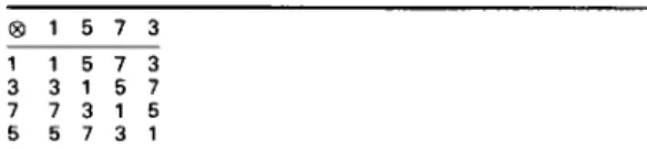
Table 3: Operation table of the 4-point CCL block showing Each block in the postprocessing stage is a circular- convolution-like (CCL) operation.
circular-convolution form
€ 3 1 5 7 3 The algorithm/architecture derived in this paper is
1 1 5 7 3 confined to the power-of-two length DCT. The upper
3 3 1 5 7 limit of the transform length is dependent upon current
7 7 3 1 5 VLSI technology. Since the implementation of the post-
5 5 7 3 1 processing stage is similar to that of a transversal filter,
the upper limit on the transform length is about twice the uppe; bound on existing FIR filter skes.
additions/subtractions. The postprocessing stage can be implemented by using existing convolvers/correlators [12, 131. Since the coefficients of the CCL matrix are fixed, table lookup and mixed power-of-two approx-
imation are Flexibility is one of the
advantages of this proposed algorithm/architecture, that
the maximum block of the 2N-point DCT and one addi- From eqn. 18, it is obvious that the computation of The preprocessing stage can be implemented by simple the 16-point DCT can
be divided into four stages as
shown in Fig. 1. Hence? the for
computing the DCT becomes:
(a) compute the simp1e preprocessing stage ‘ p e . The fast computational algorithm is illustrated in Fig. 2 and described in eqn. 9.
eqn. 21
CCL hardwares described in the Drevious Section. The
(b) permute the as given in
(cl
compute the postprocessing stage, say ‘PS~.‘, usingOf ‘P~P based On
is, if an N-point DCT is available, one needs only to add tional reversingbutterfly stage to form a 2N-point DCT, block diagram of the stage is shown’ in Fig. 3
(d) reorder the output coefficients based on Q , which is given in expr. 8.
In the 16-point DCT example, there are 8-point, 4-point, 2-point and two 1-point blocks. Each block corresponds to one of the subsets described in lemma 1. It can be easily verified that the 4-point block of the 16-point DCT is the same as that of the 8-point DCT. Therefore, each CCL block can be constructed using the same strategy. Since 3 is used to generate the output order of the 8-point CCL block, that is (3’, 3l, 3’, 33, 34, 3’, 36, 3 7 ) u m d p r ~ , a r the result is (1, 3, 9, 5, 15, 13, 7, 11). In other words, the relative output order within the block can be renumbered using g-’ (3‘ under @ 1 6 ) and becomes (0, 1, 4, 2, 7, 6, 3, 5) in this example; the corresponding input order is (1, 11, 7, 13, 15, 5, 9, 3), the time-reversal of (1, 3, 9, 5, 15, 13, 7, 11). Thus, the relative input order within the 8-point block is (0, 5, 3,6, 7,2,4, l}, the time-reversal of (0, 1,4,2, 7, 6, 3, 5). The block diagram of the example is illustrated in Fig. 8.
absolute relative relotive absolute order for order for order f o r order for permutotion permutation CCL lnput CCL Input
Fig. 8
6 Conclusions
Input orderingfor ( 0 , 5 , 3 , 6 , 7 , 2 , 4 , I }
7 References
1 AHMED, N., NATARAJAN, T., and RAO, K.R.: ‘The discrete cosine transform’, IEEE Trans., January 1974, C-25, pp. 90-93 2 JAIN, A.K.: ‘Image data compression: a review’, Proc. IEEE, 1981,
pp. 349-389
3 ZELINSKI, R., and NOLL, P.: ‘Adaptive transform coding of speech signals’, IEEE Trans., August 1977, ASP-25, pp. 299-309 4 HAMIDI, M., and PEARL, J.: ‘Comparison of the cosine and
Fourier transforms of Markov-I signals’, IEEE Trans., October 1976, ASSP-24, pp. 428429
5 CLARK, R.J.: ‘Relation between the Karhunen-Loeve and cosine
transform’, IEE Proc. F, Commun., Radar & Signal Process.. Novem- ber 1981,128, pp. 359-360
6 MAKHOUL, J.: ‘A fast cosine transform in one and two dimen- sions’, IEEE Trans., February 1980, ASSP-28, pp. 27-34
7 LEE, B.G.: ‘A new algorithm to compute the discrete wsine trans- form’, IEEE Trans., December 1984, ASP-32, (6), pp. 1243-1247 8 HOU, H.S.: ‘A fast recursive algorithm for computing the discrete
cosine transform’, IEEE Trans., October 1987, ASSP-35, pp. 1 4 5 s 1461
9 SUN, M.T., WU, L., and LIOU, M.L.: ‘A concurrent architecture for VLSl implementation of discrete cosine transform’, IEEE Trans., August 1987, CAS-34, (8). pp. 992-994
10 WU, I.-L., and DUH, W.-J.: ‘A novel concurrent architecture to implement discrete cosine transform based on index partitions’, to appear in Int. J. Electron.
11 DUH, W.-I., and WU, J.-L.: ‘A constant-rotation DCT architecture based on CORDIC techniaues’. lo avvear in In[. J. Electron.
..
12 ERSOY. 0.: ‘Semisystolic‘ array implementation of circular, skewcircular, and linear convolutions’, IEEE Trans., February 1985, C-34, (2), pp. 1-194
13 BOUSSAKTA, S., and HOLT, A.G.J.: ‘Prime-factor Hartley and Hartley-like transform calculation using transversal filter-type struc- tures’, IEE Proc. G., Circuits, Deuices & Syst., October 1989, 136, (5). pp. 269-277
14 CHEN, W.-H., HARRISON SMITH, C., and FRALICK, S.C.: ‘A fast computational algorithm for the discrete cosine transform’.
IEEE Trans., September 1977, COM-25, (9), pp. 1004-1009 15 GILBERT, J., and GILBERT, L.: ‘Elements of modern algebra’
(PWS Publishers, Boston, USA, 1984)
16 SHANKS, D.: ’Solved and unsolved problems in number theory’ (Chelsea Publishing Co., NY, 1978)
8 Appendix
8.1 Proof of lemma 1
we
complete the proof of L~~~~ 1 by using ~ ~4
l ~ ~ * ~ function,A novel, fast, parallel algorithm/architecture for comput- ing the DCT has been proposed. The derivation of the fast algorithm is based on the decomposition of the DCT transform matrix into pre- and postprocessing stages. The preprocessing stage consists of
+
1, - 1, and 0 and it (including (log, N) - 1 half data-reversing stages and d‘N log, N stages for butterflies). T h e postprocessing stage is a block-diagonal matrix with maximum block size N/2.IEE PROCEEDINGS, Vol. 137, Pt. F , N o . 6 , DECEMBER 1990
Theorem 1
can be factorised into (2 log, N) - 1 successive stages
1
&d) = N (22) where N is a positive integer and A N denotes ‘d divides N’.The index set of an N-point transformation is (0, 1, 2, . . . , N - 1). If the transform length is power-of-two, denoted
as 2", the index set can be partitioned into m
+
1 subsets, corresponding to4(d),
where d E {2', 2l, 2',..
., 2"},respectively.
8.2 Proof of lemma 2
Since n E A i and k E A , , it is obvious that gcd (n, N) =
?
for i E (0, 1, . . . , m - 1). Therefore, gcd ( f ( k , n), N) = 2', that is, the valuef(k, n) is still in the setA i .
8.3 Proof of lemma 3
First, we prove that G, = { A o ; @,} is a group. The binary operator
8,
is similar to modulo multiplication. If the number is first normalised to the set, say { - N+
1, - N+
2,. . .
, - 1, 0, 1, . . . , N - 1, N} mod 2N, then theoperation of @, is the absolute value of corresponding modulo multiplications. Since 'modulo multiplication group' is a group, it is obvious that the four properties of a group structure are satisfied in G,.
Next, we prove that 3 is a generator of group G, and 3,1Z
=
1 (under 8,)3N/4
=
N - 1 (under @,) (23)Eqn. 23 means that 3 is a generator of order N/2. The reason for using N - 1 in the second equation is that (N - 1)BAN - 1) = 1. The proof of eqn. 23 is as follows:
(a) From Euler's function, we have 34"2N'
=
l(mod 2N)3, l(mod 2N) (b) Since N = 2", we have 3"' - l(mod 2N)
=
l(under 8,)Therefore, the first of eqns. 23 is verified.
m
>
4 the proof is as follows:(c) If N = 2", for m < 4 the proof is trivial and for
3 ~ 4 = (2
+
1 y 4 =y
(y)2*
k = O +2"-1+(22"-3-2m-1)+0 + f(24m-7 - 12 23"-6+
22 22-4 - 12 2-2)+
o
+
...
+
q m o d 2""') 1 - 4 x 2"-'(mod 2"'")=
1 - 2"(mod 2"+')=
N - l(under @,) (24)Thus, G, is a cyclic group and 3 is a generator.