國
立
交
通
大
學
資訊科學與工程研究所
博
士
論
文
高可用度路由器設計與實作
Design and Implementation of High Availability Routers
研 究 生:蔡嘉泰
指導教授:簡榮宏 博士
高可用度路由器設計與實作
Design and Implementation of High Availability Routers
研 究 生:蔡嘉泰 Student:Chia-Tai Tsai
指導教授:簡榮宏博士 Advisor:Dr. Rong-Hong Jan
國 立 交 通 大 學
資 訊 科 學 與 工 程 研 究 所
博 士 論 文
A Dissertation
Submitted to Department of Computer Science and Engineering College of Computer Science
National Chiao Tung University in partial Fulfillment of the Requirements
for the Degree of Doctor of Philosophy
in
Computer Science June 2011
Hsinchu, Taiwan, Republic of China
高 可 用 度 路 由 器 設 計 與 實 作
研究生:蔡嘉泰
指導教授:簡榮宏 博士
國立交通大學 資訊科學與工程研究所
摘要
隨著網路技術的進步,人們對於網路的依賴程度也與日俱增,對網路服務提 供業者來說,如何提供一個具有高可用度的網路環境,讓使用者在進行網路存取 時不會感覺有網路中斷的情形發生,是一個很重要並且亟待解決的問題。在本論 文中,我們利用連續時間馬可夫鏈推導得到一個可用度方程式,根據此方程式, 當路由器要達到電信服務等級時,網路服務提供業者只需要提供主要路由器個數 (M)、路由器錯誤率(λ)、路由器修復率(μ)以及路由器錯誤偵測與回復率(δ)這四個 參數,本方程式就可以計算並且告知需要配置的備用路由器數量(N)。根據數值 分析的結果,我們發現錯誤偵測與回復率是用來減少建置備用路由器數量最主要 的參數,當錯誤偵測與回復率愈大,備用路由器的需求數量將會減少。 當備用路由器接手封包轉送的工作時,備用路由器會重新與鄰居路由器進行 網路連結資訊交換,用以重新建立網路拓樸表,此一動作將會造成封包轉送服務中斷。為了能夠減少網路服務中斷的時間,使得錯誤偵測與回復率能夠增加,我 們利用了完整狀態回復(Stateful backup)技術,主要的技術為,當主要路由器在運 作時,就會將其網路連結狀態資料庫同步至備用路由器,如此,當備用路由器進 行接手封包轉送工作時,備用路由器就可以根據先前收到的網路連結資料庫立刻 建立網路拓樸,並且得到路由路徑表,此時,備用路由器便可以立刻上線運作, 而不需要再向其他鄰居路由器索取網路連結資料,如此將可以有效地減少備用路 由器接手封包轉送的中斷時間。 為了能夠讓主要路由器同步網路連結資料庫至備用路由器,我們參考並修改 OpenAIS 系統,提出了一套高可用度管理中介軟體(HAM middleware),此中介軟 體可以有效地減少備用路由器接手封包轉送時的網路中斷時間,以達到增加錯誤 偵測與回復率之目的。 我們將此高可靠度管理中介軟體安裝於個人電腦(PC)的機器上,並實際進行 數值量測,以OSPF 為例,根據實驗結果得知,當備用路由器進行換手時,其網 路中斷時間將可以比Cisco-ASR 1000、Juniper MX 系列路由器與 VRRP 路由器 減少約6%、37.3%與 98.6%。 此外,我們也將此高可用度管理中介軟體安裝於ATCA 的機器上,ATCA 是 一個可以提供工業標準模組化架構的平台,可以提供我們一個高效能、靈活調整 與可靠的路由器設計。假設路由器的錯誤率與修復率分別為7 年與 4 小時,當發 生軟體類型的錯誤時,其備用路由器接手封包轉送工作的網路中斷時間為 217 ms,而當發生硬體類型的錯誤時,其中斷時間為 1066 ms。也就是說,架設於 ATCA 的高可用度路由器的可用度為 99.99999905%與 99.99999867%,皆能夠達 到電信等級可用度的標準。
根據以上我們可以得知,我們所提的高可用度路由器相較於商用的路由器而 言,因為我們所提的路由器是架構於一個開放式標準的規格,所以花費會較少將 更具有成本效益,且其備援方式可以根據網路架設與使用狀況更靈活地與有效地 進行調整。
Design and Implementation of High
Availability Routers
Student: Chia-Tai Tsai Advisor: Rong-Hong Jan
Department of Computer Science and Engineering National Chiao Tung University
Abstract
How to optimally allocate redundant routers for high availability (HA) networks is a crucial task. In this dissertation, a 5-tuple availability function, A(M, N, λ, μ, δ), is proposed to determine the minimum required number of standby routers to meet the desired availability (ρ) of an HA router, where M and N are the numbers of active routers and standby routers, respectively, and λ, μ, and δ are a single router’s failure rate, repair rate, and failure detection and recovery rate, respectively. We have derived the availability function, and analytical results show that the failure detection and recovery rate (δ) is a key parameter for reducing the minimum required number of standby routers of an HA router. Thus, we also propose a High Availability Management (HAM) middleware, which was designed based on an open architecture
specification, called OpenAIS, to achieve the goal of reducing takeover delay (1/δ) by
stateful backup. We have implemented an HA Open Shortest Path First (HA-OSPF)
router, which consists of two active routers and one standby router, to illustrate the proposed HA router. Experimental results show that the takeover delays of the proposed HA-OSPF router were reduced by 6%, 37.3%, and 98.6% compared to those of the industry standard approaches, the Cisco-ASR 1000 series router, the Juniper MX series router, and the VRRP (Virtual Router Redundancy Protocol) router, respectively. In addition, we have also implemented the HA-OSPF router on an ATCA (Advanced Telecom Computing Architecture) platform, which can provide an industrial standardized modular architecture for an efficient, flexible, and reliable router design. Based on our ATCA-based platform with 1/δ = 217 ms for a software failure and 1/δ = 1066 ms for a hardware failure, along with the router module data, 1/λ = 7 years and 1/μ = 4 hours, obtained from Cisco, the availabilities of the proposed ATCA-based HA-OSPF router are 99.99999905% for a software failure and 99.99999867% for a hardware failure. Therefore, the experimental results have shown that both our proposed ATCA-based and PC-based HA-OSPF routers can easily meet the requirement of carrier-grade availabilities with five-nine. In addition, in contract to the industry routers, the proposed HA router, which was designed based on an open architecture specification, is more cost-effective, and its redundancy model can be more flexibly adjusted.
誌謝
首先感謝指導教授簡榮宏博士歷年來的諄諄教誨與耐心教導,使學生在學術 研究與待人處事上受益良多,感謝之情非筆墨所能形容,浩浩師恩,心版永銘, 在此獻上最高的敬意與謝忱。同時,學生也非常感謝口試委員交通大學資訊工程 學系王國禎教授、張明峰教授與陳健教授、台灣科技大學電機工程學系陳俊良教 授、清華大學資訊工程學系石維寬教授、中央大學資訊工程學系周立德教授、台 中教育大學資訊科學系張林煌教授對本論文不吝批評與指正,使本論文更臻完善, 在此深表感激。 感謝計算機網路實驗室的所有成員在我課業上的提攜與生活上的照顧,也謝 謝在求學生涯中,曾經鼓勵與支持我的朋友們。最後,感謝我的家人,在我求學 生涯中,無微不至的照顧與關懷,讓我毫無牽掛地專注於學業,給予我最溫暖的 愛與不間斷的支持與鼓勵。在此願將完成論文的喜悅與大家分享。Contents
Abstract (in Chinese) ... I Abstract (in English) ... IV Acknowledgements ... VI Contents ... VII List of Tables ... IX List of Figures ... XI Chapter 1 Introduction ... 1 Chapter 2 Preliminary ... 6 2.1. Reliability Definitions ... 6 2.2. Availability Definitions ... 7
2.3. Steady-state Availability Definitions ... 8
Chapter 3 HA Router Model Description and Analysis ... 9
3.2. Continuous-Time Markov Chain for M+N Redundancy Model ... 13
3.3. Formalizing a 5-tuple Availability Function ... 16
Chapter 4 Analytical Results ... 18
4.1. Numerical Analysis of Minimal Required Standby Routers for 1+N Redundancy Model ... 18
4.2. Numerical Analysis of Minimal Required Standby Routers for M+N Redundancy Model ... 20
4.3. Computational Complexity ... 22
Chapter 5 Proposed HA Router Design ... 24
5.1. HAM Middleware Design ... 24
5.2. HAM Middleware Operation Procedures ... 27
Chapter 6 Experiments ... 30
6.1. Experimental Setup ... 30
6.2. Experimental Results ... 33
Chapter 7 Field Trial Results ... 39
Chapter 8 Conclusion ... 48
List of Tables
Table 4.1: The availability of an HA router (AHA) for a different number of standby routers and various failure detection and recovery rates under 1/λ = 7 years and 1/μ = 4 hours. ... 20 Table 4.2: The minimum required standby routers (N) for an HA router to achieve the
goal of carrier-grade availability (ρ = 99.999%). ... 21 Table 6.1: Default parameter values. ... 33 Table 6.2: Takeover delay (ms) of the proposed HA-OSPF router under various
redundancy models. ... 34 Table 6.3: Takeover delays (ms) and failure detection and recovery rates (times/hour)
for a HA-OSPF router and a VRRP-based router. ... 35 Table 6.4: Takeover delays (ms) and failure detection and recovery rates (times/hour)
due to a software failure (OSPF process down) under various polling intervals. ... 36 Table 6.5: Takeover delays (ms) and failure detection and recovery rates (times/hour)
due to a hardware failure under various down check intervals. ... 36 Table 6.6: The comparisons of the proposed HA-OSPF router, VRRP router, Cisco
Table 7.1: Takeover delays (ms), failure detection and recovery rates (times/hour), and availabilities for ATCA-based and PC-based HA-OSPF routers. ... 44 Table 7.2: CPU usages of HAM middleware and OSPF process for ATCA-based and
PC-based HA-OSPF routers. ... 45 Table 7.3: Takeover delays (ms), failure detection and recovery rates (times/hour), and
availabilities for ATCA-based and PC-based HA-OSPF routers with 1+1 redundancy under a software failure (OSPF process failed) and various polling intervals. ... 46 Table 7.4: Takeover delays (ms), failure detection and recovery rates (times/hour), and
availabilities for ATCA-based and PC-based HA-OSPF routers with 1+1 redundancy under a hardware failure (power down) and various down check intervals. ... 47
List of Figures
Figure 3.1: CTMC for an HA router with 1+N redundancy model. ... 10
Figure 3.2: Equivalent Markov chain. ... 12
Figure 3.3: Logical structure and CTMC for an HA Router with M + N redundancy. 14 Figure 4.1: The minimum required number of standby routers for an HA router under various numbers of active routers and failure detection and recovery rates (with ρ = 99.999%). ... 22
Figure 5.1: The components of an HA router module. ... 26
Figure 5.2: The logical structure of an HA router with 2+1 redundancy. ... 28
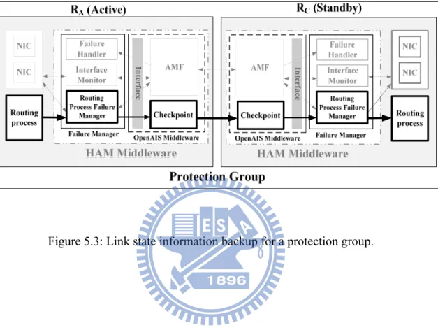
Figure 5.3: Link state information backup for a protection group. ... 29
Figure 6.1: Experimental environment. ... 31
Figure 7.1: An ATCA-based HA-OSPF router consisting of LC, CC and SC. ... 40
Chapter 1
Introduction
With the progress in the broadband network, many people and businesses rely heavily on Internet applications and services. Critical facilities, such as data centers, communication centers, financial trading service centers and telecommunication service centers should ensure a certain degree of operational continuity during the service period. Thus, it is important for a service provider to build a high availability environment to provide continuous services for users, whether to install new components or repair existing components. If a system cannot be accessed, it is said to be unavailable. Generally, the term downtime is used to refer to periods when a network or system is unavailable.
Network availability can be improved either by incremental improvements in component availability or by provision of redundant components in parallel [1][2]. But, it is costly to implement or use high availability components [3]. Mettas used a nonlinear programming algorithm to formulate a cost function [4], which is an exponential behavior and a monotonically increasing function of the component availability. Unfortunately, the cost function shows that the more difficult it is to improve the reliability of the router, the greater the cost [4]. Depending on the design
complexity, technological limitations, and so on, the availability of certain components can be very hard to improve [4].
Therefore, adding redundant routers to a network router to achieve the goal of high availability is a familiar design [5]-[16]. In general, this approach consists of a cluster of routers where one is the active router and the others are on standby. That is, the active router executes the routing process, while a standby router is prepared to take over the active router’s role immediately if the active router failed.
For establishing network router redundancy, VRRP (Virtual Router Redundancy Protocol) [5] and HSRP (Hot Standby Router Protocol) [6] are two most familiar designs. VRRP is a non-proprietary redundancy protocol described in RFC 3768 [5] and HSRP is a Cisco proprietary redundancy protocol described in RFC 2281 [6]. VRRP is based on Cisco's proprietary HSRP concepts. These two technologies are similar in concept, but not compatible.
The increased availability of VRRP is achieved by advertising a "virtual router," which is an abstract object managed by VRRP that acts as a default router for hosts on a shared LAN [5]. The main purpose of the virtual router is that the hosts on the LAN are configured to forward packets to the virtual IP address, rather than to the IP address of the real interface. In VRRP, two or more physical routers are then configured to stand for the virtual router, with only one doing the actual routing at any given time. A standby router, also from the group of routers, monitors the status of the active router so that if the active router becomes inoperative, the standby router automatically begins emulating the virtual router. The host is configured to point to the virtual address so that the packets it sends out of its LAN are always directed to the virtual router which may be any router from the group of routers. If the standby router becomes inoperative or takes over for the active router’s role, other routers in
the group hold an election to determine which of them should take over for the standby router. In this way, the hardware availability can be improved significantly. Note that the concept of the virtual router can also be applied to a server cluster to achieve load balancing [13].
In this dissertation, a 5-tuple availability function, A M N( , , , , ) , is proposed
to determine the minimum required number of standby routers in an HA (High Availability) router for achieving the desired availability (ρ), where M and N are the number of active routers and standby routers, respectively, and λ, μ, and δ are a single router’s failure rate, repair rate, and failure detection and recovery rate, respectively. The availability function can facilitate service providers or network administrators to determine a suitable redundancy model and the minimum required number of standby routers to support their HA routers.
One issue deserved to mention is that a lack of link state information in VRRP, the standby router cannot recover the routing protocol session in real time if it takes over. The standby router needs to generate link state exchange messages with its neighbor routers and to obtain the up-to-date link states of the network. Before the completion of the link state coherence, the standby router cannot take over the role of the active router. To reduce the takeover delay, stateful takeover can be used to decrease the time of link state coherence and to improve the router availability. Ho et al. [12] proposed a router and routing protocol redundancy model to reduce service outage or degradation for a network router and thus to increase service availability on a network due to software and hardware failures of the network router [12]. The active router generates or receives the routing protocol state change and replicates it to the standby router. Because of the replica of the routing protocol state, the standby router can recover and maintain the routing protocol sessions for network devices
immediately if a failure occurs in the active router. Furthermore, the routing protocol states are maintained by the standby router in real-time to handle the dynamic changes created by routing protocols [12]. Because the standby router can reconstruct the routing information from the routing protocol states if it takes over, this model results in significantly less network disconnection time. However, the work by Ho et al. did not mention the takeover delay of their proposed router and the improvement of the router availability.
The industry routers, Cisco ASR-1000 series router [17] and Juniper MX series router [18], can provide hardware level redundancy and support the stateful takeover. Both Cisco ASR-1000 series router and Juniper MX series router have two routers, one active and one standby. The active router replicates the link state information to the standby router to reduce the takeover delay. The standby router can take over the role of the active router immediately if the active router failed. The takeover delays for the Cisco ASR-1000 series router and Juniper MX series router are very small, about 200 ms for Cisco ASR-100 [17] and 300 ms for Juniper MX series router [18]. Although the Cisco ASR-1000 series router and Juniper MX series router have a small takeover delay, they need a specific chassis and a midplane to negotiate and exchange the link state information. In addition, the Cisco ASR-1000 series router is lack of ability for flexible adjustment of the redundancy model [17]. That is, it only supports one active router and one standby router. The Juniper MX series router can adjust the redundancy model flexibility. It supports 2N redundancy, M+N redundancy, and full mesh redundancy models.
Because there is a lack of research on the integration of redundancy model, link state information backup, and failure detection and recovery, we also propose an HA Open Shortest Path First (HA-OSPF) router with High Availability Management
(HAM) middleware which consists of Availability Management Framework (AMF) service [19], Checkpoint service [19], and Failure Manager. The HAM middleware was implemented based on an open source and open architecture project, OpenAIS [19]. The flexible redundancy adjustment and link state information backup can be provided by the AMF service and Checkpoint service, respectively. The Failure Manager can provide procedures to achieve the goal of fast failure detection and recovery. The HAM middleware can provide a complete integration for decreasing network disconnection time and improving network availability effectively. In addition, we have implemented an HA-OSPF router and evaluate the takeover delay of the proposed HA-OSPF router in the OSPF network [20].
The rest of this dissertation is organized as follows. We review the preliminary in section 2. In section 3, we propose a 5-tuple availability function and analyze the HA router availability under a various number of standby routers by using the continuous-time Markov chain. Analytical results are given in section 4. In section 5, we describe the proposed HAM (High Availability Management) middleware design and the procedures of role assignment, routing process status and link state information backup, and failure detection and recovery. Then, in sections 6 and 7, experimental results and field trial results are evaluated and discussed. Finally, we conclude this dissertation in section 8.
Chapter 2
Preliminary
The International Telecommunications Union-Telecommunication Standardization Sector (ITU-T) gives the definition of the reliability and availability in the recommendation E.800. In this section, we will introduce the relationship between failure rate, repair rate, failure detection and recovery rate, and availability.
2.1. Reliability Definitions
Recommendation E.800 of the ITU-T defines reliability as the “ability of an item
to perform a required function under given conditions for a given time interval [21].”
Therefore, for any time interval T = (s, s+t), the system will work properly during the interval (i.e., the reliability R(t) = 1, where t and R(t | s) = 1). Generally, the T
system is assumed to be working properly at time t = 0 (i.e., R(0) = 1), and no system can work forever without failures (i.e., limt→∞ R(t) = 0) [22].
Let random variable X be the lifetime (i.e., time to failure) [22] of a system then
) ( 1 ) Pr( ) (t X t F t R (1)
where F(t) is the system lifetime CDF (cumulative distribution function) [22]. Moreover, the expected lifetime (E[X]) or the mean time to failure of the component is given by [22] is
0 ( ) ] [X R t dt E MTTF (2)Therefore, the system MTTF can be computed from the equations (1) and (2). Suppose the system lifetime is exponentially distributed (i.e., F(t) 1et) [22] with failure rate λ then
t t e e t R( )1(1 ) (3) and
0 1 ] [ dt e X E MTTF t (4)Therefore, if a component obeys an exponential failure rate with parameter λ, then the MTTF (i.e., the expected lifetime [22]) can be determined as 1/λ.
2.2. Availability Definitions
ITU-T Recommendation E.800 given the definition of availability as the “ability
of an item to be in a state to perform a required function at a given instant of time or at any instant of time within a given time interval, assuming that the external resources, if required, are provided [21].” Michael et al. [23] identified the difference
between reliability and availability such is that reliability refers to failure-free operation of the system during an interval, while availability refers to failure-free operation of the system at a given instant of time.
the component is up and 0 otherwise. Then, we suppose A(t) is the instantaneous availability of the system. That is, A(t) is the probability of the system which is properly working at specified time t, i.e.,
)] ( [ ) 1 ) ( Pr( ) (t I t E I t A (5)
Based on the instantaneous availability, the steady state availability, A, can be defined as
) (
lim A t
A t (6)
2.3. Steady-state Availability Definitions
The steady-state availability is the probability of a system that is still available over a long period. The steady-state availability (A) can be expressed as [22][23][24]:
MTTR MTTF MTTF A (7)
where MTTF (mean time to failure) is the arithmetic mean time between failures of a component or system and MTTR (mean time to repair) is the amount of time required to perform corrective maintenance and restore a component or system to operational status. MTTR includes total time required to detect that there is a failure, to repair it, and to place the system back into an operational status.
If the system lifetime is exponential with failure rate λ, and the time-to-repair distribution of the system is exponential with repair rate μ, then equation (7) can be rewritten as [22][23][24] A (8)
Chapter 3
HA Router Model Description and
Analysis
With the design complexity and technology limitations, Mettas used a cost function to show that it is very difficult to improve the availability of the router, the greater the cost [4]. Thus, a feasible way to increase the router availability is to add the standby router to the HA router [5][6][7][9][10]. In this section, we propose a 5-tuple availability function, A M N( , , , , ) , to determine the minimal number of
standby routers (N) in an HA router to achieve the desired availability, under the conditions of the failure rate (λ), repair rate (μ), failure detection and recovery rate (δ), and number of active routers (M). The continuous-time Markov chain (CTMC) [22][25][26] is used to determine the steady-state availability of an HA router with various numbers of active routers and standby routers.
3.1. Continuous-Time Markov Chain for 1+N
Redundancy Model
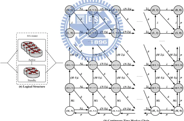
In this section, the continuous-time Markov chain (CTMC) of an HA router with 1+N redundancy model (i.e., one active router and N standby routers) is considered. Figure 3.1 is the state-transition diagram of a CTMC [22][25][26] modeling the failure and repair behavior of an HA router with 1+N redundancy model (i.e. one active and N standby). The failure of the active router will cause the network to recalculate routing path information. To avoid this undesirable situation, each standby router monitors the status of the active router. If a failure occurred in the active router, the standby routers hold an election automatically. Then, one of the standby routers will take over the role of the active router.
Figure 3.1: CTMC for an HA router with 1+N redundancy model.
As shown in Figure 3.1, state (i, j) represents the status of the HA router, where i and j represent the status of active and standby routers, respectively. If i (or j) equal to 1 means the active (or standby) router is working and 0 otherwise. If both i and j equal to 1, it means both the active and standby routers of the HA router are working. If i equal 0 and j equal to 1, it represents the failure of the active router and if i equal to 1 and j equal to 0, it represents the failure of the standby router. Finally, if both i and j
equal to 0, it means the two routers of the HA router are failed.
The state diagram of the CTMC modeling the failure and repair behavior of an HA router with 1+N redundancy model is depicted in Figure 3.1. The active router works properly at state (1, p), where 0 ≤ p ≤ N. The state (0, q) represents the active router failed and the HA router fails (i.e., cannot forward packets). The system detects and recovers the failure with rate δ and will go to state (1, q-1), where 1 ≤ q ≤ N. The state (0, 0) represents that all the router modules of the HA router are failed.
In this dissertation, the time to failure and time to repair of a router module are assumed to be exponentially distributed with mean 1/λ and 1/μ, respectively. In Figure 3.1, when the state transfers from (0, p) to (1, p-1), 0 ≤ p ≤ N, which indicates that a failure has been detected and recovered, and the standby router has taken over the role of the active router. The associated failure detection and recovery rate (δ) is the multiplicative inverse of the mean time that from the active router failed to the standby router detecting that the failure had occurred and being recovered from it. Note that in this dissertation, all failure events are assumed to be mutually independent.
Let π(i, j) denotes the proportion of time that the system is in state (i, j). Note that in the steady state the rate at which transitions into state (i, j) must equal to the rate at which transitions out of state (i, j). Thus, from Figure 3.1, we obtain the following equations for the steady state probabilities:
(N 1) (1, )N (1,N 1) (9)
(N ) (0, )N (1, )N (10)
(0, 0) (0,1) (1, 0)
( ) (1, 0) (1,1) (0, 0) (0,1) (12) (K ) (0, )K (1, ) (K K1) (0,K1), where -1N K 1 (13) ( ) (1, ) ( 1) (1, 1) (1, 1) (0, 1), where -1 1 K K K K k K N K (14)
By solving the preceding set of equations, along with this equation
1 0 0 ) , (1
i N j j i
(15)The CTMC for an HA router with 1+N redundancy can transit into a two-state and two-transition Markov chain [27], as shown in Figure 3.2. One state is the Up with the reward rate λHA; the other state is the Down with the reward rate μHA [27]. λHA and μHA are the equivalent failure rate and the equivalent repair rate of the HA router with 1+N redundancy, which can be determined by applying the aggregation techniques described in [27].
Figure 3.2: Equivalent Markov chain.
Therefore, λHA and μHA of an HA router for the CTMC in Figure 3.1 can be expressed as follows:
N j j N j j N N N N HA 0 ) , 1 ( 0 ) , 1 ( ) 0 , 1 ( ) 1 , 1 ( ) 1 , 1 ( ) , 1 ( ) 0 , 1 ( ) 1 , 1 ( ) 1 , 1 ( ) , 1 ( (16)
N j j N j j N N N N HA 0 ) , 0 ( ) 0 , 0 ( 1 ) , 0 ( ) 0 , 0 ( ) 1 , 0 ( ) 1 , 0 ( ) , 0 ( ) 0 , 0 ( ) 1 , 0 ( ) 1 , 0 ( ) , 0 (
(17)Therefore, from equation (8), the equivalent availability of an HA router (AHA) can be expressed as follows: HA HA HA HA
A
(18)Solving equations (16) and (17), we can get an equivalent availability of an HA router (AHA) based on equation (18) under failure rate (λ), failure detection and recovery rate (δ), and repair rate (μ).
3.2. Continuous-Time Markov Chain for M+N
Redundancy Model
In this section, the continuous-time Markov chain (CTMC) of an HA router with
standby router monitors the status of all active routers. If one of the active routers failed, the standby routers hold an election automatically. Then, one of the standby routers will take over the role of the active router. Figure 3.3 (a) is the logical structure of an HA router with M+N redundancy. The CTMC for an HA router with
M+N redundancy is depicted in Figure 3.3 (b). The active routers work properly at
state (M, p), where 0 ≤ p ≤ N. If the state of an HA router moves from state (i, j) to state (i+1, j-1), it represents there is an active router failed and the system detects and recovers the failure with rate δ, where 0 ≤ i ≤ M-1 and 1 ≤ j ≤ N. State (0, 0) represents that all routers, including active and standby routers, of the HA router failed.
Figure 3.3: Logical structure and CTMC for an HA Router with M + N redundancy. After writing the steady state equations and solving these equations, we obtain
the following equations under the steady state: ((kN) ) ( , ) (k N k1) (k1, ), where 0N k M 1 (19) 0 , 1 : 1 ( ,0) ( 1) ( , ), where 0 1 i j k i j k k k i j k M
(20) 1 ,0 : 1 ( , ) ( 1) ( , ), where 0 1 k i N i M i j M k M k M k i j k N
(21) (k ) (0, )k (1, ) (k k1) (0,k1), where 1 k N1 (22) (( ) ) ( , ) ( 1) ( 1, ) ( 1) ( , 1) ( 1, 1), where 1 1 and 1 1 i j i j i i j j i j i j i M j N (23) (MN) ( , )M N ( ,M N1) (24) 0 0( , ) 1
M N i ji j
(25)Therefore, λHA and μHA can be written as follows:
( , ) ( , 1) ( , 1) ( , 0) ( , ) ( , 1) ( , 1) ( , 0) ( , ) 0 ( , ) 0
M N M N M M HA M N M N M M N M j j N M j j
M
M
M
M
M
M
(26)
( 1, ) ( 1, 1) ( 1, 1) ( 1, 0) ( 1, ) ( 1, 1) ( 1, 1) ( 1, 0) ( 1, ) ( 1, 0) ( 1, 0) ( 1, 0) 1 ( 1, ) 0 ( 1, ) ( 1, 0 0HA M N M N M M M N M N M M N M j M M M j N M j j N M j M j
) ( 1, ) 0 N M j j
( 1, 0) ( 1, ) 0 M N M j j
(27)Solving equations (26) and (27), we can also get an equivalent availability of an HA (AHA) router with M+N redundancy model based on equation (18) under failure rate (λ), failure detection and recovery rate (δ), and repair rate (μ).
3.3. Formalizing a 5-tuple Availability
Function
Based on the above discussion, we propose a 5-tuple availability function,
( , , , , ),
A M N to determine the minimum required number of standby routers (N) need to be allocated in an HA router to achieve the desired availability (ρ). In addition, as shown in equation (28), the equivalent availability of an HA router (AHA) is equal to the derived value of the 5-tuple availability function.
( , , , , ) HA
A A M N (28)
Therefore, problem P1 can be formally defined as follows: Problem P1: Minimize N subject to
, where 0
HA HA HA HAA
N
M
(29)where μHA and λHA are the equivalent repair rate and equivalent failure rate of an HA router.
Chapter 4
Analytical Results
In this section, we want to find the most cost-effective redundancy model for the HA router such that its availability meets the requirement of the carrier-grade availability (ρ = 99.999%). The parameter settings of μ, λ, and δ are given as follows. Based on the data from Cisco, we set μ = 0.25 times/hour (i.e., MTTR (1/μ) is equal to 4 hours). The MTTR of a router is assumed to the time it takes to have a spare part and a knowledgeable person arrive to repair. Three MTTFs, low MTTF (1/λ = 10000 hours), high MTTF (1/λ = 100000 hours) and Cisco carrier grade router’s MTTF (1/λ = 61320 hours) are considered.
4.1. Numerical Analysis of Minimal Required
Standby Routers for 1+N Redundancy Model
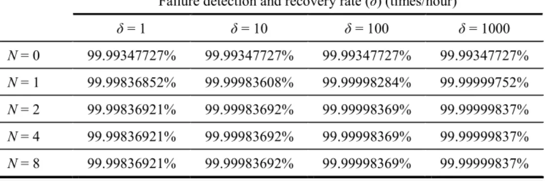
Solving equations (16) and (17) we can get the availabilities of an HA router by using equation (18) under various failure detection and recovery rates, and a different number N of standby routers, as shown in Table 4.1. From Table 4.1, an HA router with 1 + 1 redundancy (i.e., N = 1) will meet the five-nine availability if δ is greater
than 10 times/hour. In general, δ is much larger than 10. For example, in Table 6.3, the
δ for the VRRP router is at least 248 times/hour and the δ for the proposed HA-OSPF
router is at least 2903 times/hour. For a commercial router, such as a Cisco ASR 1000 Series router, its δ is 1800 times/hour [17]. Thus, we conclude that an HA router with 1+1 redundancy is preferred, which will meet the five-nine availability.
In addition, we also found that the failure detection and recovery rate (δ) is a key parameter to improve the availability of an HA router. To have high availability, δ is the larger the better. Note that, for an HA router with 1+1 redundancy, to obtain five-nine availability, the minimum δ is 1.632 times/hour for 1/λ = 7 years and 1/μ = 4 hours [28]-[30]. In Sections 5 and 6, we will show that the experimental δ’s for a PC-based and an ATCA-based HA routers with 1+1 redundancy are 2903 times/hour and 3377 times/hour for hardware failures, respectively, which are much higher than the minimum δ we just mentioned. For software failures, the experimental δ’s are even larger.
Table 4.1: The availability of an HA router (AHA) for a different number of standby routers and various failure detection and recovery rates under 1/λ = 7 years and 1/μ =
4 hours [28]-[30].
Failure detection and recovery rate (δ) (times/hour)
δ = 1 δ = 10 δ = 100 δ = 1000 N = 0 99.99347727% 99.99347727% 99.99347727% 99.99347727% N = 1 99.99836852% 99.99983608% 99.99998284% 99.99999752% N = 2 99.99836921% 99.99983692% 99.99998369% 99.99999837% N = 4 99.99836921% 99.99983692% 99.99998369% 99.99999837% N = 8 99.99836921% 99.99983692% 99.99998369% 99.99999837%
4.2. Numerical Analysis of Minimal Required
Standby Routers for M+N Redundancy Model
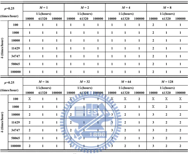
The failure detection and recovery rate (δ) is set to 100, 1000, 10000, and 100000 times/hour. In addition, three failure detection and recovery rates which were measured from the proposed HA router, are also considered. Those includes δ=11429 times/hour for hardware failures only, δ=58065 times/hour for software failures only, and δ=34747 times/hour for hardware and software failures (see section 7). The number of active routers M varies from 1, 2, 4,…, to 128. Table 4.2 shows the analytical results to determine the minimum required number of standby routers (N) for the proposed HA router under various μ, λ, δ, and M.
Table 4.2: The minimum required standby routers (N) for an HA router to achieve the goal of carrier-grade availability (ρ = 99.999%).
μ=0.25
(times/hour)
M = 1 M = 2 M = 4 M = 8
1/λ(hours) 1/λ(hours) 1/λ(hours) 1/λ(hours)
10000 61320 100000 10000 61320 100000 10000 61320 100000 10000 61320 100000 δ (tim es/ ho ur) 100 1 1 1 1 1 1 1 1 1 2 1 1 1000 1 1 1 1 1 1 1 1 1 2 1 1 10000 1 1 1 1 1 1 1 1 1 2 1 1 11429 1 1 1 1 1 1 1 1 1 2 1 1 34747 1 1 1 1 1 1 1 1 1 2 1 1 58065 1 1 1 1 1 1 1 1 1 2 1 1 100000 1 1 1 1 1 1 1 1 1 2 1 1 μ=0.25 (times/hour) M = 16 M = 32 M = 64 M = 128
1/λ(hours) 1/λ(hours) 1/λ(hours) 1/λ(hours)
10000 61320 100000 10000 61320 100000 10000 61320 100000 10000 61320 100000 δ ( tim es /h ou r) 100 Χ 1 1 Χ 1 1 Χ Χ 2 Χ Χ Χ 1000 2 1 1 2 1 1 3 2 1 Χ 2 2 10000 2 1 1 2 1 1 3 2 1 3 2 2 11429 2 1 1 2 1 1 3 2 1 3 2 2 34747 2 1 1 2 1 1 3 2 1 3 2 2 58065 2 1 1 2 1 1 3 2 1 3 2 2 100000 2 1 1 2 1 1 3 2 1 3 2 2 Χ: no feasible solution
From the analytical results, we also found that the minimum required number of standby routers (N) can be decreased when the failure rate (λ) or the failure detection and recovery rate (δ) of the router decreases or increases, respectively. It also shows that the failure detection and recovery rate (δ) of a router is a key parameter for reducing the minimum required number of standby routers in an HA router.
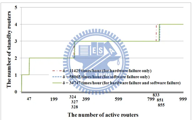
Figure 4.1 shows the relationship between the minimum required number of standby routers and the number of active routers for an HA router with 1/λ, 1/μ, and ρ
being set to 61320 hours, 4 hours (from Cisco [28][29][30]), and 99.999% respectively. Based on Figure 4.1, service providers or network administrators can determine the appropriate number of standby routers for constructing an HA router under various numbers of active routers and the desired availability (ρ). For instance, an HA router needs only one standby router to meet the requirement of carrier-grade availability (ρ = 99.999%) when the number of active routers is not greater than 47, as shown in Figure 4.1.
Figure 4.1: The minimum required number of standby routers for an HA router under various numbers of active routers and failure detection and recovery
rates (with ρ = 99.999%).
4.3. Computational Complexity
For a given N, we evaluate A M N( , , , , ) and check to see if
( , , , , )
A M N or not. By this way, the minimum value of N such that
( , , , , )
A M N can be found. In each iteration, we have to solve the equations (19) ~ (25) for evaluatingA M N( , , , , ) . Note that the equations (19) ~ (25) can be
rewritten as a system Ax = b of linear equations where A is n×n matrix. The system Ax = b can be solved by Gaussian elimination with time complexityO n . Thus, we can ( )3
apply Gaussian elimination to the equations (19) ~ (25) with n = (M+1)(N+1). That is, it takes O M([( 1)(N1)] )3 O MN(( ) )3
time to evaluate A M N( , , , , ) in each iteration. The number of iterations needed for the binary search isO(logM). Therefore, the total time for solving Problem P1 isO M N( 3 3logM . )
Chapter 5
Proposed HA Router Design
The proposed 5-tuple availability function shows that the failure detection and recovery rate (δ) is a key parameter to increase the availability of an HA router. In order to increase the failure detection and recovery rate, a High Availability Management (HAM) middleware was designed which can decrease the takeover delay (1/λ) and meet the requirement of carrier-grade availability with five-nine. In this section, we are going to discuss the function of each component in the proposed HAM middleware design.
5.1. HAM Middleware Design
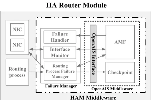
As shown in Figure 5.1, the HAM middleware (within the two-dot chain square) includes two different entities, OpenAIS middleware and Failure Manager. The OpenAIS middleware is a cluster middleware defined in the Service Availability
Forum (SAF) Application Interface Specification [19]. In this dissertation, two
services, AMF service and Checkpoint service, were used to construct the HA-OSPF router. The processes in the router can communicate with AMF service and
Checkpoint service through the interface, which is a set of APIs (Application Programming Interface) and callback functions, of OpenAIS middleware. The functions of AMF service and Checkpoint service are described as follows:
AMF service: It provides role assignment and health check. The AMF service can provide three kinds of redundancy model, 2N redundancy, M+N redundancy, and N-way redundancy. When a router first starts, the AMF service will assign a role, active or standby, to the router. The AMF service of the active router sends a heartbeat message to the standby router(s) periodically to report its health status. If the standby router does not hear the heartbeat message from the active router within a down check interval (e.g., 1 second, which is a default value), it will assume the active router has failed and the AMF service will find a router from the standby router(s) to take over the role of the active router.
Checkpoint service: It provides routing process status and link state information exchange service between active and standby routers. Through this service, the active router can replicate its routing process status and link state information to the standby router(s). The information can help a standby router reduce the takeover delay and improve the availability when it takes over.
HA Router Module
AMF Checkpoint NIC NIC Routing process HAM Middleware Interface Monitor Routing Process Failure Manager Failure Handler Failure Manager OpenAIS MiddlewareFigure 5.1: The components of an HA router module.
Moreover, the proposed Failure Manager is designed to monitor the status of NICs and routing process and to backup the routing process status and link state information. The Failure Manager will register itself to the OpenAIS middleware and get the permission for using the AMF service and Checkpoint service. The Failure Manager consists of following three modules:
The Routing Process Failure Manager takes care of the routing process operations, informs the AMF service if a failure in the routing process is detected, and replicates the routing process status and link state information to the Checkpoint service.
The Interface Monitor checks the health status of the network interface cards (NICs) and informs the AMF service if any NIC failure occurs. The Failure Handler has a set of callback functions. When the AMF service
predefined callback function to handle the failure. For instances, the callback function will reinitialize the failed process or device if the failure can be determined by the Failure Manager (e.g., the routing process or an NIC failed). However, if the failure (e.g., AMF service failed or HA router failed) cannot be determined by the Failure Manager, the failed router will be restarted by the callback function after a down check interval and the standby router will send a report to the network administrator.
5.2. HAM Middleware Operation Procedures
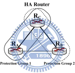
The operation procedures of the HAM middleware can divide into three parts: Role assignment: We use M = 2 and N = 1 as an example to illustrate an HA
router with M+N redundancy and it can be easily extended to the general case. As shown in Figure 5.2, there exist two protection groups (e.g., protection groups (RA, RC) and (RB, RC)) in an HA router. A protection
group [19] is defined as a pair of routers, one active and one standby. When
the router in an HA router is started, it will get the role, active or standby, firstly. The standby router monitors the active router’s health status in each protection group. If an active router fails, the standby router will take over the role of the active router. Note that at this moment all protection groups are lost. After a failed router having been repaired, it will re-initiate and execute the role assignment operation to form a protection group again. Like VRRP, the active router and the standby router in the same protection group use the private IP addresses to communicate with each other. Moreover, the active router uses the real IP address to communicate with its
adjacent routers. As soon as the standby router takes over, the standby router changes its IP addresses to the real IP addresses. For a broadcast network (e.g., Ethernet), the standby router will send a gratuitous ARP [31] message to the network. The gratuitous ARP message is used to ask its neighbors to bind the MAC address of the standby router to the real IP address. Thus, the standby router can receive and forward the packets continuously when it takes over.
Figure 5.2: The logical structure of an HA router with 2+1 redundancy.
Routing process status and link state information backup: Figure 5.3 shows how routing process status and link state information flow from the active router to standby router. The Routing Process Failure Manager of active router gets the routing process status and link state information and replicates those to the standby router through the Checkpoint service. Then, the standby router receives and saves the routing process status and the link state information. When the standby router takes over, the information can
help the standby router to decrease the takeover delay and improve the availability of the HA router.
Chapter 6
Experiments
In Figure 4.1, we have shown that an HA router with M+1 redundancy (for M ≦ 47) is the recommended scheme to meet the carrier-grade (ρ = 99.999%) availability under an appropriate failure rate (λ), failure detection and recovery rate (δ), and repair rate (μ). In this section, we will actually measure the failure detection and recovery rate (δ) of the proposed HA-OSPF router with M+1 redundancy on an OSPF network (M = 2 in our experiments for illustration). We will show the takeover delay of the proposed HA-OSPF router with HAM middleware is smaller than those of an industry standard approach, Cisco ASR-1000 router [17], and a VRRP router [5]. The takeover delay (the multiplicative inverse of the failure detection and recovery rate) is defined as the latency from the active router of the HA-OSPF router failed to the standby router of the HA-OSPF router taking over and recovering from the failure.
6.1. Experimental Setup
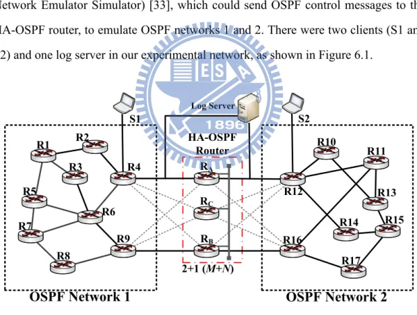
We have implemented an HA-OSPF router on a PC-based environment. We used the 2+1 redundancy model as an example to construct the HA router to verify the
correctness of the proposed HA-OSPF router. To implement the HA-OSPF router with 2+1 redundancy, three desktop PCs with Intel Pentium 4 3.0 GHz processors and 512 MB memories connected via Ethernet were used to emulate an HA-OSPF router. That is, the HA-OSPF router consists of three routers RA, RB and RC, as shown in Figure 6.1. A Linux operating system and GNU Zebra [32] were selected as the developing platform for the PC-based HA-OSPF router. The GNU Zebra is a well-known open source software that manages the TCP/IP based routing protocol. Suppose that RA and RB are active routers and RC is a standby router when the HA-OSPF router is first started. Then, we used two PCs which run IMUNES (Integrated Multiprotocol Network Emulator Simulator) [33], which could send OSPF control messages to the HA-OSPF router, to emulate OSPF networks 1 and 2. There were two clients (S1 and S2) and one log server in our experimental network, as shown in Figure 6.1.
2+1 (M+N)
OSPF Network 1
OSPF Network 2
R3 R4 R7 R6 R9 R8 R10 R12 R11 R14 R13 R16 R15 R17 R1 R5 R2 RA RB RC HA-OSPF Router S1 S2 Log Server
In the experiment, S1 sent UDP data packets with specific sequence numbers to S2 to examine the network connectivity (see Figure 6.1). The log server was used to record the sequence number and timestamp of each packet that it received. If S1 sends a packet to S2, it also has to send a copy of the packet to the log server. Then, S2 will forward the packet it received from S1 to the log server. During the takeover period, the network will be disrupted. The log server will not receive any packets transferred from S2. After the standby router takes over the role of the active router, the log server will continue to receive packets from S2. In this way, the takeover delay can be determined. The default parameter values for the OSPF routing protocol and HAM middleware are listed in Table 6.1 [19][20][28][29][30]. The Hello interval is the number of seconds this router waits before sending out the next Hello packet [19][20]. If a router does not receive a Hello packet from a neighbor router within a fixed amount of time, the router modifies its topological database to indicate that the neighbor router is not operational. The time that the router waits is called the router dead interval. By default, this interval is 40 seconds (four times the default Hello interval) [19][20]. Based on Cisco data, the MTTF (1/λ) and MTTR (1/μ) of a commercial router need at least 7 years (i.e., 61320 hours) and not exceed 4 hours, respectively [28][29][30]. The default values for the down check interval of AMF service and polling interval of the Failure Manager are 1000 ms and 100 ms, respectively [34]. The down check interval is a period of time in which the standby router has to hear at least one heartbeat from the active router; otherwise, the standby router assumes it has failed. The polling interval is a period of time in which the Routing Process Failure Manager and the Interface Monitor check the status of routing process and the NICs, respectively.
Table 6.1: Default parameter values [19][20][28][29][30][34]. Router dead interval of OSPF 40 sec
Hello interval 10 sec
Down check interval of AMF service 1000 ms Polling interval of Failure Manager 100 ms
MTTF(1/λ) 7 years (61320 hours)
MTTR(1/μ) 4 hours
6.2. Experimental Results
First, we will show that the failure detection and recovery time (i.e., takeover delay) is not affected too much by the redundancy model used in the HA router. The takeover delays for the proposed HA-OSPF router under various redundancy models are shown in Table 6.2 with the down check interval of 1000 ms and the polling interval of 100 ms for a hardware failure and software failure, respectively. From Table 6.2, the takeover delay for a hardware failure (a software failure) of the proposed HA-OSPF router with 1+1, 2+1, and 2+2 redundancy are 565 ± 3 ms, 569 ± 3 ms, and 576 ± 4 ms (110 ± 2 ms, 112 ± 3 ms, and 118 ± 4 ms), respectively. The experimental results show that the redundancy model of the HA-OSPF router does not affect too much the takeover delay. Therefore, the 2+1 redundancy model, which a more cost-effective configuration, was used to measure takeover delays of the proposed HA-OSPF router in the subsequent experiments.
Table 6.2: Takeover delay (ms) of the proposed HA-OSPF router under various redundancy models.
Redundancy Model
1+1 2+1 2+2
Hardware failure 565 ± 3 569 ± 3 576 ± 4
Software failure 110 ± 2 112 ± 3 118 ± 4
Then, we investigate how the takeover delay is affected by the state information backup of the standby router. We did not measure the takeover delay of Cisco ASR-1000 series router due to lack of facilities. However, in [17], it describes that if an active router of Cisco ASR-1000 series router experiences a hardware or software failure that makes it unable to forward traffic and a standby router of Cisco ASR-1000 series router is configured, the standby router becomes the active router within 200 ms [17]. Therefore, only the following two cases were implemented and evaluated as follows:
VRRP-based router with 2+1 redundancy: The active routers do not save any state information in the standby router.
Proposed HA-OSPF router with 2+1 redundancy: Each active router backs up its full state information, including its link states, LSDB (link state database), and routing table to the standby router.
In addition, two types of failures were considered. One is when R2 halts by an unexpected power down (referred as a hardware failure), and the other is when an OSPF process failed (referred to as a software failure). First, in Figure 6.1, UDP packets traveled along path S1, R4, RA, R12, S2 until the active router failed. After
R12 and R4 reestablished their routing tables, the UDP packets could go through the path S1, R4, RC, R12, S2.
The takeover delays for the proposed HA-OSPF router with 2+1 redundancy and VRRP-based router with 2+1 redundancy are shown in Table 6.3. The takeover delay for a hardware failure (a software failure) of the VRRP-based router and the proposed HA-OSPF router were 14511 ± 36 ms and 569 ± 3 ms (13383 ± 3 ms and 112 ± 3 ms), respectively. Experimental results show that the takeover delays of the proposed HA-OSPF router were reduced by 96.08% and 99.16% compared to those of VRRP for a hardware failure and a software failure, respectively. The proposed HA-OSPF router with full state information backup demonstrates its benefits.
Table 6.3: Takeover delays (ms) and failure detection and recovery rates (times/hour) for a HA-OSPF router and a VRRP-based router.
Emulation Scenario
VRRP HA-OSPF router Hardware failure
Takeover delay (ms) 14511 ± 36 569 ± 3 Failure detection and
recovery rate (times/hour) 248 6327
Software failure
Takeover delay (ms) 13383 ± 3 112 ± 3 Failure detection and
recovery rate (times/hour) 269 32143
Next, we measured the takeover delay for the PC-based HA-OSPF router due to a software failure under various polling intervals. Table 6.4 shows that the takeover delays (failure detection and recovery rates) due to a software failure were, 62 ± 1 ms (δ = 58065 times/hour), 112 ± 3 ms (δ = 32143 times/hour), and 170 ± 2 ms (δ = 21176 times/hour) for three polling intervals, 50 ms, 100 ms, and 200 ms, respectively.
Experimental results show that the takeover delay depends on the polling interval. We found that the shorter the polling interval, the faster the takeover delay (i.e., failure detection and recovery time) is.
Table 6.4: Takeover delays (ms) and failure detection and recovery rates (times/hour) due to a software failure (OSPF process down) under various polling intervals.
Polling interval
50 ms 100 ms 200 ms
Takeover delay (ms) 62 ± 1 112 ± 3 170 ± 2 Failure detection and
recovery rate (times/hour) 58065 32143 21176
We then investigated the takeover delay of the proposed HA-OSPF router due to a hardware failure under different down check intervals. In Table 6.5, the takeover delays (failure detection and recovery rates) due to a hardware failure under down check intervals of 500 ms, 1000 ms, and 2000 ms were 315 ± 2 ms, 569 ± 3 ms, and 1087 ± 9 ms (11429 times/hour, 6327 times/hour, and 3312 times/hour), respectively. That is, the smaller down check intervals result in the shorter takeover delays.
Table 6.5: Takeover delays (ms) and failure detection and recovery rates (times/hour) due to a hardware failure under various down check intervals.
Down check interval
500 ms 1000 ms 2000 ms
Takeover delay (ms) 315 ± 2 569 ± 3 1087 ± 9 Failure detection and
recovery rate (times/hour) 11429 6327 3312
Table 6.6 summarized the comparisons of the proposed HA-OSPF router, VRRP router, Cisco ASR-1000 series router, and Juniper MX series router in terms of cost, takeover delay, implementation flexibility, flexible redundancy model, stateful backup, open specification and open source, storage overhead, and bandwidth overhead. The router which supports stateful backup needs the additional bandwidth and storage to transfer and save the routing process status and link state information, respectively. As shown in Table 6.6, the bandwidth overhead is the amount of bandwidth (in bps) used by the active router transmitting the heartbeat and replicating its routing process status and the link state information to the standby router. The storage overhead is the number of bytes used by standby router saving the routing process status and link state information of active router. Moreover, since the proposed HA-OSPF router is constructed based an open source and open architecture specification, OpenAIS, and it does not need the specific chassis and hardware to achieve the goal of carrier-grade availability, the cost and implementation difficulty for constructing the proposed HA-OSPF router are less than those of the Cisco ASR-1000 series router and Juniper MX series router. Furthermore, from experimental results, we found that the takeover delay of the proposed HA-OSPF router were reduced 6%, 37.3%, and 98.6% compared to those of the Cisco-ASR 1000 series router, the Juniper MX series router, and the VRRP router, respectively. Therefore, we concluded that the proposed HA-OSPF router is more feasible than VRRP-based router, Cisco ASR-1000 series router, and Juniper MX series router to construct a high availability network.
Table 6.6: The comparisons of the proposed HA-OSPF router, VRRP router, Cisco ASR-1000 series router, and Juniper MX series router.
Scheme HA-OSPF router (proposed) VRRP router Cisco ASR-1000 series router Juniper MX series router
Cost Medium Low Very High Very High
Takeover delay 189 ms *1 13383 ms about 200 ms 300 ms *2
Implementation
flexibility Easy Easy Hard (Cisco IOS) Hard (Juniper JUNOS)
Flexible redundancy
model Yes Yes No Yes
Stateful backup Yes No Yes Yes
Open specification/
source Yes Yes
No, proprietary (Cisco IOS)
No, proprietary (Juniper JUNOS)
Storage overhead*3 ((NM)×P×Q)/8 bytes No (P×Q)/8 bytes ((NM)×P×Q)/8 bytes
Bandwidth overhead*4 ((NM)×P×Q/T
C)+(K/TH) bps (K/TH) bps (P×Q/TC)+(K/TH) bps ((NM)×P×Q/TC)+(K/TH) bps
*1 189 ms = (62 ms + 315 ms)/2, where 62 ms is for a software failure (Hello interval is 50 ms) and 315 ms is for a hardware failure
(Hello interval is 500 ms), see section 6.
*2 The takeover delay of the Juniper MX series router is three times of Hello intervals (Hello interval is 100 ms ~ 65535 ms).
*3 P is the number of routers in the network and Q is the number of bits of process status and link state information for each router.
*4 T
Chapter 7
Field Trial Results
This section describes how to implement the HA-OSPF router on an ATCA (Advanced Telecom Computing Architecture) platform and experimental results of the field trial is given. ATCA technology [34][35] allows new communication equipment to be constructed with great attributes such as high performance, high availability, adaptability for adding new features, and lower cost of ownership. An open architecture solution using the ATCA technology can improve service availability. Thus, industries often use ATCA open architecture combined with their own software solutions to quickly deploy competitive services.
Three types of ATCA cards (i.e., line card, control card, and switch card) were used to build an ATCA-based HA-OSPF router, as shown in Figure 7.1 [34][35]. Based on the operating function of ATCA cards and the concepts of ForCES (Forwarding and Control Element Separation) [36][37][38], the router can be separated into two parts: control plane and forwarding plane. The control plane service was designed to send control messages and to manage routing information. The forwarding plane service is to decide the outgoing interface for each incoming packet. In general, the forwarding plan looks up the destination address of an
incoming packet, refers to a routing table (or forwarding table), finds an outgoing interface for the incoming packet, and then sends the incoming packet through the outgoing interface.
Figure 7.1: An ATCA-based HA-OSPF router consisting of LC, CC and SC [34][35].
The details of each ATCA card are described as below [34][35]:
Line Card (LC): The LC belongs to the forwarding plane and was designed for the basic packet forwarding function. When the LC receives OSPF control
packets from its neighbor router, the LC will forward the packets to the control card. Then, if the LC receives the packets, it will forward the packets to correct destinations according to the routing table.
Control Card (CC): It belongs to the control plane. The CC performs the OSPF routing protocol based on a received OSPF control packet. When the CC receives an OSPF control packet from its neighbors, the CC resets the waiting timer (e.g., the Hello message timer of its neighbor). If the network topology has changed, the CC recalculates the routing table. After that, the CC updates the LC’s forwarding table. In addition to the OSPF process, the HAM middleware and OpenAIS middleware have been installed in the CC to perform the state information backup and failure detection and recovery functions.
Switch Card (SC): The SC belongs to the forwarding plane. It switches packets to a correct card (LC or CC) through the backplane. For example, as shown in Figure 7.1, control packets received by the LC will be forwarded to the SC via the base interface and then the SC switches the packets to the CC. Data packets received by the LC will be forwarded to the SC via a fabric interface and then the SC switches these packets to the LC.
In our system, an AdvancedTCA compliant processor card, named as aTCA-6890 [35], was used as a control card to build a router. The aTCA-6890 is available in a dual processor configuration with the Low Voltage Intel 3.2 GHz Xeon processor and 800 MHz System Bus. The aTCA-6890 also features the Intel E7520 chipset and 4 GB DDR-400 memories. Peripherals include six Gigabit Ethernet ports and two 10/100/1000 Mbps Ethernet maintenance ports.
Remind that we used two PCs connected via the Ethernet to emulate a PC-based HA-OSPF router in the previous experiment; our HA-OSPF router can be easily
![Figure 3.1 is the state-transition diagram of a CTMC [22][25][26] modeling the failure and repair behavior of an HA router with 1+N redundancy model (i.e](https://thumb-ap.123doks.com/thumbv2/9libinfo/8760939.208161/23.892.140.761.532.769/figure-transition-diagram-modeling-failure-repair-behavior-redundancy.webp)
![Table 6.1: Default parameter values [19][20][28][29][30][34].](https://thumb-ap.123doks.com/thumbv2/9libinfo/8760939.208161/46.892.209.627.198.375/table-default-parameter-values.webp)
