Synthesis and characterization of organic – inorganic hybrid thin films
from poly(acrylic) and monodispersed colloidal silica
Yang-Yen Yu
a, Ching-Yi Chen
a, Wen-Chang Chen
a,b,*
a
Department of Chemical Engineering, National Taiwan University, Taipei 10617, Taiwan, ROC
b
Institute of Polymer Science and Engineering, National Taiwan University, Taipei 10617, Taiwan, ROC Received 26 August 2002; received in revised form 29 October 2002; accepted 5 November 2002
Abstract
Hybrid thin films containing nano-sized inorganic domain were synthesized from poly(acrylic) and monodispersed colloidal silica with coupling agent. The 3-(trimethoxysilyl)propyl methacrylate (MSMA) was bonded with colloidal silica first, and then polymerized with acrylic monomer to form a precursor solution. Then, the precursor was spin coated and cured to form the hybrid films. The silica content in the hybrid thin films was varied from 0 to 50 wt%. The experimental results showed that the coverage area of silica particle by the MSMA decreased with increasing silica content and resulted in the aggregation of silica particle in the hybrid films. Thus, the silica domain in the hybrid films was varied from 20 to 35 nm by the different mole ratios of MSMA to silica. The results of scanning electron microscope, transmission electron microscope, and elemental analysis support the above results. The prepared hybrid films from the crosslinked acrylic polymer moiety showed much better film uniformity, thermal stability and mechanical properties than the poly(methyl methacrylate) (PMMA) based hybrid materials. Large pin-holes were found in the PMMA – silica hybrid films probably due to the significant difference on thermal properties between the two moieties or the evaporation of solvent. The refractive index decreased linearly with increasing the silica fraction in the hybrid films. Excellent optical transparence was obtained in the prepared hybrid films. These results show that the hybrid thin films have potential applications as passive films for optical devices.
q2002 Elsevier Science Ltd. All rights reserved.
Keywords: Acrylic/silica hybrid; Microstructure; Optical properties
1. Introduction
Organic – inorganic hybrid materials have been exten-sively studied recently[1 – 3]. The properties of the hybrid materials could be tuned through the functionality or segment size of each component, including thermal, mechanical, electronic, optical, and optoelectronic proper-ties. The applications of the hybrid materials as passive or active layer in optoelectronic devices have been reported in the literature, including protective coating [4], high refractive index films [5 – 8], contact lenses [9], thin film transistor [10], light-emitting diodes [11 – 13], solar cell
[14], optical waveguides materials [15 – 16], and photo-chromic materials[17].
One of the widely studied hybrid materials is poly (methyl methacrylate)(PMMA)/inorganic oxide. PMMA
has been widely used in optical devices due to its excellent optical properties and processibility. However, its thermal and mechanical properties have limited its applications. One possible solution to address the above problems is to hybridize with inorganic oxides such as silica or titania. The PMMA – silica hybrid materials have been extensively studied[18 – 25]. The silica network in the hybrid materials reported previously was prepared from alkoxysilanes
[18 – 24]. The size distribution of the inorganic segment in the hybrid materials has not been precisely controlled, which could be very important for specific optical applications. One possible solution is to use monodispersed colloidal silica instead of preparing silica network from alkoxysilanes. The composite films prepared from mono-dispersed colloidal silica and PMMA have been studied by Ford and his coworkers for the application of narrow bandwidth optical filters [19,20,27,28]. In these studies, colloidal silica with the size larger than 100 nm is required to diffract the light. However, the preparation of acrylic
0032-3861/03/$ - see front matter q 2002 Elsevier Science Ltd. All rights reserved. PII: S 0 0 3 2 - 3 8 6 1 ( 0 2 ) 0 0 8 2 4 - 8
www.elsevier.com/locate/polymer
* Corresponding author. Tel.: þ 23628398; fax: þ 886-2-23623040.
polymer/nanoscale colloidal silica composite films has not been addressed in these studies. Such composite films could have important applications for transparent optical coating or refractive index tuning films. In this case, the silica size should be less than 50 nm to avoid the scattering loss. Besides, the thermal stability of PMMA limits the curing temperature of the hybrid materials below 100 nm. Hence, the incomplete condensation of Si – OH might exist and affect the optical properties. Therefore, highly corsslinked acrylic polymers might be necessary for the organic moiety. Furthermore, the effect of the coupling agent or silica content on the structure and properties of the composite films has not been fully explored previously.
In this study, poly(acrylic)-silica hybrid thin films were prepared from various acrylic monomers, monodispersed colloidal silica with a coupling agent. It was a combination of the sol – gel reaction, thermal polymerization and spin coating. The example of preparing the trialkoxy capped PMMA – silica hybrid films is shown inFig. 1. Three kinds of acrylic monomers were used in the present study including single functional acrylate of methyl methacrylate (MMA), a bi-functional acrylate of ethylene glycol dimethacrylate (EDMA), and a tri-functional acrylate of trimethylolpropane triacrylate (TMPTA). The coupling agent was 3-(trimethoxysilyl)propyl methacrylate (MSMA). Monodispersed colloidal silica of 12 nm was used for the
preparation of the inorganic component. The formulation for preparing the hybrid films is shown inTable 1. The S0 – S50 and DT0 – DT50 represent the hybrid materials synthesized from the MMA and EDMA/TMPTA, respec-tively. The mixture of EDMA/TMPTA was used to prevent the fast polymerization if only TMPTA was used for the hybrid materials. The chemical structures, morphology, thermal properties, mechanical and optical properties of the prepared hybrid thin films were examined. The effects of the MSMA and silica content on the structure and properties of the hybrid thin films were also discussed.
2. Experimental
2.1. Materials
Methyl methacrylate (MMA, 99%, Aldrich), ethylene glycol dimethacrylate (EDMA, 98%, Aldrich), trimethylol-propane trimethacrylate (TMPTA, 90%, Aldrich), 3-(tri-methoxysilyl)propyl methacrylate (MSMA, 98% Aldrich), colloidal silica (Nissan Chemical Industries, 12 nm, 30 wt% in MIBK), benzoyl peroxide (BPO, Acros), and tetrahydro-furan, (THF, 99.9%, Acros) were used for the synthesis of hybrid thin films.
2.2. Preparation of colloidal MSMA-silica
3-(trimethoxysilyl)propyl methacrylate (MSMA), 12 nm colloidal silica, de-ionized water and THF were mixed at the various compositions as shown in Table 1. Then, the reaction mixture was poured into a three-necked reactor to proceed the hydrolysis/condensation reaction. The reaction temperature was maintained at 60 8C and the solution was stirred under a nitrogen flow for 2 h to obtain the colloidal MSMA-silica solution.
2.3. Preparation of hybrid poly(acrylic) – silica films The precursor solution for preparing the hybrid films was obtained according to the composition shown in Table 1. The experimental procedures are described below. The colloidal MSMA-silica obtained in the procedure of 2.2 was subsequently mixed with a homogeneous THF solution of the acrylate monomer (MMA, EDMA, or TMPTA) and the initiator, BPO, to proceed the polymerization reaction under nitrogen purging. The reaction temperature was maintained at 60 8C for 3 h (S0 – S50) and 1.5 h (DT0 – DT50), respectively. Then, the reaction solution was spin coated on a 6 in. silicon wafer for 20 s at the speed of 3000 rpm. The coated thin film was then cured on a hot plate at 80 8C for 30 min, 150 8C for 1 h, and 200 8C for 2 h, respectively. For the case of thick films, the coating liquid was concentrated under room temperature to remove the solvent THF using a rotary vacuum evaporator before spin coating. The curing process was the same as for the case of thin films.
2.4. Characterization
IR spectra of the prepared thin films were obtained on a
KBr pellet using a Jasco Model FTIR 410 spectrophotomer. The 13C and 29Si NMR spectra of the solid-state hybrids were determined (Bruker, DSX-400 WB) with crosspolar-ization combined with the magic angle spinning (CP/MAS) technique. The measured condition of the29Si NMR spectra at 79.4 MHz were as follows: 200 – 300 mg; 1H 408 pulse width: 2.5 ms; spinning frequency: 7 kHz; and recycle time: 15 s. The fracture surfaces of hybrid thin films were examined on the Hitachi H-2400 Scanning Electron Microscope (SEM). The particle sizes of the colloidal particle were measured by the Hitachi H-7100 transmission electron microscope (TEM).
The contents of C, H and N in the prepared materials were measured by element analysis using a Neraeus VarioEL-III Element Analyzer. Elemental analysis result was used to get the idea of the relative shell thickness of the MSMA and MMA layers on the surface of colloidal silica. The shell thickness of MSMA and MMA layers on the colloidal silica were estimated from the C content by the elemental analysis, as described below. The relative carbon contents in the pure MSMA and MMA were obtained first. Then, the mass of the MSMA and MMA on the silica was estimated from elemental analysis and the initial MMA and MSMA amount before reaction. In this case, it was assumed that the both MMA and MSMA were completely reacted. The densities of the MSMA and MMA segments were reported to be 1.12 and 1.23 g/cm3, respectively. Hence, the shell volumes of both layers could be determined. Then, the shell thickness of the MSMA and MMA segments could be estimated by assuming a spherical geometry of the colloidal silica.
Thermal analyses, thermogravimetric analysis (TGA) and differential scanning calormetry (DSC) were performed under a nitrogen flow using a DuPont Model 951 thermogravimetric analysis and a DuPont Model 910S differential scanning calorimeter at a heating rate of 20 and 10 8C/min, respectively. The TGA and DSC samples were prepared by spin-coating the precursor solution on a glass substrate, followed by curing at different temperature steps as described in the film preparation. The thermal – mechanical properties of the prepared films were tested by a TA 2980 dynamic mechanical analysis (DMA) and a TA 2940 thermo mechanical analysis (TMA). The heating rate was 3 and 10 8C/min and the temperature ranged from room temperature to 250 8C for DMA and TMA, respectively.
The transmittance of the prepared films was measured by using the UV/Vis/NIR spectrophotometer Jasco V-570. A n&k analyzer (Model 1200, n&k Technology, Inc.) was used to measure the refractive index (n ) and the extinction coefficient (k ) of the prepared films in the wavelength range 190 – 900 nm. The thickness (h ) of the prepared films was also determined simultaneously. The correlation of the refractive index of the prepared hybrid thin films, n, with silica particle fraction,fis by Eq. (1)[19]:
n ¼ nmð1 2fÞ þ npf ð1Þ
Table 1
Monomer compositions (wt%) for preparing the hybrid thin films S0 – S50 and DT0 – DT50
Sample Colloidal silica MSMA MMA EDMA TMPTA
S0 0 45.30 54.70 – – S10 10 40.73 49.26 – – S20 20 36.20 43.78 – – S33 33 30.32 36.67 – – S40 40 27.15 32.84 – – S50 50 22.63 27.37 – – DT0 0 25.29 – 30.01 44.90 DT10 10 22.58 – 27.01 40.42 DT20 20 20.07 – 24.01 35.93 DT33 33 16.81 – 20.11 30.09 DT40 40 15.06 – 18.01 26.95 DT50 50 12.55 – 15.01 22.46
All of polymerization mixtures had the following fixed composition: [MSMA]/(acrylic monomer þ [MSMA]) ¼ 25 mol%; the acrylic mono-mer is MMA for the case of S0 – S50 and EDMA and TMPTA for the case of DT0 – DT50; [BPO]/([MMA] þ [MSMA]) ¼ 3.75 mol%; [H
where nmand npare the refractive indexes of the medium (poly(acrylic) in this case) and silica particle, respectively. An atomic force microscope (Digital Instrument, Inc., Model DI 5000 AFM) was used to probe the surface morphology of the coated films. The hardness was measured by using a pencil test.
3. Results and discussion
3.1. Analysis of chemical structure
Fig. 2shows the FTIR spectra of (a) colloidal silica (CS), (b) MSMA/silica (MS), (c) S10, (d) S33, and (e) S50, respectively. There are two characteristics from the com-parison of the spectra. The first comes from the comcom-parison of the Si – OH absorption band in the spectra. The Si – OH of the pure colloidal silica and MSMA/silica is observed at 963 (Fig. 2(a)) and 916 cm21(Fig. 2(b)), respectively, which are similar to those reported inRef. [22]. However, the Si – OH peak is completely disappeared in the spectra of (c) and (d) but appeared again in the spectrum of (e). This suggests that the complete condensation of the Si – OH bond on the colloidal silica or MSMA/silica in the case of (c) and (d). Note that the mole ratio of MSMA to silica was 0.98, 0.22, and 0.11 for the case of (c), (d), and (e), respectively. Thus, the incomplete condensation of the Si – OH bond in the case of (e) is probably resulted from a high silica content and thus the MSMA could not react with all of the Si – OH bonds on
the silica surface. The complete condensation of the Si – OH bond on the colloidal silica is important in controlling the size of silica particle for the prepared hybrid film because the residual silanols on the surface of colloidal silica particles increase the probability of further particle growth. The second feature in the comparison of the spectra of (b) – (e) is the absorption band of CyC at 1650 cm21. This band is shown in the spectrum of (b) but disappeared at those of (c) – (e), which suggests the complete polymerization of the acrylic monomers. The absorption bands of C – O – C or Si – O – Si, Si – C, CyO, C–H, and O–H bands are observed at 1039 – 1192, 1270, 1730, 2943, and 3482 cm21, respec-tively. The positions of the absorption bands are similar to those reported in Refs. [21 – 23]. The Si – O – Si band at 1100 cm21gradually increases its intensity with increasing the silica content, which indicates the successful incorpor-ation of silica content in the hybrid films.
Fig. 3shows13C CP/MAS spectrum of the pure colloidal silica and the prepared hybrid, S10. The spectrum of the pure colloidal silica shows a strong adsorption peak at 106 ppm. The band might be due to the carbon atom of the Si – OCH3 group, as suggested in Ref. [25]. The result indicates that the Si – OCH3 residue exists in the pure colloidal silica. For the case of S10, the carbon atoms on the methyl and methylene groups shown is observed at 9, 17, 22, 45, 52, 55, 67, 106, and 177 ppm, which are similar to those described inRef. [25]. The peak at 106 ppm might be due to the Si – OCH3 residue of the colloidal silica. The absorption of the CyC bond at 168 ppm is not observed in
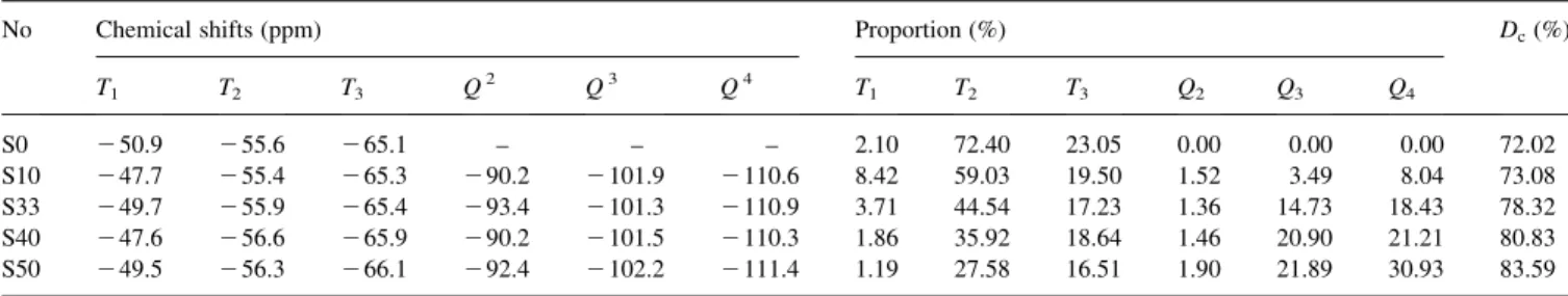
Fig. 3, which suggests the successful polymerization of the acrylic moiety in the hybrid S10.Fig. 4shows the29Si CP/ MAS NMR spectra of the prepared hybrid thin films, S0 – S50. The spectra show six peaks at 2 49.5 to 2 50.9, 2 55.4 to 2 56.6, 2 65.1 to 2 66.1, 2 90.2 to 2 93.4, 2 101.3 to 2 102.2, and 2 110.3 to 2 111.4 ppm, which are assigned to T1, T2, T3, Q2, Q3, and Q4, respectively. The positions of these peaks are similar to those reported in Refs. [25,26]. The splitting of the T2signal shown inFig. 4is interpreted by the spin – spin splitting of alkyl group. The proportion of the Ti, Qi, and Dcin the hybrid materials was determined by a quantitative analysis based on the peak areas of species, as listed in Table 2. The degree of condensation (Dc) of the hybrid materials was obtained from the proportions of Ti and Qiaccording to Eq. (2)[26]:
Dcð%Þ ¼ T1þ 2T2þ 3T3 3 þ Q1þ 2Q2þ 3Q3þ 4Q4 4 " # £ 100 ð2Þ
The proportion of Tispecies decreases with the increasing silica content in the prepared hybrid thin films but that of Qi and Dcspecies shows the opposite trend fromTable 2. The Qidepends on the Si – OH condensation of the silica. Hence, it is not surprising that it increases with increasing the silica
Fig. 2. FT-IR spectra of (a) pure colloidal silica, (b) colloidal silica-MSMA, (c) S10, (d) S33, and (e) S50 hybrid polymer films.
content. Similar explanation can be used for the cases of Ti and Dc.
3.2. Microstructure analysis
Fig. 5shows the TEM diagram of the colloidal MSMA/ silica solution for the case of S10. The image of TEM shows that the particle size of colloidal silica after hydrolysis/ condensation reaction is about 12 – 15 nm, which is approximate to the original size of the pure colloidal silica solution. Similar particle size of the colloidal silica was obtained for the cases of the S20 and S33. The result
suggests no further growth of silica particles for the case of the mole ratio of MSMA to colloidal silica higher than 22%. However, the coagulation of silica particles was observed and resulted in a large particle size of 25 – 30 nm for the case of S40 and S50. It suggests that the growth of silica particles by the Si – OH residue for the case of S40 and S50. The result indicates that the particle size of silica could be effectively controlled for the optimum ratio of MSMA to colloidal silica.
The size of the silica particle in the hybrid films was estimated from the SEM diagram. The size was about 20 nm
Fig. 4.29Si CPMAS NMR spectra of (a) S0, (b) S10, (c) S33, (d) S40 and (e)
S50. Fig. 5. TEM diagram of colloidal MSMA/silica for S10 (15 – 20 nm). Fig. 3.13C CPMAS NMR spectra of the hybrid S10 and pure colloidal silica.
for the cases of S10 – S33 and DT10– DT33. It increased to 25– 35 nm in the hybrid films of S40 – S50 and DT40 – DT50. The large size of the silica particle might be due to the incomplete coverage of silica particle surface and results in aggregation. This suggests that the size of the silica particle is basically different from the mole ratio of MSMA to colloidal silica. The moiety of acrylic polymer plays an important role in the film quality of the prepared hybrid materials.Fig. 6shows the SEM diagrams of prepared hybrid thin films for (a) DT50 and (b) S50. A uniform film is observed inFig. 6(a)but large pin-holes with the size of 120 –300 nm in the case ofFig. 6(b). The pin-holes shown inFig. 6(b)might be due to the large difference on the thermal expansion coefficient between the PMMA and silica. The moiety of the crosslinked polymer in the case of DT50 could reduce the thermal expansion coefficient and thus pin-holes in the films were prevented. Another possibility of the pin-holes shown inFig. 6(a)is due to the evaporation of solvent.
The shell thicknesses of the MSMA and MMA layers on the silica surface of the prepared hybrid films, S0 – S50, were estimated from the elemental analysis result. The average shell thickness decreases from 6.13 to 1.26 nm for MSMA layer and 3.07 to 1.01 nm for MMA layer, with increasing the silica content, respectively. The contents of the MSMA and MMA decrease from S0 to S50 and resulted in the trend of shell thickness in Table 3. The thin shell thickness of S40 and S50 supports the insufficient coverage of MSMA on silica particle suggested from the results of FTIR, TEM and SEM
Fig. 7shows the AFM image of the prepared hybrid thin film, DT10. The film thickness (h ), average roughness (Ra), and mean square roughness (Rq) of DT10 inFig. 7are 4630,
12.3, and 15.6 A˚ , respectively. The comparison of surface roughness with the film thickness is less than 0.1%, which suggests the excellent surface planarity of the prepared hybrid films. The film thickness and surface roughness of
Table 2
Chemical shift and relative proportions of Tiand Qispecies in the prepared hybrids, S0 – S50 obtained from the29Si CP/MAS NMR spectra
No Chemical shifts (ppm) Proportion (%) Dc(%)
T1 T2 T3 Q2 Q3 Q4 T1 T2 T3 Q2 Q3 Q4 S0 2 50.9 2 55.6 2 65.1 – – – 2.10 72.40 23.05 0.00 0.00 0.00 72.02 S10 2 47.7 2 55.4 2 65.3 2 90.2 2 101.9 2 110.6 8.42 59.03 19.50 1.52 3.49 8.04 73.08 S33 2 49.7 2 55.9 2 65.4 2 93.4 2 101.3 2 110.9 3.71 44.54 17.23 1.36 14.73 18.43 78.32 S40 2 47.6 2 56.6 2 65.9 2 90.2 2 101.5 2 110.3 1.86 35.92 18.64 1.46 20.90 21.21 80.83 S50 2 49.5 2 56.3 2 66.1 2 92.4 2 102.2 2 111.4 1.19 27.58 16.51 1.90 21.89 30.93 83.59
Fig. 6. SEM diagrams of the hybrid film, (a) DT50 (25 – 35 nm) and (b) S50 (25 – 35 nm).
Table 3
Element analysis of pure silica and the prepared hybrid materials, S10 – S50, and their corresponding layer thicknesses determined from the carbon content of elemental analysis
Sample C (%) H (%) N (%) DhMSMA a (nm) DhMMA a (nm) SiO2 1.42 1.22 0.06 – – S10 47.94 6.62 0.04 6.13 3.07 S33 34.20 4.30 0.04 2.22 1.54 S40 30.97 4.20 0.04 1.77 1.31 S50 25.47 3.27 0.04 1.26 1.01 a Dh
MSMAand DhMMAare the thickness of the MSMA and MMA layers
the prepared films are listed inTable 4. As shown inTable 4, the surface roughness increases with the silica content due to the growing particle size at high silica content. For the practical application, film thickness with a few mm might be necessary. As shown inTable 4, film thickness more than 3 mm could be obtained, which also had excellent surface planarity from the AFM study. This indicates the potential applications of the prepared hybrid films. The film thicknesses of the prepared hybrid films depend on the spin speed, solid content, and viscosity of the coating
solution. The solid content of the concentrated solution for the case of thick films is varied for the studied samples of S0 – S50 or DT0 – DT50. Hence, it might affect the film thickness of the prepared hybrid films. Hence, it is difficult to explain the trend of the film thickness with the silica content. However, the film thicknesses of the hybrid films with high silica contents, such as S40 – S50 and DT40 – DT50 are lower than others. It is probably due to the low acrylic monomer content or low degree of acrylic polymerization on the silica surface.
Fig. 7. AFM diagram of the hybrid film, DT10. The scan area is 5 mm £ 5 mm.
Table 4
Properties of the prepared materials
PMMA S0 S10 S20 S33 S40 S50 DT0 DT10 DT20 DT33 DT40 DT50 Td(8C) 230 290 298 297 302 306 315 376 381 382 384 385 386 Residuea(wt%) 3.18 16.43 27.78 36.75 45.20 52.30 62.09 14.69 21.44 26.63 27.99 49.66 56.47 Residueb(wt%) 0 9.67 18.69 27.73 39.47 45.79 54.83 5.37 14.81 24.28 36.58 43.21 52.67 hc(A˚ ) – 1190 1770 2130 2740 1440 1590 5920 4630 4520 3670 2180 1880 hd(A˚ ) 15190 15170 17860 15860 8832 9053 25070 34800 29000 28800 27300 25910 Rae(A˚ ) – 3.1 5.2 7.0 28.7 23.6 29.2 4.8 12.3 14.1 13.7 15.0 17.2 Rqe(A˚ ) – 4.1 8.4 10.2 38.4 29.9 36.8 6.0 15.6 18.0 17.4 19.0 21.7 n633 nmf 1.493 1.493 1.478 1.475 1.468 1.459 1.435 1.509 1.493 1.488 1.474 1.445 1.435 Hardnessg – HB 6H 6H 6H 4H 4H F 6H 6H 6H 6H 6H Hardnessh – 4H 9H 9H 9H 9H 6H 5H 9H 9H 9H 9H 9H a
Experimental results from TGA.
b
Theoretical values based on the assumption that only inorganic moieties are present at 900 8C.
c
Thickness of the prepared thin film.
d
Thickness of the prepared thick films by concentrating solution.
e
Raand Rqare the average and root mean square roughness of the prepared thin films, respectively. f
n is the refractive index of the prepared thin films.
g Hardness of the prepared thin film. h Hardness of the prepared thick film.
3.3. Thermal analysis
Fig. 8shows the TGA curves of PMMA, S10, and DT10. The order of the thermal decomposition temperature (Td) is DT10 . S10 . PMMA. This suggests the enhancement of thermal stability by incorporating silica moiety or the crosslinked acrylic polymer moiety. The thermal decompo-sition temperature (Td) of the prepared hybrid materials is shown inTable 4. The Tdof the S and DT hybrid materials is in the range of 290 – 315, and 376 – 386 8C, respectively. The higher Tdof the DT hybrid materials than the S is due to the crosslinked polymer structure of the DT. The increasing residue at 900 8C with increasing the silica content suggests the successful incorporation of the silica moiety in the hybrid materials. The higher experimental residue than the theoretical is probably due to the trapping of the polymer moiety in the silica. The black color of the polymer residues after the TGA runs also provides evidence that the organic moiety has been trapped in the inorganic matrix. Fig. 9
shows the DSC curves of PMMA, S10 and DT10 at heating rate of 10 8C/min under nitrogen flow. Only the PMMA shows a Tgat 125 8C among the three studied materials. The Tgis not existed in all of the prepared hybrid materials by DSC. It suggests the enhancement of thermal stability with incorporating the silica moiety. The thermal transition of the prepared hybrid materials was also studied by DMA and TMA and none of them showed a Tgin the studied materials.
3.4. Hardness analysis
The hardness of the prepared hybrid thin films was tested by a pencil test, as shown inTable 4. The hardness increases up to 6H (for the thin film case) or 9H (for the thick film case) with increasing the silica content for the case of the DT hybrid materials. It suggests the importance of incorporating the silica moiety on the mechanical proper-ties. For the case of S40 and S50, the hardness is less than
that of S10 – S30. It might be due to the pin-holes as observed by the SEM study.
3.5. Optical properties
Fig. 10 shows the dispersion of the refractive index (n ) and extinction coefficient (k ) of DT0 – DT50 in the wavelength range of 190 – 900 nm. The refractive index (n ) of the prepared hybrid thin films is listed inTable 4. As shown inTable 4, the n at 633 nm decreases from 1.509 of DT0 to 1.435 of DT50. It is because the smaller refractive index of pure silica than the acrylic polymer. The n could be linearly decreased with increasing the silica content, as shown in Fig. 11. The result suggests that the n of the prepared hybrid thin film could be tunable through the silica content. The n of the S hybrid materials also shows a similar trend inTable 4. The extinction coefficients (k ) of the films of the DT0 – DT50 are almost zero in the wavelength range of 190 – 900 nm, as shown in Fig. 10. The result suggests that the prepared hybrid thin films have an excellent optical transparency in the UV and visible region. According to the Rayleigh equation, the silica particle with a larger size
Fig. 8. TGA curves of PMMA, S10, and DT10 at a heating rate of 20 8C/min under nitrogen flow.
Fig. 9. DSC curves of (a) PMMA, (b) S10 and (c) DT10 at a heating rate of 10 8C/min under nitrogen flow.
Fig. 10. Variation of refractive index (n ) and extinction coefficient (k ) of the hybrid films DT0 – DT50 in the wavelength range of 190 – 900 nm.
(. 50 nm) results in a serious light scattering. The particle size of the prepared hybrid films is in the range of 20 – 35 nm. Therefore, significant scattering loss is avoided. This explains the results of optical transparence shown inFig. 10.
4. Conclusions
Hybrid thin films containing nano-size inorganic domain were prepared from poly(acrylic) and monodispersed colloidal silica with coupling agent. The experimental results showed the silica domain in the hybrid film was varied from 20 to 35 nm through the mole ratio of MSMA to colloidal silica. The prepared hybrid films from the crosslinked acrylic polymer moiety showed excellent sur-face planarity, good thermal stability, and hardness in comparison with the PMMA/silica hybrid films. The prepared hybrid films showed tunable refractive index with the silica fraction in the films. Excellent optical trans-parence was obtained in the prepared hybrid films. These results show that such hybrid thin films have potential applications as passive films for optical devices.
Acknowledgements
We thank the National Science Council and Industrial Development Bureau of Taiwan for the financial support of this work.
References
[1] Laine RM, Sanchez C, Brinker CJ, Giannelis E, editors. Organic/ inorganic hybrid materials, vol. 628. Warrendale, PA: Materials Research Society; 2000.
[2] Sanchez C, Lebeau B. MRS Bull 2001;26:377.
[3] Ogoshi T, Itoh H, Kim KM, Chujo Y. Macromolecules 2002;35:334. [4] Erashad-Langroudi A, Mai C, Vigier G, Vassoille R. J Appl Polym Sci
1997;65:2387.
[5] Wang B, Wilkes GL, Hedrick JC, Liptak SC, McGrath JE. Macromolecules 1991;24:3449.
[6] Chen WC, Lee SJ, Lee LH, Lin JL. J Mater Chem 1999;9:2999. [7] Lee LH, Chen WC. Chem Mater 2001;13:137.
[8] Chang CC, Chen WC. J Polym Sci, Polym Chem 2001;39:3419. [9] Philipp G, Schmidt H. J Non-Cryst Solids 1984;63:283.
[10] Kagan CR, Mitzi DB, Dimitrakopoulos CD. Science 1999;286:945. [11] Lee TW, Park OO, Yoon J, Kim JJ. Adv Mater 2001;3:211. [12] Huang WY, Ho SW, Kwei TK, Okamoto Y. Appl Phys Lett 2002;80:
1162.
[13] Tang J, Wang C, Wang Y, Sun J, Yang B. J Mater Chem 2001;11: 1370.
[14] Huynh WU, Dittmer JJ, Alivisatos AP. Science 2002;295:2425. [15] Yoshida M, Prasad PN. Chem Mater 1996;8:235.
[16] Xu CZ, Eldada L, Wu CJ, Norwood RA, Shacklette LW, Yardley JT, Wei Y. Chem Mater 1996;8:2701.
[17] Biteau J, Chaput F, Lahlil K, Boilot JP, Tsivgoulis GM, Lehn JM, Darracq B, Marois C, Levy Y. Chem Mater 1998;10:1945. [18] Coltrain BK, Landry CJT, O’Reilly JM, Chamberlain AM, Rakes GA,
Sedita JS, Kelts LW, Landry MR, Long VK. Chem Mater 1993;5: 1445.
[19] Sunkara HB, Jethmalani JM, Ford WT. Chem Mater 1994;6:362. [20] Jethmalani JM, Ford WT. Chem Mater 1996;8:2138.
[21] Chen WC, Lee SJ. Polym J 2000;32:67.
[22] Chan CK, Peng SL, Chu IM, Ni SC. Polymer 2001;42:4189. [23] Huang ZH, Qiu KY. Polymer 1997;38:521.
[24] Chan CK, Chu IM. Polymer 2001;42:6823.
[25] Joseph R, Zhang S, Ford WT. Macromolecules 1996;29:1305. [26] Chang TC, Wang YT, Chiu YS. J Polym Sci, Part A: Polym Chem
2000;38:1972.
[27] Jethmalani JM, Ford WT, Beaucage G. Langmuir 1997;13:3338. [28] Jethmalani JM, Sunkara HB, Ford WT, Willoughby SL, Ackerson BJ.
Langmuir 1997;13:2633. Fig. 11. Variation of refractive index with the silica content in the hybrid