國立交通大學
電子工程學系 電子研究所碩士班
碩 士 論 文
人體通道量測與雙耳助聽器通訊可行性研究
Measurement of Intra-body channels and feasibility study of binaural
communication for hearing-aids
研 究 生 : 游 旭 謙
指導老師 : 桑 梓 賢 教授
人體通道量測與雙耳助聽器通訊可行性研究
Measurement of Intra-body channels and feasibility study of binaural
communication for hearing-aids
研 究 生 : 游旭謙 Student : Shiu-chian You
指導教授 : 桑梓賢 教授 Advisor : Tzu-Hsien Sang
國 立 交 通 大 學
電子工程學系 電子研究所碩士班
碩 士 論 文
A Thesis
Submitted to Department of Electronics Engineering & Institute of Electronics College of Electrical and Computer Engineering
National Chiao Tung University In Partial Fulfillment of the Requirements
for the Degree of Master of Science
in
Electronics Engineering Sep 2011
Hsinchu, Taiwan, Republic of China
I
人體通道量測與雙耳助聽器通訊可行性研究
研究生:游旭謙 指導教授:桑梓賢 教授
國立交通大學
電子工程學系 電子研究所碩士班
摘要
在人體內部通訊系統(IBC)下,我們對靜電偶合和波導兩種傳輸方式做通道分 析,並探討其通道特性在雙耳助聽器通訊系統的可行性。首先先量測不同傳輸方 式下的通道狀況,之後收集使用者在不同的使用狀態下的通道資訊。由結果可分 析出人體通道的傳輸極限並設計最合式的傳送訊號波形降低功率消耗。我們的測 量結果可供在雙耳助聽器通訊傳送和接收端系統設計和傳送訊號的最佳化設 計。 關鍵字: 人體通道通訊、波導、雙耳助聽器、功率波形最佳化II
Measurement of Intra-body channels and feasibility
study of binaural communication for hearing-aids
Student:Shiu-chian You Advisor:Tzu-Hsien Sang
Department of Electronics Engineering & Institute of
Electronics National Chiao Tung University
ABSTRACT
In intra-body communication system, we analyzed the two types of intra-body communication channel: electrostatic type and waveguide type, and we investigated the feasibility of body channel characteristic for binaural hearing aids communication system. These studies will first measured the intra-body channel characteristics of different communication types, and conducted the analysis of different user states. From the result, we can get the information of the intra-body communication channel limitations, and design an optimal signal pulse that matches with Intra-body channel to lower the power consumption. The measurement result will make it better for the transmitter and receiver design of binaural hearing aids communication system, and transmitting power shape optimization.
III
Keywords — intra-body communication, waveguide, binaural hearing aids, power
IV
誌 謝
首先要感謝我的指導教授-桑梓賢老師,謝謝老師悉心的教導及討論,給了 我很多在研究方向的啟發,並在陷入研究困境時指引我正確的方向。使我在這些 年中獲益匪淺。再來要感謝我的口試委員丘增杰教授、張添烜教授,各位老師在 口試時讓我發現本論文主題不足和缺陷的地方,有了他們的建議,使這篇論文更 為完善。 再來要感謝眾位學長姐、同學、學弟妹的共同砥礪,在我還不熟悉量測儀器 的操作時能適時的提供意見。感謝欣德學長、正煌學長、宗達學長、哲聖學長、 譯賢學長,除了研究上的建議,還有實驗室生活的點點滴滴,讓我能繼續堅持下 去。也感謝一起努力的俊育同學、耀賢同學們的陪伴。當然也不能忘記實驗室的 建志學弟、建宏學弟、胤宏學弟、碩文學弟、柔綾學妹們陪我度過這個充實的研 究所生活,感謝大家。 游旭謙 謹誌 2011年9月V
Contents
中文摘要 ... I 英文摘要 ... II 誌謝... IV 目錄... V 圖目錄 ... VI Chapter 1 ... 1 Introduction ... 1
1.1 Introduction Intra-body communication system ... 2
1.2 Motivation and Contributions ... 3
Chapter 2 ... 4
Analysis of intra-body channels ... 4
2.1 Introduction of types of intra-body communication channels ... 4
2.2 Electrostatic coupling type / waveguide ... 5
Chapter 3 ... 8
Measurement and feasibility study of intra-body channels ... 8
3.1 Measurement ... 8
3.1.1 Experimental setups ... 9
3.2 Remarks on the measurement procedure ... 11
3.3 Measurement Results and Analysis ... 13
Chapter 4 ... 18
Pulse Shape Optimization ... 18
4.1 Backgrounds ... 18
4.2 Maximization of Signal Peaks ... 19
4.3 Maximization of Transfer Power ... 22
4.4 S-Parameters ... 24
Chapter 5 ... 26
Summary and Future work ... 26
VI
List of Figures
Fig.1.1 Block diagram of Intra-body system. ... 3 Fig.2.1 Three type of data transmission through the IBC channel. [3] ... 5 Fig 2.2 Characteristics result of human body channel in [4] (a) in the time
domain (b) in the frequency domain. ... 6 Fig 2.3 Intra-body channel frequency response result for waveguide type [3] ... 7 Fig 2.4 Comparison of human body impedance for different kinds of electrodes. 7 Fig 3.1 Simple communication channel model of IBC... 9 Fig 3.2 Experimental setup for the body channel measurement (a)
sweep-frequency by network analyzer (b) time-domain experimental
configuration ... 10 Fig 3.3 Actual Experimental setup for body channel measurement. (a) Electrodes placed on arm. (b) Electrodes placed inside ears. ... 11 Fig 3.4 Interference of 60Hz AC source (Input is 1MHz sine wave) ... 12 Fig 3.5 Frequency response of IBC channel on arm: (a)Change Tx/Rx distance: 15/ 30/ 40/ 120cm. (b) Change Electrode pair distance: 1/2/4 cm ... 14 Fig 3.6 Frequency response of IBC channel on Head: (a) Change electrode
Material: Ag-CL/silver (b) Change user using state ... 16 Fig 3.7 Signal simulation for transmit 2Mbits PRBS signal through body channel. ... 17 Fig 4.1 Intra-body channel model... 20 Fig. 4.2 (a) Impulse response of IBC head channel. (b) The input pulse shape matched to IBC head channel V ti( ) ... 21
Fig 4.3 the rectangular wave pulse shapes width matched the width of the main positive peak of the channel impulse response. ... 21 Fig 4.4 The IBC channel model of transmitter ... 22 Fig. 4.5. A designed minimum-phase pulse shape which occupies the lowest 15% frequency band. ... 24 Fig 4.6 2-port Network ... 25
1
Chapter 1
Introduction
Today, there are many electronic devices used in our daily life, such as cellular phones, portable computers, MP3 players, medical sensors etc. They usually have or are evolving to have communication capability with each other through wire or wireless means.
Intra-body communication (IBC) is a signal communication technology in the area of personal area networks (PANs) [1]. A Personal area network is a network used for communication among different electronic devices around a human body, usually using wireless communication, such as Infrared and Bluetooth. Because infrared and Bluetooth send signals through the air, they are prone to be affected by air channels, which cause severe signal attenuation and distortion. These shortcomings usually are overcome by increasing transmitting signal power. However, large signal power is not desirable, especially with small portable devised, such as hearing aids. People expect hearing aids, which are battery-powered, to last at least one week between regular battery changes. Therefore, to find a low-power alternative to Bluetooth and infrared for communication purpose become a crucial issue in developing binaural hearing
2
aids. Intra-body communication that uses human body to transmit signals is such a promising alternative. The human body, in particular, the skin surface, is used as the conductor. Because signals do not leak out of the skin, signal attenuation is relatively smaller than that seen in other wireless radio techniques.
In modern binaural Hearing aids, they are smaller, more flexible and better enabled to deal with background noise. In order to deal with background noise, they have advanced algorithms that need to exchange information with each other. Therefore, the battery durability becomes a very important issue in binaural hearing aids. There are some advantages for using Intra-body communication. One is low power consumption compared to wireless radio techniques. For example, in Bluetooth, the power consumption can be as large as 350mW [2]. In some IBC reports, the power consumption can be as low as 30mW [8], some even down to 0.2mW [4]. With the human skin as the conductor, there is no need to use wires connecting hearing aids, and therefore the weight of equipment is reduced and users can feel more comfortable. And when users wear Complete-In-Canal (CIC) hearing-aids, the ear modules contact with skin with good attachment. Therefore, we can more easily make the electrodes that are in contact with skin when worn on.
1.1 Introduction intra-body communication system
The block diagram of an example Intra-body communication system is shown in Fig 1.1. It has a digital signal processor (DSP), amplifier drivers, and electrodes in both transmitter and receiver. Signal will be processed by transmitter and sending through the electrode and human body. Human body becomes a conductor to send
3
signal to receiver. Because the signal transmission medium is no longer a general wire, but will change the state of motion of the human body. That is why channel analysis becomes so important.
Fig.1.1 Block diagram of Intra-body system.
1.2 Motivation and Contributions
The current study of intra-body communication is divided into two categories, one is the electrostatic coupling (ESC) type and the other is waveguide type. That will be explained in Chapter 2. No matter which type method to use, these studies will first analyze the body channel characteristics, and then design a device to verify the result. However, there is a lack of comprehensive analysis for intra-body channels. In this study, we investigated the common characteristic limitations of both types of body channels, and conducted the analysis of different user states which has not been examined. The information will make it better for the devise design, and it also can design an optimal signal pulse that matches with Intra-body channel to lower the power consumption. We also measured the channel characteristics of head for hearing aids, and we want to utilize the results toward the communication of hearing aids for the future. Optimization of pulse shape is also investigated for the attempt to further reduce power consumption. An itemized list of contributions is provided in Chapter 5.
4
Chapter 2
Analysis of intra-body channels
2.1 Introduction of types of intra-body
communication channels
According to the different ways of data transmission, Intra-body communication system has three types shown in Fig.2.1: the simple circuit, electrostatic coupling, and waveguide [3]. In the simple circuit type, input and output grounds must be connected with a wire. In the electrostatic coupling type, it transmits signal by creating an electric field between the input/output devices through the human body and the surrounding environment. This type was used in [1]. In the waveguide type, input and output device each has a differential pair of electrodes, and the electromagnetic wave is sent through the body channel, i.e., the human body is treated as a waveguide.
In recent years, many studies usually focus on two types: electrostatic coupling and waveguide. These methods have better performance, especially in power consumption, than RF wireless technologies. They have high bit rates and big bandwidth, and the power can be even down to 0.2-mW [4]. In some earlier ECG studies, the carrier frequency and bandwidth is limited to less than 100 kHz due to the body transmission characteristics [5]. Now the bandwidth is able to reach 100MHz [4].
5
However, a completely detailed analysis of channel characterization and comparison still has not been completed.
Fig.2.1 Three type of data transmission through the IBC channel. [3]
2.2 Electrostatic coupling type / waveguide
For method of electrostatic coupling type, that originated from the research of T.G. Zimmerman in 1996 [1]. Most important feature of this method is used only single electrode, and return path is provided by the “earth ground” which is electric field from surrounding environment. Resulting in a maximum channel capacity of 417 kilobits and bandwidth of 400kHz at the time [1]. Recently, a low-power and high speed human body communication digital transceiver based on wideband signaling was developed [4]. The transmission characteristics of intra-body channel have been investigated by sinusoidal waves with 1Vp-p and from 100Hz to 1GHz [4]. But there is a serious problem in the measurement of electrostatic coupling type: “ground free
6
system”. That means the transmitter and receiver have to connect with different power sources because instruments of power sources were the same in measurement. So they used a battery-power transmitter and a oscilloscope made the transmitter and receiver have different ground to solve this problem. The bandwidth has about 100MHz and -6dB attenuation in Fig 2.2 .
Fig 2.2 Characteristics result of human body channel in [4] (a) in the time domain (b) in the frequency domain.
Because electrostatic coupling type transmission quality depend on the surrounding environment. Consequently, some researcher began to study for waveguide type of intra-body communication. In the study, they investigated the channel characteristics of waveguide type and human body impedance for different kinds of electrodes [3]. Two pairs of electrodes were attached with paste to the wrist and they used function generator generated 1Vp-p sine wave from 0.5 to 50MHz. Fig 2.3 is shown the result demonstrated voltage linearity for body channel with different voltage of input signal. Fig 2.4 is the measurement result of different material electrode that impedance fluctuation was limited to within 10% and no drastic fluctuations [3].
7
Fig 2.3 Intra-body channel frequency response result for waveguide type [3]
8
Chapter 3
Measurement and feasibility study
of intra-body channels
3.1 Measurement
In this section, we will describe the experimental setup of the measurement platform. We want to get the information to analysis channel status from intra-body channel frequency responses. And identify the factors that cause signal attenuation and induce noise. Search a feasible channel in the worst conditions to reduce the impact to the communication quality. Fig 3.1 shows a simplified communication channel model. X(t) is the input signal, H(t) represents the body channel response, and
N is noise experienced during transmission. Then output signal Y(t) can be expressed
as:
(1) Because the noise is independent on channel state, we can reduce its impact on channel estimation by accumulating longer data. The channel frequency response H(f)
( ) ( ) ( )
9
can be obtained by transforming signals to the frequency domain through the following equation:
(2)
Fig 3.1 Simple communication channel model of IBC
3.1.1 Experimental setups
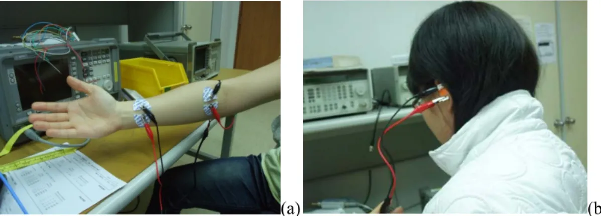
We chose the waveguide type shown in Fig 3.2(a) to investigate, mostly due to technical difficulties associated with the electrostatic coupling type. In the first part of measurement, two pairs of electrodes are attached to the arm. The input port (port1) connected to the wrist and output port (port2) connected to the upper arm. In the second part of the measurement, we focus on the channel around human head. To be specific, we are interested in the channel between two pairs of electrodes placed inside both ears. Fig 3.3(b) is shown the actual measurement of silver electrodes placed inside ears with earplug.
The method we used to obtain the frequency response of IBC channel is called the sweep stimulus method. The input sweep signal is obtained from a network analyzer (R&S® ZVL13). Input signals were generated sweep 1Vp-p (peak-to-peak) sine
( ) ( ) ( ) Y f H f X f =
10
wave of the frequencies form 50KHz to 25MHz by Network analyzer port 1. Output signals were measured from port2. In Fig 3.2(b), input signals were generated by function generator (Agilent 33250A F/A).Consisted of 1Vp-p (peak-to peak) sine wave from 100Hz to 25MHz. Output signals were detected by digital oscilloscope (Agilent MSO54832D). Then signal attenuation of the IBC channel was measured form I/O gain.
(a)
(b) Fig 3.2 Experimental setup for the body channel measurement (a) sweep-frequency by network analyzer (b) time-domain experimental configuration
11
(a) (b)
Fig 3.3 Actual Experimental setup for body channel measurement. (a) Electrodes placed on arm. (b) Electrodes placed inside ears.
3.2 Remarks on the measurement procedure
A careful setup is required to measure the body channel characteristics because many factors must be considered, for example, the ground plane [7]. In order to reduce the alternating current that produces the 60Hz interference, the instruments must be connected to the same AC power source. Because Tx & Rx (I/O) are in different ground plane. Fig 3.4 shows the 60Hz AC interference, left side is the output has been disturbed DC offset caused by the alternating current, and the right side shows the correct signal we sent.
Time(s) Vo lt ag e (V ) Time(s) Vo lt ag e (V )
12
Fig 3.4 Interference of 60Hz AC source (Input is 1MHz sine wave)
Input impedance of instrument is often overlooked in measurements like this. The input impedance of the network analyzer is 50Ω but that of the oscilloscope is approaching infinity (Usually 10MΩ). So in the measurement as in Fig 3.2(b), the output side should be added a 50Ω load such that the result is correct. In addition, the current should be limited to 700uA at 1MHz, which meets by International Commission on Non-Ionizing Radiation Protection (ICNIRP)[6].
13
3.3 Measurement results and analysis
In order to compare the attenuation of IBC channels under different states, We designed different variables to the measurement for the part of arm and head. In the experimental part of arm, we change the Input/Output length and the electrode pair distance.
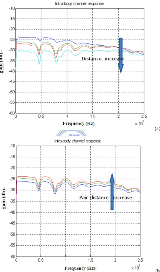
Fig. 3.5(a) shows intra-body channel response change by increasing I/O distance on arm. We can find the attenuation increase when distance increase from 15cm to 120cm, the transmission’s gain though the human body is more than -30dB at I/O distance 40cm (red line) from 100kHz to 20MHz. In the worst case: 120cm I/O distance still has -32dB gain. Signal attenuation increase with distance is to be expected.
Fig. 3.5(b) shows signal attenuation become lower (about 3dB) by increasing electrode pair distance from 1cm to 4cm. Because increasing the differential pair can reduce the signal reflection from the same port. Obviously, body channel response becomes worse at high frequency, and signal is difficult to pass the intra-body channel at low frequency lower than 100 kHz. The results show that human body channel as a band-pass filter.
Fig 3.5 F 15/ Frequency re 30/ 40/ 120 esponse of I 0cm. (b) Cha 14 IBC channe ange Electr el on arm: (a ode pair dis
a)Change T stance: 1/2/4 Tx/Rx distan 4 cm (a) (b) nce:
earp perf Ag-mea i( db ) Fig. 3.6(a plugs) that formance w -AgCl. And asurement. 0 -40 -35 -30 -25 -20 -15 -10 Me g ga in (d b) a) is the intr compare th was improv d earplug t 1 2 ra-body cha he material ved about 5 type has do 3 4 Intra-bo F 15 annel respon of Ag-AgC 5dB becaus own 10 to 4 5 frequency ody channel re Frequency (Hz) nse on head Cl electrode se silver ha 5 db loss 6 7 esponse d (we set th e and silver as better c s compared 8 9 he electrode r electrode. onductivity d to arm b 10 x 106 es on The y the ased (a)
situ con touc typi also The surf wor Fig 3.6 Fig 3.6 (b ations; for dition. We ch the cond ical silver e o down a fu e signal los face. In add rse. 0 -60 -55 -50 -45 -40 -35 -30 -25 -20 -15 -10 Me g gai n ( db ) 6 Frequency Material b) shows th example, hu found that t ductive path arplug mea urther 2~3dB ss increases dition, if the 0.5 y response o l: Ag-CL/sil he plot of uman conta the channel h; the atten asurement. I B, compared s because s e person has 1 Intra-bo Fr 16 of IBC chan lver (b) Cha IBC chann act with the
l response c nuation only If the user is d to the typ sweat can i s higher bod frequency ody channel re requency (Hz) nnel on Hea ange user us nel respons conductive curve almos y decreases s in the swe pical silver e increase the dy-fat rate, 1.5 esponse
ad: (a) Chan sing state e by chang e path or us st remain th s 1~2dB, co eating condi earplug type e conductiv the body ch 2 nge electrod ging user u sers in swea he same if u ompared to ition, the lo e measurem vity of the hannel beco 2.5 x 10⁷ (b) e using ating users o the oss is ment. skin omes
17
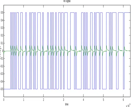
Fig. 3.7 is the simulation in which we transmit a 7-bits pseudo random binary sequence though the intra-body channel. We set the input signal amplitude to 1Vp-p with I/O apart of 30cm on the arm. The green curve is the received signal, and it is a narrow small pulse that comprises positive and negative maximum around 76mVp-p because human body is a band-pass channel. For our design detection circuit Schmitt trigger can reconstruct the signal even if it is lower than 50mVp-p. It shows that we can reduce transmission signal amplitude to make power consumption lower. Now power consumption is 64uW for our detection circuit model.
Fig 3.7 Signal simulation for transmit 2Mbits PRBS signal through body channel. 0 1 2 3 4 5 6 x 10⁻⁵ -0.5 -0.4 -0.3 -0.2 -0.1 0 0.1 0.2 0.3 0.4 0.5 time v ol tage Rx signal
18
Chapter 4
Pulse shape optimization
4.1 Backgrounds
In binaural hearing aids, power consumption of signal exchange of both sides is an important issue. When the transmitter sends signals through Intra-body channel, there will be a great loss (15~20dB) on the signal. One way to maintain healthy signal-to-noise ratio at the receiver side is to increase the transmitter power. However, this contradicts our mission of designing an ultra low-power hearing aid. Another way to mitigate the problem of excessive signal attenuation is to design an appropriate signal pulse shape that matches with Intra-body channel so that the signal attenuation may be minimized.
We have come up with two general approaches to the pulse shaping problem. The first is to assume that the transfer function (or the S21 parameter) of the body
channel is at least partly known. In this case, the received signal may be represented by the transmitting signal through the channel effect. It is therefore possible to design the optimal transmitting pulse shape by considering its effects on the received signal. The second approach does not require the knowledge of the transfer function; rather we assume that the transmitter has the knowledge of the channel impedance.
19
And the transmitter would try to “pump” as much power as possible into the channel. Even though by pumping into as much power as possible does not have any guarantee on the quality of the received signal on the other side, it is intuitive that at least it won’t hurt to increase the into power transferred into the body channel.
The above two approaches in fact have a serious drawback; namely, they fail to take into consideration the fact that the body channel itself may vary dramatically for different situations and change fast when affected by the external environment. When the body channel changes huge and fast, it will be extremely difficult to optimally design the transmitting pulse shape adaptively for every situation and each instance. Therefore, our primary goal is to establish a robust optimal design procedure which fully considers the possible variations of channel conditions and design a robust pulse shape which can manage to perform under hugely varying conditions. However, our goal has not been materialized at this moment. We have made plans for future works and the robust optimal pulse shaping is one of the directions that we will continue to pursue.
In the following, we will discuss about the two afore-mentioned approaches separately.
4.2 Maximization of signal peaks
To reduce the power consumption, we try to find an input signal shape that can make the signal at the receiver side go to the maximum. The intra-body channel model is shown in Fig. 4.1. V ti( ) is the transmitting signal in time domain, and
( )
o
V t is the receiving signal in time domain. S21 is the intra-body channel response.
Output signal V to( ) can be write as:
(4.1)
21
( ) ( ) ( ) ( )
o i
20
where S21( )t represents the channel impulse response obtained by inverse Fourier
transforming the S21 parameter to the time domain (more details of it are discussed in
Section 4.4). N t( ) is the noise, but in our attempt, we will not further consider the effects of noise. Intuitively we try to get the maximum output voltage V to( ) through
optimizing the pulse shape of the transmitting signal V ti( ). However, there must be
some constraints on the transmitting signal, otherwise the unconstrained design will lead to a unbounded transmitting signal. Here, we consider two possibilities of choosing constraints:
Fig 4.1 Intra-body channel model
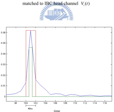
1. If we constrain the power (L2 norm) of the input pulse, then the shape should match the time-reversed impulse response of the channel. That is like a matched filter problem. The matched filter is the optimal linear filter for maximizing the signal to noise ratio in the presence of additive stochastic noise. Though we most often express filters as the impulse response of convolution systems, it is easiest to think of the matched filter in the context of the inner product such that we maximize the peak of
( )
o
V t , and the shape V ti( ) is the time-reversed impulse response of IBC channel as
shown in Fig. 4.2.
2. If we constrain the pulse shape to be a monopole rectangular shape, and further restrict the maximum value of the input pulse (L_inf norm), and we want to
Tx
Rx
Vi(t)
+ ‐S
21S
12Vo(t)
+ ‐Intra‐body channel
H(t)
21
mitigate the possibility of diminishing the output peak if the channel changes, then the pulse should be a rectangular wave whose width is about the width of the main positive peak of the channel impulse response.
(a) (b)
Fig. 4.2 (a) Impulse response of IBC head channel. (b) The input pulse shape matched to IBC head channel V ti( )
Fig 4.3 the rectangular wave pulse shapes width matched the width of the main positive peak of the channel impulse response.
40 60 80 100 120 140 160 0 0.01 0.02 0.03 0.04 0.05 0.06 40 60 80 100 120 140 160 180 200 0 0.01 0.02 0.03 0.04 0.05 0.06 time
22
4.3 Maximization of transfer power
In this section, we try to optimize the input pulse shape by maximizing the power transferred into the IBC. From the Fig. 4.4, transmit power can be written as:
∑
⎭ ⎬ ⎫ ⎩ ⎨ ⎧ = k in i k Z k V P ) ( | ) ( | Re 2 (4.2)in which Vi(k) is the input voltage signal in the frequency domain, Zin is the input impedance of the IBC, and k is the frequency index. We replace | | with Xk and Zin is a complex vector. The equation 4.2 can be rewrite as:
(4.3) H(t) Body channel Input signal Vi Zin Tx Fig 4.4 The IBC channel model of transmitter
Then we proceed to maximize the transfer power P subject to constraints imposed on the input signal. The first constraint is to limit the total power, that is,
∑
Xk . Besides the total power constraint, we need another constraint in the frequency domain. Note that if there is no limiting constraint in the frequency domain, the transmitting power will concentrate on a single frequency where the channel condition is the most favorable. In order to allocate the power over a broader2 2 Re k k k k k k k k k X P a jb a X a b ⎧ ⎫ = ⎨ ⎬ + ⎩ ⎭ = +
∑
∑
23
frequency range, a limiting power mask should be put into place. A naïve choice of mask would be a regular flat limitation on all frequencies, that is, we limit the input
power Xk for each k. The coefficient
2 2
k k k
a
a +b just like a system gain, so we
simplified it to gk . The overall problem formulation becomes:
C C P X X g k total k k k ≤ ≤
∑
∑
subject to maximize k kEven with the limiting power mask, we can recognize that the maximization of transfer power will lead to the concentration of transmitting power on the favorable frequency band. In the case of head IBC, the favorable frequency band is the low-pass band. Therefore, the optimal transfer power strategy would be to concentrate power at the low frequency band.
Next, after solving the power allocation issue, we need to give the power allocation plan a proper phase term in order to generate a proper time-domain pulse shape which also conforms to the power allocation plan. And from the result of maximizing P , we will get the input power shape by equation (4.4):
k j k opt i k X e V( )= , φ (4.4)
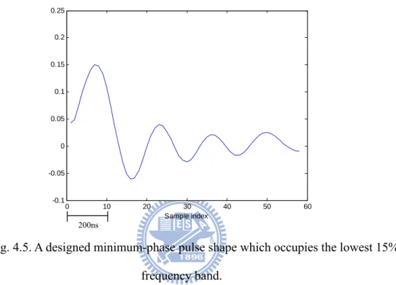
where φk is the phase term we assign to the input signal power plan. Here we choose to give the plan a minimum-phase function [11] such that the pulse shape in time domain can be kept as short as possible. A shorter pulse means greater tolerance of inter-symbol interference when the transmission speed increases.
In the following, we give a numerical example of such a minimum-phase pulse which also occupies the lowest 15% of the frequency band defined by half of the sampling rate. As can be seen, the pulse shape might be too arbitrary and
24
hard-to-generate with today’s mixed-signal circuit. In the future, we hope to learn more insights from this optimization procedure and come up with more practical suggestions.
Fig. 4.5. A designed minimum-phase pulse shape which occupies the lowest 15% frequency band.
4.4 S-Parameters
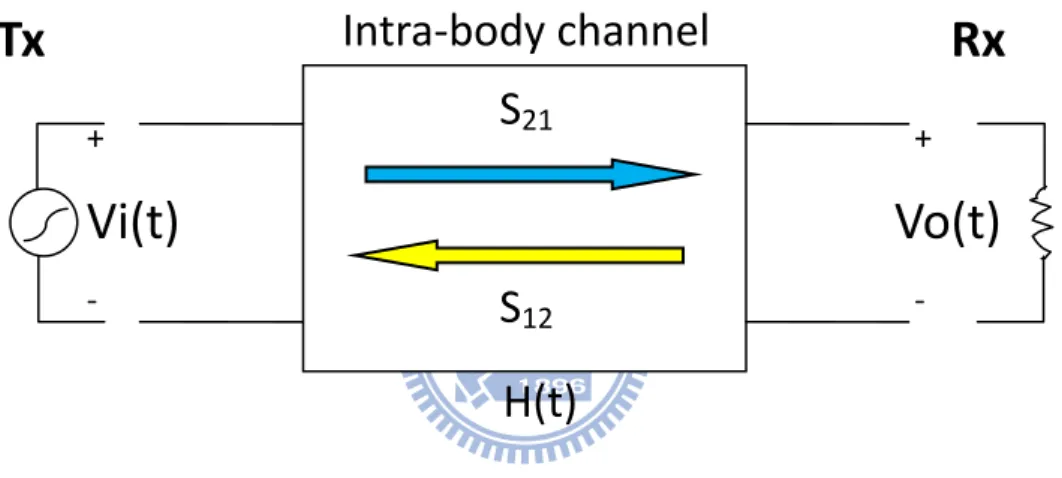
S-parameters are the basic measured quantities of a network analyzer. They describe how to modifie a signal that is transmitted or reflected in forward or reverse direction [9]. For a 2-port measurement the signal flow is as fig. 4.4.
0 10 20 30 40 50 60 -0.1 -0.05 0 0.05 0.1 0.15 0.2 0.25 Sample index 200ns
25 11 12 21 22 Vi S S Vi Vo S S Vo − + + − ⎡ ⎤ ⎡ ⎤ ⎡ ⎤ = × ⎢ ⎥ ⎢ ⎥ ⎢ ⎥ ⎣ ⎦ ⎣ ⎦ ⎣ ⎦
Fig 4.6 2-port Network
In the 2-port network, I/O signal can be expressed with the following matrix:
(4.8)
The equation shows that S-parameters are expressed as S<out><in> ,where <out> and
<in> is the output and input port of Network analyzer. Output port signal is defined Vo, and the input port is Vi.
z S11 is the input reflection coefficient, defined as the ratio of the wave
quantities Vi- / Vi+, measured at PORT 1 (forward measurement with
matched output and Vo- =0).
z S21 is the forward transmission coefficient, defined as the ratio of the wave
quantities Vo+ / Vi+ (forward measurement with matched output and Vo- =
0).
z S12 is the reverse transmission coefficient, defined as the ratio of the wave
quantities Vi- / Vo- .
z S22 is the output reflection coefficient, defined as the ratio of the wave
quantities Vo+ to Vo- . [10].
S
22Port1
Port2
Vi
+Vi
‐Vo
+Vo
‐S
21S
12S
1126
Chapter 5
Summary and future work
We analyze the different characteristics of two kinds of intra-body channels: the electrostatic coupling type and waveguide type. We describe the experimental setup of the measurement platform to get the information to analyze channels. Furthermore, we identify the factors that cause signal attenuation and induce noise. We establish the feasibility of utilizing the intra-body channel, especially the waveguide type, even with the worst condition in our measurement set-up, to successfully transmit digital data up to 2 Mbps without severe impact from channel effect and noise onto the signal quality.
And then we do an optimization design of the input pulse shape from the averaged measurement of IBC channel information. In the future, we will develop robust optimization design to find the feasible pulse shape to take into account of variability of IBC channels for our ultra low-power hearing aid design.
In summary, we did in this study:
z Analysis the intra-body communication channels including electrostatic coupling type and waveguide type.
z Measure the intra-body channel response with different factors, especially the head channel with varying user status.
z Feasibility study of intra-body channel for transmitting up to 2 Mbps for ultra low-power hearing aid design.
27
z Use two formulations to optimize the input pulse shape: (1.maximization of Signal Peaks. 2. maximization of transfer power) for low power design from IBC channel information.
28
Bibliography
[1] T.G. Zimmerman, ”Personal Area Networks: Near-field intrabody communication”, IBM Systems Journal, 1996
[2] Alexandre L, Javier Del Prado Pav6'n, Jo Degraer, Jacky Talayssat, and Gilles Jacquemodt, ”Power Consumption Analysis of a Bluetooth over Ultra WVide Band System”.
[3] Keisuke Hachisuka, Azusa Nakata, Teruhito Takeda, Yusuke terauchi, Kenji Shiba, Ken Sasaki, Hiroshi Hosaka, and Kiyoshi Itao, ”Development and
performance analysis of an intra-body communication device”, 12th International conference on Solid State Sensors, Actuators and Microsystems, Boston, June. 2003
[4] Seong-jun Song, Namjun Cho, Hoi-Jun Yoo, ”A 0.2-mW 2Mb/s digital transceiver based on wide band signaling for human body communication”,
IEEE journal of solid-state circuit, SEP 2007
[5] Takashi Handa, Shuichi Shoji, Shinichi Ike, Sunao Takeda, Tetsushi
Sekiguchi, ”A very low-power consumption wireless ECG monitoring system using body as a signal transmission medium”, International Conference on Solid
State Sensors, June 1997
29
for limiting exposure to time-varying electric, magnetic, and electromagnetic fields (up to 300 GHz)”, Health Phys. 74 (1998).
[7] Namjou C, Jerakd Y, Seong-Jun S, Jeabin L, Seonghyun J Hoi-Jun Y, “The human body characteristics as a signal transmission medium for intra-body communication”, IEEE transaction on microwave theory and technique, MAY 2007.
[8] Chang hee H, Jin bong S, Jung Hwan H, Jin Kyung K, Duck Fun P, Sung Weon K, ”A novel system for intrabody communication: Touch-and-play”, Proc. ISCAS 2006.
[9] R&S®ZVL Vector Network Analyzer Operating Manual
[10] J. David Irwin, R. Mark Nelms ,”Basic engineering circuit analysis,9th edition”, WILEY, 2008 .
[11] Alan V. Oppenheim, Ronald W. Schafer, ”Discrete signal processing 3rd ed”, Pearson, 2010.
![Fig 2.2 Characteristics result of human body channel in [4] (a) in the time domain (b) in the frequency domain](https://thumb-ap.123doks.com/thumbv2/9libinfo/8099527.165095/14.892.158.760.344.729/fig-characteristics-result-human-channel-domain-frequency-domain.webp)
![Fig 2.3 Intra-body channel frequency response result for waveguide type [3]](https://thumb-ap.123doks.com/thumbv2/9libinfo/8099527.165095/15.892.272.644.122.416/fig-intra-body-channel-frequency-response-result-waveguide.webp)