國
立
交
通
大
學
資訊學院 資訊學程
碩
士
論
文
以 SIP 為基礎並輔以 Push 機制的 VoIP 行動無線
通訊網路之設計與實作
Design and Implementation of A SIP-Based Vehicular Wireless
Network for VoIP Services with Push Mechanism
研 究 生:程幼棣
指導教授:曾煜棋 教授
以 SIP 為基礎並輔以 Push 機制的 VoIP 行動無線通訊網路
之設計與實作
Design and Implementation of A SIP-Based Vehicular Wireless
Network for VoIP Services with Push Mechanism
研 究 生:程幼棣 Student:Yu-Li Cheng
指導教授:曾煜棋 Advisor:Yu-Chee Tseng
國 立 交 通 大 學
資訊學院 資訊學程
碩 士 論 文
A ThesisSubmitted to College of Computer Science National Chiao Tung University in partial Fulfillment of the Requirements
for the Degree of Master of Science
in
Computer Science June 2007
Hsinchu, Taiwan, Republic of China
以 SIP 為基礎並輔以 Push 機制的 VoIP 行動無線通訊網路
之設計與實作
學生:程幼棣
指導教授
:曾煜棋 教授
國 立 交 通 大 學 資 訊 學 院 資 訊 學 程 碩 士 班
摘
要
由於可攜式裝置越來越普及,所以如何讓這些行動裝置隨時隨地
皆可連上網路變成重要的課題。文中,我們開發一個以 SIP 為基礎並
整合 MANET(Mobile Ad-Hoc Network)及行動網路的架構,實作行動
網路與 VoIP(Voice over IP)服務。我們提出車上行動用戶可自成一
MANET 網路並透過一個配備兩網路介面的 SIP 行動網路閘道(SIP
Mobile Network Gateway, SIP-MNG)來上網與打網路電話。然而當系
統一旦啟始,因為 SIP-MNG 對外利用行動介面撥接、連結網際網路,
而且必須一直保持對外的通訊,所以對系統而言無論在電力和價格上
都是個負擔,開得越久,網路存取費用收得越多,電力也消耗越快。
考慮到語音服務的需求並非一直存在,我們提出一個 push 機制,使
得語音服務不存在的時候,SIP-MNG 可以關掉對外的介面,只有當
語音服務的需求發生時,才透過 push 機制“wake up"SIP-MNG 上的
對外介面,保證系統不會遺失任何語音通話,同時達到省電與節費的
要求。文中並且包含我們系統的實作成果。這個系統具有架設簡單、
結構彈性的優點,並提供使用者具移動性、彈性、以及服務無間隙功
能的語音服務。
關鍵詞: MANET(Mobile Ad-Hoc Network), VoIP(Voice over IP),
SIP(Session Initiation Protocol), push mechanism,
Design and Implementation of A SIP-Based Vehicular Wireless
Network for VoIP Services with Push Mechanism
student:Yu-Li Cheng
Advisors:Prof. Yu-Chee Tseng
Degree Program of Computer Science
National Chiao Tung University
ABSTRACT
As portable devices are gaining more popularity, maintaining Internet connectivity anytime and any where becomes critical, especially for mobile and vehicular networks. Network mobility (NEMO) and IP mobility are gaining more and more importance. In this work, we develop a SIP-based mobile network architecture to support network mobility for vehicular applications. We propose to form a mobile ad-hoc network (MANET) by the mobile hosts (MHs) inside a vehicle or a cluster of vehicles. The MANET is connected to the outside world via a SIP-based Mobile Network Gateway (SIP-MNG), which is equipped with one or multiple external wireless interfaces and some internal IEEE 802.11 interfaces. The external interfaces of the SIP-MNG are to support Internet connectivity by aggregating users' traffics to and from the Internet. In addition, exploiting session information carried by SIP signaling, the SIP-MNG supports resource management (RM) and call admission control (CAC) for the MHs. Wireless access, however, incurs charges, power consumption, and overheads of mobility management. So, it is desirable to allow the SIP-MNG to disconnect its external interfaces when necessary. To guarantee that users inside the mobile network will not lose any incoming request, we propose a push mechanism through short message services (SMS) to wake up these wireless interfaces in an on-demand manner. We show the detail signaling to support such mechanism. The proposed system is fully compatible with existing SIP standards. Our real prototyping experience and some experimental results are also reported.
Index Terms: MANET (Mobile Ad-Hoc Network), mobile computing, NEMO
(Network Mobility), push mechanism, SIP (Session Initiation Protocol), wireless network.
Acknowledgements
My advisor, prof. Yu-Chee Tseng, is the first one I would like to express my gratitude to. With the wonderful research conditions he provided and his attentive instructions, I came to discover the pleasure of research. I am also grateful my senior. Jen-Jee Chen. Without his help and suggestions, I would not be able to have this thesis done. Finally, I would like to thank all HSCC members for their generous advises. Discussing with them benefited me in many ways.
Lastly, I give my wholehearted gratitude to my family, especially my wife, for all the love, care and inspiration she has always given me.
Contents
中文摘要. . . .i
Abstract . . . .ii
Acknowledgments. . . .iii
Contents. . . .iv
List of Figures . . . .vi
List of Tables . . . .vii
1 Introduction . . . .1
2 Related Work . . . .7
2.1 VoIP. . . .7
2.2 NAT Traversal for VoIP . . . .9
2.3 Mobility Management. . . .11
2.4 Push Mechanism . . . .16
2.5 GSM Short Service(SMS) with IP Network. . . .18
3 System Architecture and Motivation . . . .22
4 Basic Operations of SIP-Based Mobile Network. . . .27
4.1 MH Joining the Mobile Network . . . .27
4.2 Session Setup Procedure and CAC and RM Mechanisms . . . .29
4.3 Handoff Procedure . . . .33
4.4 MH Leaving the Mobile Network. . . .35
5 The Proposed Push Mechanism . . . .37
5.1 Sleep Procedure. . . .38
5.2 Wake-Up Procedure . . . .40
5.2.1 Wake-Up Process. . . .40
6 Prototyping Results. . . .45
6.1 Development Platform and Tools . . . .45
6.2 SIP-based Mobile Network Gateway(SIP-MNG). . . .48
6.3 Push Server . . . .55
7 Experimental Results and Comparison. . . .60
7.1 Call Setup Time and Maximum Supported Call Numbers . . . .60
7.2 Handoff Delay. . . .63
7.3 Performance of Push Mechanism . . . .65
7.4 Comparison of Signaling Cost . . . .67
8 Conclusions . . . .69
References . . . .71
List of Figures
Fig.1 An example of SIP call setup and tear-down . . . 8
Fig.2 The NAPT scheme . . . 10
Fig.3 Elements of a mobile IP architecture . . . 12
Fig.4 Indirect routing to a mobile node. . . .13
Fig.5 Host mobility vs. Network mobility. . . .15
Fig.6 Bi-directinal tunning of mobile router. . . .17
Fig.7 GSM SMS network architecture. . . 19
Fig.8 SMS-IP integration with SM-SC. . . 20
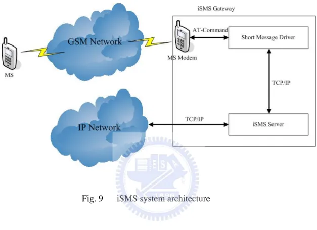
Fig.9 iSMS system architecture. . . .21
Fig.10 System architecture. . . 23
Fig.11 The SIP registration procedure in the SIP-based mobile
network. . . 30
Fig.12 The message flow to setup a session. . . 31
Fig.13 The message flow of the wireless interface network handoff. . 34
Fig.14 Sleep procedure. . . 39
Fig.15 Wake-up process. . . 41
Fig.16 Session transfer process. . . .43
Fig.17 The implementation of our system architecture. . . .46
Fig.18 The software architecture of SIP-MNG. . . .50
Fig.19 The processing flow chart of the packets coming from the inside
MANET. . . .51
Fig.20 The processing flow chart of the packets coming from the
outside internet. . . 52
Fig.21 The flow chart of the external link status change handling in
CAC. . . .54
Fig.22 The push server software architecture . . . .56
Fig.23 The two software module flow chart in push server. . . 57
Fig.24 A “wake-up” message sent from push server to SIP-MNG. . . .59
Fig.25 A testing environment of our SIP-based mobile network
system. . . 61
Fig.26 Uplink traffic load against the number of concurrent calls using
one PHS/WCDMA/802.11b interface. . . .62
Fig.27 The SIP mobility procedure when an IEEE 802.11 network
handoff occurs. . . .64
List of Tables
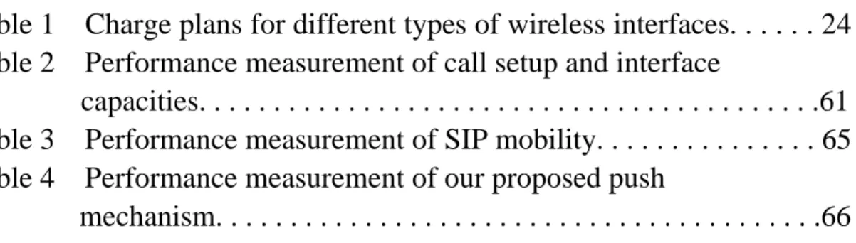
Table 1 Charge plans for different types of wireless interfaces. . . 24
Table 2 Performance measurement of call setup and interface
capacities. . . .61
Table 3 Performance measurement of SIP mobility. . . 65
Table 4 Performance measurement of our proposed push
Chapter 1
Introduction
As mobile devices are gaining more popularity, users expect to connect to the Internet at anytime and from anywhere. Extensive research has focused on how to maintain the global reachability of a device without interruption even when it is moving around [1, 2, 3]. In [3], it has proposed methods for mobile devices to continue their sessions when address changes. However, these host mobility management schemes manage mobility and connectivity of mobile devices in an individual manner. Group mobility is not addressed. For example, in a transportation carriage, there may exist tens/hundreds of users roaming together. If managing users in a one-by-one manner, not only the core network has to track each user individually, but also all users have to consume computation and radio transmission power to maintain their connectivity to the Internet. Clearly, supporting host mobility when users exhibit group mobility causes significant costs. Instead of tracking individual users' mobility, a concept called Network Mobility (NEMO) [4, 5] is proposed recently. NEMO packs all users in a vehicle as a network unit and conducts mobility
management through a gateway/router in the mobile network. Supporting vehicular networking services by NEMO provides following advantages: 1) there is less power consumption for a mobile device to connect to the local gateway/router than to a base
station (BS) outside the vehicle; 2) the complexity of mobility management is lower or even transparent for a mobile when connecting to a local gateway/router; and 3) there are fewer handoffs since the MAC layer handoff only occurs on the central gateway/router rather than on all mobile devices and the mobility management of a single gateway/router can ensure the reachability of the whole group of users inside the gateway/router[6].
To support NEMO, the Internet Engineering Task Force (IETF) has created a working group, where a Mobile IPv6-based NEMO (MIPv6-NEMO) protocol is proposed [7, 8, 9]. In a mobile network, there is a central node called Mobile Router
(MR), which can connect to the Internet and provide networking services for the
attached mobile devices. The MR has a home network and is assigned with one or more address blocks belonging to the home network, called mobile network prefixes, which can be assigned to the attached devices. Whenever the mobile network changes location, the MR will update with its Home Agent (HA), so packets addressed to the mobile network prefixes will still be routed to the mobile network from the home network. In addition to the MIPv6-NEMO, the Session Initiation Protocol-based
NEMO (SIP-NEMO) is proposed in [10]. In SIP-NEMO, central to the mobile
network is a SIP Network Mobility Server (SIP-NMS), which is responsible for the mobility management of the mobile network. Each SIP-NMS has a SIP Home Server
(SIP-HS), which records the current location of the SIP-NMS and forwards requests to
the SIP-NMS. SIP clients can communicate with each other directly without tunneling. So, SIP-NEMO also provides an additional way to achieve route optimization and tunnel header reduction for network mobility. However, both MIPv6-NEMO and SIP-NEMO schemes have following shortcomings: 1) Wireless resource is limited and valuable, but both architectures do not consider how to manage wireless resources to guarantee QoS of sessions and how to dynamically adjust its bandwidth to the Internet. 2) Both methods use an always-on approach, which means that the central gateway/router has to continuously collect network advertisements and deal with handoffs even when the network has no sessions for a long period of time. This will incur unnecessary charges and energy consumption for the external wireless interfaces. 3) For SIP-NEMO, in addition to existing SIP servers, extra servers, such as SIP-HS and SIP-FS (SIP Foreign Server), are required. This will increase the implementation cost for public transportation operators. 4) Wide spread of SIP-FS deployment is needed in all foreign network domains that users may roam into. This causes significant barrier for such services to be widely accepted.
Also based on the NEMO concept, this paper proposes to combine the innate mobility and scalability of MANET with a SIP-based mobile network architecture to support vehicular networking services for users on the roads. Our system is designed
over IPv4. Compared to SIP-NEMO [10], our system only needs an additional
SIP-based Mobile Network Gateway (SIP-MNG), which follows the SIP standard and
is compatible with the existing SIP framework, in each mobile network. No extra servers are needed in foreign networks. In our implementation, the SIP-MNG connects to the intra MANET by some IEEE 802.11 interfaces configured at the ad hoc mode and attaches to the Internet through one or more external wireless interfaces (such as GSM, GPRS, PHS, 3G, WiMAX, and IEEE 802.11 interfaces). These
external interfaces allow the SIP-MNG to provide dynamic bandwidths to the Internet according to users' demand and roaming characteristics. For example, by exploiting the session parameters carried by SIP signaling (such as session type, codec,
bandwidth requirement, ...), our SIP-MNG can support resource management (RM) and call admission control (CAC) to guarantee the QoS of sessions. Therefore, wireless resources are utilized efficiently.
Although the aforementioned system is quite attractive, dialing to the Internet (via wireless interfaces) incurs charges, power consumption, and maintenance overheads. When there is no Internet activity, it is desirable to disconnect the SIP-MNG's wireless interfaces to save energy and cost. However, this will result in users inside our system unreachable by other users. To solve this problem, we exploit the SIP session control feature and propose to establish a push server in the Internet as
a representative of our system when being disconnected. When a SIP request arrives, we develop a push mechanism by dropping a short message to the SIP-MNG to “wake up” the connection by redialing to the Internet. Once the SIP-MNG resumes its
connection, it informs the push server its contact address of the destined MH. Via the contact, the push server can transfer the suspended session to the MH by the SIP session transfer. Therefore, the proposed push mechanism can guarantee reachability of users in the mobile network, while saving energy, cost, and wireless resources.
The push mechanism has also been used in other applications. In GPRS networks, a MH must activate a PDP context before the corresponding service can be used. However, maintaining a PDP context without actually using it will consume network resources. So, short messages are used in [11] to activate a PDP context on-the-fly. For a dual-mode handset (with a cellular and a WLAN interfaces, for instance), to reduce energy consumption, it is desirable to disable the handset's WLAN module when it is not used. However, this will prevent the handset from receiving incoming VoIP calls from the WLAN interface. To solve this problem, reference [12] uses a paging mechanism via the cellular interface to inform the handset to activate its WLAN module. Then the VoIP call can be connected via the relatively inexpensive WLAN. However, both [11, 12] involve some modifications on SIP components and end devices to support such functions, which is undesirable. In addition, because of
the overhead to go through the push procedure, both approaches may suffer from the timeout problem if the callee's response time exceeds a predefined threshold. In our architecture, the standard protocols in SIP servers and SIP clients are unchanged. Also, with an external server and SIP call control feature, our approach can effectively relieve the timeout problem.
This paper is organized as follows. Chapter 2 presents some related work of this thesis. Chapter 3 introduces our system architecture to support vehicular networking services and the design motivation. Detailed system operations are presented in Chapter 4. The push mechanism is discussed in Chapter 5. Chapter 6 describes the prototyping results. Chapter 7 presents our performance measurement results. Conclusions are drawn in Chapter 8.
Chapter 2
Related Work
2.1 VoIP
Voice Over IP(VoIP) is regarded as one of the killer services among the mobile internet services. Our study uses the Session Initiation Protocol(SIP)[3] as the call initiation protocol for VoIP services. It’s standardized by the Internet Engineering Task Force(IETF) and has been adopted by many venders for internet telephony. SIP also has been extended to provide presence, event notification and instant message services[13].
SIP is a text based client-server protocol. It works like Hyper-Text Transfer Protocol(HTTP) to control call behavior. It often cooperates with other protocols, such as Session Description Protocol(SDP)[14] to describe session characteristics and Real-Time Transport Protocol[15] to send traffic after call setup. SIP endpoints are addressed by SIP URLs(Uniform Resource Locators), which have the form of email address, for example, [email protected]. SIP defines logical entities, namely user agents, redirect servers, proxy servers and registrars. User agents(UA) originate and terminate requests. Redirect servers receive requests and respond the requesters where their messages should be sent to. A proxy server is responsible to route SIP messages. A Registrar is a database server which records the location(s) of a user.
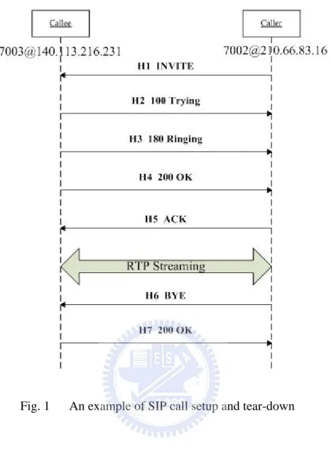
Fig. 1 An example of SIP call setup and tear-down
Typically, a proxy or redirect server is implemented with a built-in registrar. Figure 1 shows an example of call establishment where a caller with SIP
URL([email protected]) wants to set up a call with a callee with SIP
URL([email protected]). The caller invites the callee to set up a call by sending an INVITE request, which includes session information in the SDP such as supported codecs, the received ip address and port number of the caller(H1). If the callee accepts the INVITE request, it replies a 180 Ringing(H3) and a 200 OK(H4) responses to the
callee. On receiving the 200 OK message, the caller will response an ACK message to the callee(H5). Then, the call is established.
2.2 NAT Traversal for VoIP
Network Address Translation(NAT) is defined by RFC 1631[16]. It is being used by many service providers and private individuals as a way to solve the problem of lacking public IP addresses. NAT solves this problem by mapping internal addresses to limited external or public addresses. There are three mapping technologies, static NAT, dynamic NAT, and Network Address Port Translation (NAPT). Both of static NAT and dynamic NAT use the one-to-one address mapping. For static NAT, a private IP(ai) always maps to a fixed public IP(bi). In contrast with the static NAT, the
dynamic NAT only generates the mapping when necessary. In this scheme, a dynamic NAT router will maintain a free external IP pool. A free external IP is mapped to an inside private IP only when the latter wants to communicate to an external mode. So, the dynamic NAT is a suitable scheme when the number of inside PC is greater than the number of public IPs. In NAPT, many private hosts share a single public address. Figure 2 illustrates the NAPT scheme. For the NAT router, it identifies each session using different port number. One port is used for a translation between a private IP address and port number. It’s very useful when an individual may have a DSL
Fig. 2 The NAPT scheme
connection with one IP address, but want to have multiple computers hooked up to the Internet. In our mobile gateway, the NAPT scheme is used.
However, SIP has some inherent problems with NAT traversal. The first problem is, if a session is initiated by an external host, since there is not yet an address
translation mapping entry existed for the destined internal host behind the NAT router in the NAT router, so the internal host can not be reached from the external host. The second problem is, the private media IP address and port number of an internal host in SDP will not be translated by the NAT router, so the incoming media packets can not be routed to the internal host. The third problem is, the SIP contact header of an internal host is its private IP address, so it can not be routed. To solve these problems, an Application Layer Gateway(ALG)[17], which perform address and port translation in the application layer, for SIP is required. For outgoing packets, ALG searches the
internal host address in the application layer and replaces them by the translated address. On the contrary, for incoming packets, ALG will translate the public address back to the destined private address and forward these packets to the destined internal host. To solve the SIP signaling NAT traversal problem, a SIP ALG is implemented in our proposed mobile gateway.
2.3 Mobility Management
The Internet Engineering Task Force(IETF) has in recent years, developed protocols such as Mobile IPv4(MIP)[1] and Mobile IPv6(MIPv6)[2] to support continuous connectivity for mobile hosts(MHs). This scheme is known as the host
mobility. To be transparent to the network handoff in MIP, a MH keeps its address
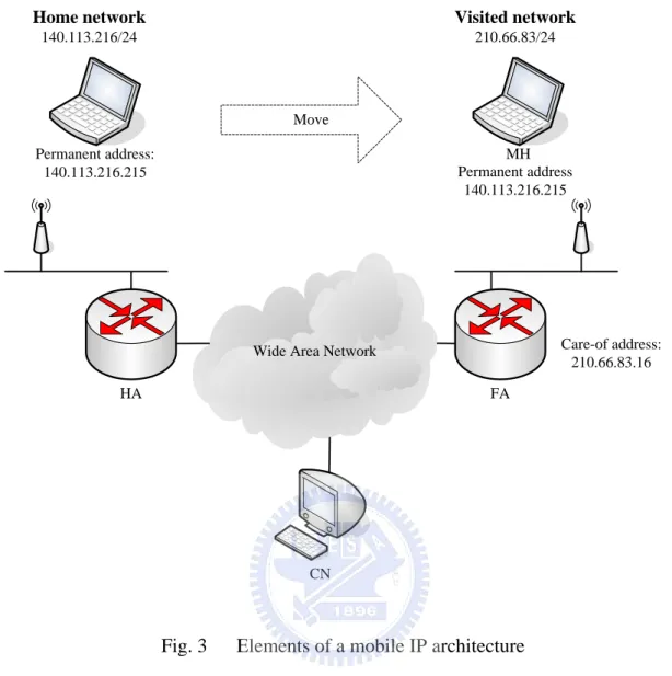
when it moves from one network to another. To maintain the reachability of the MH, a node called Home Agent(HA), which is located in the MH’s home network, will track the foreign network, where the MH visits. In each foreign network, there is a node called Foreign Agent(FA), which periodically broadcasts advertisement message in its network. Each FA has a unique address called care-of address(COA), which can identify a foreign network, so when a roaming MH receives an advertisement message with new COA, it detects the network change and updates to its HA with the new COA. Consequently, the HA tunnels the packets destined for the MH to the new
Wide Area Network FA MH HA CN Permanent address: 140.113.216.215 Care-of address: 210.66.83.16 Home network 140.113.216/24 Visited network 210.66.83/24 Permanent address 140.113.216.215 Move
Fig. 3 Elements of a mobile IP architecture
FA. Then, the FA can forward them to the inside MH. Figure 3 shows the MIP system architecture proposed by IETF. The MH is initially in its home network and connects to a corresponding node(CN). Then, it moves to the visited network, which is
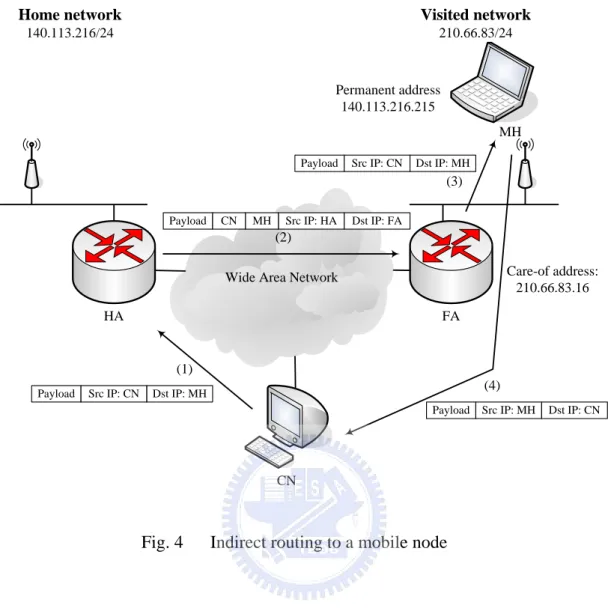
managed by the FA with COA as 210.66.83.16. Next let’s see how the datagrams are addressed and forwarded to the mobile node after the MH moves into the visited network. As shown in Figure 4, the HA looks out for arriving datagrams which
Wide Area Network FA MH HA CN Care-of address: 210.66.83.16 Home network 140.113.216/24 Visited network 210.66.83/24 Permanent address 140.113.216.215 (1) (2) (3) (4)
Payload Src IP: CN Dst IP: MH
Payload CN MH Src IP: HA Dst IP: FA
Payload Src IP: CN Dst IP: MH
Payload Src IP: MH Dst IP: CN
Fig. 4 Indirect routing to a mobile node
source address as HA’s address and destination address as the COA(2). On receiving these datagrams, the FA decapsulates them and forwards the original datagrams to the MH(3). Following this method, MIP manages hosts’ mobility and maintains their continuous connectivity.
However, the host mobility scheme is insufficient due to two reasons. Firstly, not all devices in a mobile network, such as sensors on an aircraft, are sophisticated enough to run these complex protocols. Secondly, once a device has attached to a MR(Mobile Router) on a mobile network, it may not see any link-level handoff even
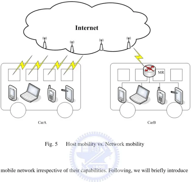
as the network moves. Therefore, the mobility management protocols need to be extended from host mobility to network mobility. Network mobility is namely a set of hosts that move collectively as a unit. This scenario can usually be seen on buses, ships, and aircrafts. There are tens/hundreds of passengers in a transportation carriage and move together. Figure 5 illustrates the difference between host mobility and network mobility. In CarA, even though the inside devices move together, each
handles its mobility itself. In CarB, inside devices connect to the Internet through MR. Since the MR and the inside devices move together, the latter does not have to pay cost for mobility management. All handoffs are handled by the MR. This also largely reduces the handoff signaling.
The IETF has created a working group called Network Mobility(NEMO)[7, 8, 9] that proposed a MIPv6-based NEMO(MIPv6-NEMO) protocol. MIPv6-NEMO allows session continuity for every node in the mobile network as the network moves. It also maintains the reachability of every node on the mobile network while moving around. A mobile network is a network segment or subnet that can move and
attach to arbitrary points in the network infrastructure. It can only be accessed via specific gateways called Mobile Routers (MRs) which manage mobile network’s mobility. MR and its HA run the MIPv6-NEMO protocol, which is a similar
Fig. 5 Host mobility vs. Network mobility
mobile network irrespective of their capabilities. Following, we will briefly introduce the MIPv6-NEMO protocol.
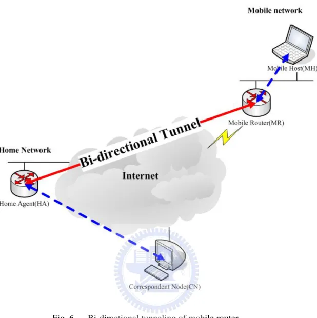
Firstly, the MR is assigned to one or more mobile network prefixes by its HA. The MR has to update its latest location to its HA. Once the HA intercepts packets addressed to the mobile network prefixes, since the latest location information of the MR is maintained, it will tunnel them to the MR (by its care-of address). On the receipt of these packets, the MR decapsulates and forwards them to the inside MHs. Packets in the reverse direction are also tunneled via the HA in order to overcome Ingress filtering restrictions[18]. In this case, the HA decapsulates the packets and
forwards them to the CNs. Figure 6 shows the bi-directional tunnel between MR and HA. This tunneling of packets is very similar to MIP and MIPv6. However, NEMO differs from them in that the MR updates the HA with the location of the entire mobile network, not just itself.
2.4 Push Mechanism
Because the power consumed by a wireless LAN interface occupies a great ratio on battery-operated devices, a lot of research has tried to reduce the energy
consumption by these devices. To conserve the energy used by a WLAN device, the power saving mode (PSM) defined in the IEEE 802.11 is widely employed[19], which switches a wireless interface into sleep mode when it is idle. However, instead of simply leaving the WLAN interface in the sleep mode, turning it off completely will reduce more power consumption. To do this, [20][21][22] propose the idea of using a secondary out-of-band low power interface to wake up the closed WLAN device only when needed, called push mechanism. In [21], a low power radio access interface is designed and added into the WLAN device. When there is no traffic, MHs can turn off the WLAN interface and listen to the messages from the low power radio. Once there are packets destined for disconnected MH, WLAN access points (APs) can inform the MH to activate its WLAN interface and receive these packets by sending
Fig. 6 Bi-directional tunneling of mobile router
messages to the low power radio. In [22], Feng et al. propose a push mechanism to activate the WLAN interface by sending a short message via cellular networks. In this approach, a cellular interface is equipped with a MH, which consumes much less power than the WLAN module, and is always on. When a SIP call request for the MH is received by the SIP server, a SPC(SIP-based push center) module in the SIP server will check if the MH is connected to wireless networks. If yes, the request is directly forwarded to the MH. Otherwise, the call is suspended, and the SPC will send a short
message to the MH to activate its WLAN interface. After the wireless connection is activated, the MH sends a message to inform the SPC. On receiving the message from the MH, the SIP server then delivers the suspend call request to the MH, and the standard SIP call setup procedure will be continued.
2.5 GSM Short Message Service(SMS) with IP Network
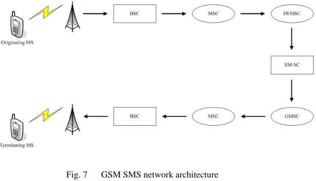
Global System for Mobile Communications (GSM) provides Short Message Service (SMS) which is a connectionless transfer of messages with low-capacity. Figure 7 shows the GSM SMS network architecture. In this architecture, when a Mobile Station (MS) sends a short message, this message is delivered to the GSM radio system. The radio system then forwards the message to the Mobile Switching Center (MSC) called SMS Inter-Working MSC (IWMSC). It passes this message to a Short Message Service Center (SM-SC). The SM-SC then forwards the message to the destination GSM network through a specific GSM MSC called the SMS Gateway MSC (SMS GMSC). Then the SMS GMSC locates the serving MSC of the message receiver and forwards the message to that MSC. This MSC will broadcast the message to the BTSs. On receiving the message, the BTSs will page the destination
MS(receiver), and send the message to it. So far, the short message transmission completes.
Fig. 7 GSM SMS network architecture
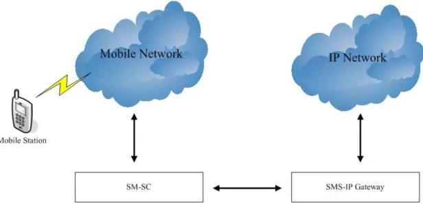
GSM SMS and IP networks can be integrated through Short Message Service Center (SM-SC). Figure 8 shows the architecture of SMS-IP integration with SM-SC. In this architecture, a special gateway must exist to associate the SM-SC to the IP network, where a specific protocol is essential for the communication between the SM-SC and the gateway.
Since both SM-SC and SMS-IP gateway are controlled by GSM operators, it is difficult for a third party to deploy new services via SMS. To address this issue, in [23], an endpoint SMS-IP integration solution, called iSMS, is proposed to provide an environment for quickly prototyping and hosting wireless data services. The iSMS system architecture is illustrated in figure 9. As shown in the figure, the iSMS gateway connects to an MS modem instead of SM-SC and consists of two parts. One is iSMS servers, which is responsible to provide services, the other is short message
Fig. 8 SMS-IP integration with SM-SC
driver, which interconnects the GSM network and the iSMS servers in the IP network. The short message driver and the iSMS servers can be implemented in a single host or separated. In the later case, the short message driver and the iSMS servers
communicate with each other through TCP/IP protocol. When the short message driver receives an incoming short message from the MS modem, it will pass them to the specific iSMS server according to the service type requesting by the received short message. On receiving the outgoing message from an iSMS server, the driver will transform it into the short message format and then send it out to the GSM network via the MS modem. By using the above model, a user can make a request from the GSM network by sending a short message to the MS modem which is connected to the iSMS gateway. Upon the receipt of the short message, the iSMS gateway executes
model is transparent to telecommunication operators, in this thesis, we adopt it in our proposed push mechanism.
Chapter 3
System Architecture and Motivation
Fig. 10 shows our SIP-based mobile network architecture, which contains a
mobile network subsystem and a SIP subsystem. The former is a SIP-based mobile
network connecting to the Internet. The latter includes some servers to support SIP-based networking services.
Central to the mobile network subsystem is a SIP-based mobile network gateway (SIP-MNG). It is equipped with one or multiple wireless interfaces (such as GSM, GPRS, PHS, 3G, WLAN, and WiMAX interfaces) that can dial up to the Internet and some IEEE 802.11 interfaces to connect to the internal MANET. In real applications, cellular interfaces may be applied in freeways, country areas, and trains, while WLAN and WiMAX interfaces may be applied in hot-spot and metropolitan areas. The
MANET consists of a set of mobile hosts (MHs), each equipped with an 802.11 interface configured at the ad hoc mode. Because real-time services are stringent in responsiveness, routing in the MANET is supported by a proactive protocol, such as DSDV [24] and CGSR [25], which will attempt to maintain consistent, up-to-date routing information at each host.
Fig. 10 System architecture
database containing users' subscription and status information. Users need to send their SIP registrar SIP REGISTER request messages to update their current locations periodically or when IP changes. The SIP proxy is responsible for routing SIP messages. The SIP registrar and SIP proxy are logical entities and are commonly implemented in a single host, called a SIP server. The PSTN gateway interconnects the Internet and the PSTN. So, with the PSTN gateway, SIP servers can set up/receive calls to/from the PSTN, respectively. The push server is to support our push
disconnected from the Internet. This can prevent incoming requests to the mobile network subsystem from loss.
Before presenting the detail system operations of our system, we first introduce our design motivations.
z Saving charges of Internet access: Table 1 shows the charge plans for different types of wireless interfaces. The charge plans can be divided into three types: 1). Charge by time; 2). Flat rate; and 3). Charge by packet. Clearly, for charge plans 1) and 2), accessing the Internet for a group of users in a vehicle through a few wireless interfaces can save a great deal of charges for individuals. For plan 3), operators can save wireless resources.
Charge Plans Type of Interfaces
By time Flat rate By packet
GPRS √
3G √ √
PHS √ √
IEEE 802.11 √ √
WiMAX √ √
Table 1 Charge plans for different types of wireless interfaces
designed with CAC and RM mechanisms to guarantee the QoS of a real time or multimedia applications.
z Push mechanism to save charges, power consumption, and wireless
resources: Considering that the current battery technology for cell phones can
operate 2~5 hours when in active mode, but 5~14 days when in standby mode, it is desirable to disconnect the cellular interfaces of SIP-MNG to save power consumption when no Internet activity exists. Also, this can save charges for plans 1) and 3), too. Moreover, SIP-MNG does not need to collect network advertisements to maintain global reachability. Via SIP session control and SMS, we design a push mechanism to allow the wireless interfaces to stay off-line when there is no Internet connection and to be “woken up” when necessary. z An added service for public transportation operators: The public
transportation operators can use our system as an added service to attract customers. In addition, adding management functions (such as accounting) becomes easy via SIP-MNG.
z Backward compatibility: Our goal is to serve the existing SIP clients without modification. So, we design our system by adding some new servers that can work transparent to existing SIP clients.
handle a large number of handoff events if host mobility is used. With our architecture, BSs only have to handle the mobility of the SIP-MNG, thus significantly reducing BSs’ load.
z Saving the power consumption of MHs: Since a MH connects to the Internet via the central SIP-MNG, it’s power consumption is significantly reduced. z Decreasing the complexity of MHs: Since handoff events are handled by the
SIP-MNG, MHs do not have to do movement detection and location update. The design of MHs is simplified. This is also known as movement transparency.
Chapter 4
Basic Operations of the SIP-Based Mobile
Network
In this section, we discuss the basic network operations in our system. Since the MANET is considered a private network, to provide Internet access, the SIP-MNG serves as a NAT (Network Address Translation) server for MHs and is responsible for the translation of SIP messages. To achieve the NAT traversal for SIP, techniques such as ALG (Application Layer Gateway) [26], STUN (Simple Traversal of UDP Through NATs) [27], and ICE (Interactive Connectivity Establishment) [28] have been proposed. Here we adopt the ALG scheme in our SIP-MNG. Below, we will discuss the entrance and session establishment procedures and CAC, RM, and handoff mechanisms.
4.1 MH Joining the Mobile Network
When a mobile device moves into a vehicle with the proposed SIP-based mobile networking services, its IEEE 802.11 interface will detect the existence of the network. After attaching to the mobile network, the MH will get a new IP address from the SIP-MNG. With this address, the MH can actively send a SIP REGISTER message to its SIP server to update its contact information. The REGISTER message will trigger
the SIP-MNG to serve as a representative of the MH. Fig. 11 shows the detail procedure of the SIP registration. In this scenario, we assume the MH UA-A gets an IP address 192.168.0.1 from the SIP-MNG, and its SIP URL is
sip:[email protected]. Addresses of the SIP-MNG and UA-A's SIP server are SIP-MNG.NEMO.com and SIPsvr-A.mobile.com, respectively. In the registration procedure, UA-A first sends a SIP REGISTER message to its SIP server with Via and Contact fields equal to 192.168.0.1 and sip:[email protected], respectively. Since the SIP-MNG monitors and translates all SIP messages to/from the Internet, it will capture the REGISTER message. On intercepting the message, the SIP-MNG will record UA-A's affiliation by adding UA-A's information into a SIP client table and relay the message by translating the Via and Contact fields into
SIP-MNG.NEMO.com and sip:[email protected], respectively. On receiving the SIP REGISTER message, the UA-A's SIP server will update UA-A's information and then reply a SIP 200 OK message. Since the Via field in the REGISTER request is translated into the SIP-MNG's address, the 200 OK message will be forwarded to the SIP-MNG. Also, with the SIP-MNG's address as the contact address, UA-A's SIP server can later forward SIP request messages destined for UA-A to the SIP-MNG, which will then relay them to UA-A. Upon the receipt of the 200 OK message from UA-A's SIP server, the SIP-MNG will translate the Via and
Contact fields back to UA-A's address and relay the SIP response to UA-A. Then, the SIP registration procedure is completed.
4.2 Session Setup Procedure and CAC and RM Mechanisms
In this subsection, we present how a session is established between a MH in the MANET and an external CN (Corresponding Node). We also discuss how our SIP-MNG supports CAC and RM. Recall that a SIP-MNG has one or more external interfaces. An interface is active if it has been dialed up to the Internet; otherwise, it is
idle. RM is responsible for evaluating the required bandwidth of a requested session
and assigning a serving external interface for the session. The required bandwidth can be estimated by the SDP (Session Description Protocol) [14] provided in the SIP signal. If any active wireless interface has sufficient spare resource, RM will assign it to the session. Otherwise, RM will activate a new wireless interface to serve the session. If all wireless interfaces are full, CAC will drop the SIP signal and reject the request.
Here we use a voice call request as an example to describe the detail message flow of session setup, CAC, and RM. Fig. 12 depicts the message flow, with some SIP headers omitted for simplicity. We assume that UA-A's IP address and SIP URL are 192.168.0.1 and sip:[email protected], respectively. CN's IP address and
Fig. 11 The SIP registration procedure in the SIP-based mobile network
SIP URL are 140.113.216.112 and sip:[email protected], respectively. For simplicity, UA-A and CN use the same SIP server, whose address is
SIPsvr.mobile.com. The SIP-MNG's address is SIP-MNG.NEMO.com. The corresponding call setup steps when UA-A calls CN are as follows.
1. UA-A sends a SIP INVITE message to the SIP server to invite the CN. c
(Connection Information) and m (Media description) fields in the sdp include the connection address and port information, respectively(by which UA-A can receive
Fig. 12 The message flow to set up a session
session; so RM can tell that this is an realtime/multimedia session.
2. When intercepting the SIP INVITE message, the SIP-MNG will initiate the CAC and RM procedures. CAC will accept the requested session if RM returns ok, and reject the session otherwise. RM includes three steps: 1) evaluate the required bandwidth; 2) allocate a wireless interface for the session if there is enough
bandwidth; and 3) return the status ok/failure to CAC. Since the codec information can be derived from the m field (18 = G.729, 3 = GSM, and 0 = G.711 mu-law) and the default packetization interval (PI) is 20 ms, the required bandwidth can be predicted. If there is no resource, the SIP-MNG will drop the SIP INVITE message and respond a SIP 480 “Temporarily not available” message to UA-A. Otherwise, the session will be recorded into a session table and relay this message to the SIP server after translation. Since the sdp provides multiple candidate codecs for the session, RM will preserve the maximum required bandwidth for the session. For non audio/video sessions (which will be described in field m), the SIP-MNG will reserve one or few wireless interfaces dedicated to these types of sessions. For such best-effort sessions, RM will skip the resource evaluation step and directly allocate an interface for it.
3. Then fields Via, Contact, c, and m fields of the SIP INVITE message are translated. In this example, the (connection address):(port) is translated from 192.168.0.1:9000 to 140.113.24.210:45678.
4. On receiving the SIP INVITE message, the SIP server forwards it to the CN, which will register the caller’s address as 140.113.216.112.
5. The CN then replies with a SIP 200 OK message, where it chooses G.729 as the final codec to communicate with UA-A. According to the Via header in the
received SIP INVITE message, this 200 OK message will be sent back to the SIP server at SIPsvr.mobile.com.
6. Upon the receipt of the 200 OK message, the SIP server forward it to address SIP-MNG.NEMO.com.
7. When the SIP-MNG receives the 200 OK message, RM will update the session table according to the final media information. Then, the SIP-MNG translates the 200 OK message and relays it to UA-A.
8. UA-A feedbacks SIP ACK message to the CN directly according to the Contact information in the received 200 OK message.
9. The SIP-MNG relays the SIP ACK message to the CN after translating the Via header. Then the call is established.
4.3 Handoff Procedure
As the vehicle moves, an external interface may change its network domain and the SIP-MNG may change its active interface. In both cases, a handoff happens. The SIP-MNG must recover sessions on these handoff interfaces by sending re-INVITE messages and maintain the global reachability of all MHs in the MANET by sending
Fig. 13 The message flow of the wireless interface network handoff
re-REGISTER messages. Since recovering on-going sessions is more urgent, it will be done first. Below, we outline the detail steps (refer to Fig. 13).
1. According to the SIP_client_table and the session table, the SIP-MNG retrieves the endpoint MHs and CNs of the on-going sessions on each handoff interface. 2. The SIP-MNG then sends each CN a SIP INVITE message to re-invite it. 3. A CN, on receiving the SIP INVITE message, will register the new contact
4. On receiving the 200 OK messages, the SIP-MNG will update the session table and reply the corresponding CN a SIP ACK message. Then, the session between the CN and the MH can be continued.
5. After recovering all handoff sessions, the SIP-MNG will send a SIP REGISTER message for each MH that has changed to a new external interface to update its contact address.
6. When a SIP server receives the above SIP REGISTER message, it will update the corresponding MH's data and reply a SIP 200 OK message. After this, all MHs are guaranteed to be reachable from outside.
4.4 MH Leaving the Mobile Network
When a MH leaves the mobile network, it may detect other network and update its contact information by sending a SIP REGISTER message. If there is an on-going session, it can be resumed by SIP re-INVITE. However, since the MH does not deregister with the SIP-MNG, the SIP-MNG will keep its information in the SIP client table. If the MH has an on-going session before it leaves, the SIP-MNG will still reserve resource for the session. Fortunately, if a SIP request arrives, because the MH does not exist in the network, a new session will not be set up. However, the allocated resource will never be released. To solve this problem, we suggest to set a
timer for each session and integrate the SIP-MNG with the underlying routing protocol in the MANET. If the SIP-MNG finds that the MH does not exist after the timer times out, the corresponding resource will be recycled. Noted that the SIP-MNG can determine whether a specific MH exists or not by searching the corresponding entry in the routing table. Alternatively, the SIP OPTIONS message can be used to query the capability of a SIP client or server. The message should be responded with a SIP 200 OK response with the supported capabilities. This can be used to determine a MH's existence.
Chapter 5
The Proposed Push Mechanism
Our system allows the external interfaces of SIP-MNGs to be disconnected when there is no Internet connection. When any interface is connected, the mobile network becomes a part of the Internet, so all sessions can be handled as usual. When all interfaces are disconnected, if an outgoing SIP request is sent by a user in the mobile network, the SIP-MNG can buffer the invitation, dial up to the Internet, register this user with the SIP registrar, and then send the invitation to the callee. However, when the mobile network is out of reach from the Internet, an incoming SIP request can not be completed. To solve this problem, we propose a push mechanism.
In our push mechanism, the SIP-MNG will carry out a sleep procedure when it decides to disconnect from the Internet. Recall that there is a push server in the SIP subsystem (refer to Fig. 10). The SIP-MNG will solicit the push server as its agent during the disconnection period. When an incoming SIP request arrives, the push server will be notified first and will trigger a wake-up procedure, which includes a
wake-up process and a session transfer process. In the wake-up process, the push
server will activate the SIP-MNG via SMS (Short Message Service) and establish a connection with the caller to hold the session. After the SIP-MNG reconnects to the
Internet, the transfer process will help build the link between the caller and the
internal callee. In this way, the SIP-MNG can stay off-line but remain reachable from the Internet.
5.1 Sleep Procedure
To avoid modifying the existing SIP standard, the push server works as an agent for users inside the mobile network when the SIP-MNG is disconnected from the Internet. The sleep procedure is to inform the SIP server to redirect all SIP messages destined to mobile network users to the push server.
Fig. 14 shows the message flow of the sleep procedure. When there is no Internet connection, the SIP-MNG may initiate the sleep procedure by sending a sleep request to the push server (H1). The sleep request includes the SIP URIs of MHs inside the mobile network and the MSISDN (Mobile Station International ISDN Number) of one of the cellular interfaces of the SIP-MNG. The MSISDN will later be used by the push server to notify the SIP-MNG of new incoming SIP requests via short messages. The push server maintains a gateway table and a SIP client table. Each entry in the gateway table is to track the status of one SIP-MNG and includes four fields: gateway id, status, MSISDN, and IP address. Each entry in the SIP client table is to track one MH and includes three fields: SIP URI, SIP-MNG id, and registration
Fig. 14 Sleep procedure
expiration time. On receiving the sleep request from the SIP-MNG, the push server updates these two tables and marks the status of the SIP-MNG as off-line. The push server then replies an OK to the SIP-MNG (H2). Upon receipt of the OK message, the SIP-MNG will generate REGISTER messages for all internal SIP clients to their corresponding SIP servers (H3) with an EXPIRE value of 0 (which means unregister). In return, the SIP server will reply SIP 200 OK messages (H4). On the other hand, as soon as the push server replies an OK message to the SIP-MNG (H2), it also sends REGISTER messages for all MHs served by the sleeping SIP-MNG to their SIP servers with a non-zero EXPIRE value (H5). These REGISTER requests should contain the push server's IP address in the CONTACT field, so that all future SIP INVITE requests to these MHs will be forwarded to the push server. Upon receipt of a
REGISTER message, a SIP server will update its record and reply a SIP 200 OK message to the push server (H6). After step H4, the SIP-MNG can disconnect all its wireless interfaces, and after step H6 the push server will become the agent of the mobile network subsystem and send periodic REGISTER messages for it.
5.2 Wake-Up Procedure
Consider a SIP request from a SIP client UA1 in the Internet to a client UA2 in the mobile network. To complete this session, there are two parts in the wake-up procedure: wake-up process and session transfer process.
5.2.1 Wake-Up Process
Fig. 15 illustrates the message flow of the wake-up process. To set up a session to UA2, UA1 first sends a SIP INVITE message to UA2's SIP server containing the session information, connection address, and port number of UA1 in the SDP (F1). The SIP server will identify that the contact of UA2 is the push server and forward the INVITE to the push server (F2). The push server then checks its SIP client table and gateway table and retrieves UA2's SIP-MNG information. Because the status of the SIP-MNG is off-line, the push server will send a short message to the MSISDN registered by the SIP-MNG (F3). This short message carries the event type and IP
Fig. 15 Wake-Up process
address of the push server to inform the SIP-MNG to reconnect to the Internet. In the meantime, the push server will temporarily set up the session with UA1 to keep the session alive (F4-F7). This can prevent the SIP signaling from timeout. If this is a voice call request, to be more friendly, an option is to have the push server prepare a pre-recorded voice to tell UA1 to wait for the call to be transferred. On the other hand, when the SIP-MNG receives the short message, it will reconnect to the Internet and re-register for all MHs inside the mobile network (F8, F9) using the IP address of any active external interface of the SIP-MNG in the CONTACT field. Also, the SIP-MNG will reply an OK message to the push server via its Internet connection to update its status with the push server (F10).
5.2.2 Session Transfer Process
Next, the session needs to be transferred from the push server to UA2. Fig. 16 depicts the message flow. The process is based on the REFER method [29] proposed by IETF to support session mobility. We comment that IETF also proposes an alternative third-party call control (3pcc) [30]. Requiring no special servers, both REFER and 3pcc are standard SIP solutions to support session mobility and fit our needs well. We adopt the REFER method because it requires less efforts for the push server.
After accomplishing the wake-up process, the push server will send UA1 a
REFER request containing the contact information of UA2 in the Refer-To field (F11). This message triggers UA1 to invite UA2 using the contact in the Refer-To field. UA1 then replies a SIP 202 Accepted response to the push server to indicate its approval (F12). To inform the push server that it is establishing a session with UA2, UA1 will also send a SIP NOTIFY message to the push server with an indication of “SIP/2.0 100 Trying” in the message body (F13). On receiving the NOTIFY message, the push server will respond a SIP 200 OK response (F14). The push server then
Fig. 16 Session transfer process
sends a SIP BYE request to UA1 to terminate their session (F15). UA1 will reply a SIP 200 OK (F16). However, the dialog between the push server and UA1 will be maintained until the subscription created by the REFER is terminated.
To set up a session with UA2, UA1 sends a SIP INVITE request to UA2 containing the SDP that describes the session information of UA1. Then the rest of the SIP signalings follows the normal session setup flow (F17-F20). After the session between UA1 and UA2 is connected, UA1 will report to the push server the success of the session setup and terminate the Refer-To subscription by sending the push
server a SIP NOTIFY message (F21) containing a Subscription-State header field with content of “terminated; reason=noresource". Then, the push server will respond a SIP 200 OK message (F19). The dialog between the push server and UA1 will then be terminated. To stop acting as an agent of the mobile network subsystem, the push server may send REGISTER messages for all SIP clients inside the SIP-MNG to their SIP servers with an EXPIRE value of 0 (F23). In response, the SIP servers will sent 200 OKs (F24).
Note that a MH may simply leave the network without giving any notification. We have discussed some timeout mechanisms to determine a MH's existence. If the SIP-MNG knows that the callee has left the network, it will not activate any external interface. Otherwise, an interface will be activated, but no MH will accept the INVITE message. So our system still works correctly.
To summarize, in our push mechanism, no change is made on the behavior of the SIP registrar and SIP proxy. SIP clients still use the standard SIP signaling. A push server can serve multiple SIP-MNGs at the same time. The REFER method is also a standard. So the system is fully compatible with existing SIP standards. Short messages and new signaling are supported by our proprietary SIP-MNG and push server. Each SIP client inside the mobile network subsystem can still use its original SIP server, SIP URI, and configuration.
Chapter 6
Prototyping Results
This chapter describes our prototyping results. We will first present the overall prototype, development platforms and tools. Then, we will describe the
implementation details of the two core entities in our system: SIP-based mobile network gateway (SIP-MNG) and push server respectively.
6.1 Prototype, Development Platforms and Tools
Figure 17 shows our prototype of the proposed system, which contains a SIP
subsystem and a mobile network subsystem. The SIP subsystem includes three
components: SIP UA, SIP server, and push server. The SIP server is the combination of the two logical entities of SIP registrar and SIP proxy. In the prototype, we adopt the iptel SER[31] to be our SIP server. For the SIP UA, we select two SIP phone products to be our SIP client terminals. One is the D-Link wireline SIP phones; the other is the wireless SIP phones by BCM communication company. In addition to the basic features defined in rfc3261, the D-Link SIP phone supports the SIP REFER method. All SIP clients inside the MANET or in the Internet use the same SIP server as their home SIP server. The push server is implemented on an ASUS centrino notebook running the Windows XP. To carry out the push mechanism, the iSMS
Fig. 17 The implementation of our system architecture
software and the programming tool of Microsoft Visual C++ 6.0 are used. The push server is equipped with a Nokia card phone 2.0 to connect to the GSM cellular network.
The mobile network subsystem consists of a SIP-based mobile network gateway (SIP-MNG), short message service(SMS) relay, and a mobile ad-hoc network
(MANET). The SIP-MNG is implemented on an IBM T42 notebook running the Linux Fedora Core Release IV. The iptables, library libipq, GNU gcc, and g++ are
used as the programming tools to carry out it. The SIP-MNG is equipped with a cellular interface(PHS J88/Huawei E612 WCDMA PCMCIA), which connects to the Internet, and an ASUS WL-167G USB2.0 WLAN adaptor, which is configured at the ad hoc mode and connects to the inside MANET. When a PHS J88 cell phone is used as an external interface, the SIP-MNG drives it via a P-card MC-6550 PCMCIA card. The installation of PHS and PPP is illustrated in Appendix A. Since the iSMS
platform presently only supports Windows OS, to support SMS for SIP-MNG, an SMS relay is set up and connected to SIP-MNG directly via a RJ-45 cable. The SMS relay is equipped with a Nokia card phone 2.0 and installed with the iSMS platform. So, the SIP-MNG can send and receive short messages through it. In addition to the SIP-MNG, there is a BCM WiFi phone and a D-Link SIP phone inside the MANET. The BCM SIP WiFi phone is configured at the ad hoc mode. Because the D-Link SIP phone has no 802.11 interface, we connect it to an ASUS centrino notebook via its ethernet interface first, then connect the ASUS notebook to SIP-MNG via its 802.11 interface, and set the two interfaces in the bridge mode. As a result, the D-Link SIP phone can connect to the SIP-MNG through the ASUS notebook’s WLAN interface which is configured at the ad hoc mode.
As for the SIP-MNG and Push Server, we will describe their implementation details in the following.
6.2 SIP-Based Mobile Network Gateway(SIP-MNG)
The SIP-MNG is a gateway between the inside MANET and the outside internet. To implement the NAPT between the outside Internet and the inside MANET, the netfilter software and command iptables are used. Netfilter [32] is a set of hooks inside the linux kernel that enables packet filtering, network address(and port)
translation and other packet mangling. Iptables is a userspace command line program which is used to define packet filtering rules for netfilter. We also use them to
implement our RM&CAC and SIP signaling NAT traversal, because it can help to extract the SIP packets from the kernel. Below, we will describe how it works.
The iptables provides a kernel module, called queue handler, to perform the mechanics of passing packets out of the network stack and queueing them for the userspace programs. This provides a way for the userspace programs to monitor and process network packets. So, a userspace program can further choose to modify these captured packets before reinjecting them back to the network stack or drop them. The standard queue handler for IPv4 is the ip_queue module, which is distributed with the linux kernel. Once ip_queue is loaded, IP packets can be filtered and queued for userspace in the QUEUE target. QUEUE is a special target, which queues IP packets for userspace. The following is how we define the ruleset by iptables to realize NAPT
and queue SIP signaling packets for our userspace to carry out SIP signaling NAT traversal and RM&CAC.
1. # modprobe iptable_nat
2. # modprobe ip_queue
3. # /sbin/iptables –t nat –A POSTROUTING –s $INNET –o $EXTIF –j
MASQUERADE
4. # /sbin/iptables -t mangle –A FORWARD –p udp –dport 5060 –j QUEUE
5. # /sbin/iptables -t mangle –A INPUT –p udp –dport 5060 –j QUEUE
Line1 and Line2 are used to load the related iptables modules. Line3 is used to translate the ip address and port number between the inside MANET and the outside Internet, which carries out the NAPT. Line4 and Line5 are used to pass the SIP packets(default port for SIP is 5060) to the ip_queue module, which will then be processed by our SIP ALG and RM&CAC modules. To write an application layer program to handle the extracted packets in ip_queue, the Libipq library is required. It is a development library which provides APIs for userspace program to get and process queued packets in ip_queue. We use the libipq APIs to carry out our SIP signaling NAT traversal, RM&CAC, and SIP mobility. The included libraries and the APIs we used in our program are introduced in Appendix B. Figure 18 illustrates the software architecture in our SIP-MNG. In this figure, there are four main components:
Fig. 18 The software architecture of SIP-MNG
1) SIP UA handles all SIP signaling and SIP signaling NAT traversal; 2) RM&CAC manages the SIP-MNG’s external bandwidth and decides whether a new call shall be admitted or not; 3) SIP mobility is responsible for the mobility management of SIP sessions; 4) external link monitor is used to monitor the external link status. Below, we will describe each of them.
The SIP UA module is responsible for all incoming SIP signaling. Our SIP-MNG has two interfaces: One is the inside WLAN interface; the other is the external PHS interface. So, the SIP UA module will handle all SIP messages coming from the two interfaces. Fig. 19 illustrates how the SIP UA module handles SIP messages coming from the inside MANET. On receiving a SIP message, it first
2. Packets come from the inside
MANET 1. Receive and Parse SIP packet
3. REQUEST packet
5. Add it into SIP client table 19. 200 OK 4. REGISTER 8. INVITE 13. BYE/CANCEL 14. sipCloseSession Idle 11. 404 Not found/ 480 Temporarily not available 1XX 6. Forward to SIP server 20. Establish RTP connection Call Proceeding 3XX or more 7. Check SIP client table 17. Check SIP client table 18. Find SIP session table
16. Drop it 12. Check SIP session table Yes No Yes Yes Drop it No Yes Yes No No Yes Yes No Yes No No Yes Yes No Yes No No
Packets come from the outside Internet
15. Other Request 10. sipOpenSession Calling
Yes 9. RM&CAC
No 404 Not found
Fig. 19 The processing flow chart of the packets coming from the inside MANET
checks whether it is a SIP request or not(3). If it is a SIP request, the SIP UA module further checks if it is a SIP REGISTER message(4). If it is a SIP REGISTER, the SIP UA module will add the from SIP client into its SIP client table and translate it(5). If it is not a SIP REGISTER message, the SIP UA module will then check its client table(7). If the from SIP client is not in the table, the SIP UA module will drop the SIP message and respond the SIP client a 404 Not Found/480 Temporarily Not
Fig. 20 The processing flow chart of the packets coming from the outside internet
Available SIP message(11). If the from-SIP client exists and the SIP message is a SIP INVITE request(8), the SIP UA module will run RM&CAC module(9). If pass, then RM&CAC will create a new SIP session(10), and replace some SIP headers for NAT traversal and forward the INVITE message to the outside SIP server. On the other hand, if the incoming packet is a SIP response, the SIP UA module will check its SIP client table first(17). If the to-SIP client is in the table, it will find out which session the message responses(18). Then, if it is a 200 OK response(18), the SIP UA module
will use the following iptables command to establish the RTP connection(20) for the session, translate some SIP headers, and forward the 200 OK response to the outside SIP server. The following iptables command means that the incoming packets
destined for port 48000 are translated to the inside IP address 192.168.3.2 port 65530 and vice versa.
# /sbin/iptables -t nat -A PREROUTING -p udp -i ppp0 -d 210.66.83.0/24 --dport 48000
-j DNAT --to 192.168.3.2:65530
As for the SIP messages coming from the outside Internet, Fig. 20 shows the processing flow chart. It is similar to the procedure in Fig. 19.
For RM&CAC module, it records the link status of external wireless interface(s) and its(their) bandwidth. When intercepting a SIP INVITE request, SIP UA interprets the requested bandwidth of the SIP call and passes it to RM&CAC to compare with the remaining bandwidth. If bandwidth is insufficient, RM&CAC will inform SIP UA to respond a “480 Temporarily not available” message to reject the call request. If the remaining bandwidth is enough, RM&CAC will reserve bandwidth for the call and SIP UA will continue the SIP signaling exchanges. For external link monitor module, it is responsible for monitoring the link status of external wireless interface(s). When the link status of any external wireless interface changes, it will trigger a Link Status Change event to CAC. Figure 21 shows the flow chart of the external link change
handler in CAC. If CAC is notified with the external link status, it will record the interface status(1). Then, if it is an interface down event, CAC checks if there is any active call over the interface(13). If yes, to prepare session handoff operation, CAC will records the active calls over the disconnected interfaces into a handoff table(14). If CAC is notified that the external link is up again, it will record its bandwidth(3) and check whether the ip address of the external interface is changed or not(4). If the IP address is changed, the handoff table will be checked to see if there is any call over the interface(5). If there is any call over the interface, CAC will initiate the SIP mobility procedure by sending a re-INVITE request with the new IP address of the interface to make the session continue(6-8). Then, it will also execute SIP
re-registrations to update their new location(10, 11).
6.3 Push Server
The push server is used to support our push mechanism and can “wake up” the SIP mobile network gateway (SIP-MNG) when its external interface is disconnected from the Internet. Our push server is implemented over an ASUS centrino notebook which is equipped with a Nokia card phone 2.0 to connect to the GSM cellular
network. We implement a push server software which supports SIP REFER method to transfer a SIP call and controls the Nokia card phone to send short messages to the
Fig. 22 The push server software architecture
SIP-MNG to wake up its external interface. Because the Nokia card phone 2.0 is installed on the Windows OS platform, we use VC++ 6.0 to develop our push server software.
Figure 22 illustrates the push server software architecture. The SIP UA module supports SIP protocol stack and is responsible to negotiate with SIP Servers. The wake-up module is used to handle all events sent from push clients via TCP/IP. Figure 23 shows the flow chart of the two major software modules to execute the wake-up
7. Do nothing 2. Authorize the Push client
Yes
8. Reject it
Yes
No
No 1. Receive and Parse
packets from Push client
start
6. End 3. Update records in
the client record table
5. Trigger SIP UA to start unattended
call transfer start
1. Receive and Parse packets from SIP
server
2. INVITE
3. Check Push Client table Yes 8. Reject the INVITE No 7. Other SIP handling No 5. Trigger iSMS system to send SM to Push clients Yes 6. End 4. Accept the INVITE and play the transfer music to
caller
4. REFER event
(a) SIP UA module (b) Wake-Up module Fig. 23 The flow chart of SIP UA and Wake-Up modules to execute
the Wake-Up procedure of our push mechanism.
procedure of our push mechanism. When SIP UA module receives an INVITE request from SIP Server((a)-1, (a)-2), it checks its push client table which records the SIP clients it represented((a)-3). If the callee is in the table, it accepts the INVITE,
establishes and holds the call, and then plays the transfer music to the caller((a)-4) At the same time, the SIP UA module will trigger iSMS system to send a short message