www.elsevier.nl/locate/ultras
On the measurement of anisotropic elastic constants of
fiber-reinforced composite plate using ultrasonic bulk wave
and laser generated Lamb wave
T.-T. Wu *, Y.-H. Liu
Institute of Applied Mechanics, National Taiwan University, Taipei, Taiwan, ROC
Received 10 March 1999
Abstract
In this paper, we developed a hybrid elastic wave method to determine the anisotropic constants of a thin fiber-reinforced composite plate. The method is based on the measurements of the pure mode bulk ultrasonic wave velocities as well as the Lamb wave velocities. The formulae of the pure mode plane wave propagation in an orthotropic medium are summarized, first. Then, the numerical results of Lamb wave dispersion in a thin fiber-reinforced plate are presented. In the experimental part, conventional ultrasonic velocity measurements were conducted to obtain the pure mode velocities of a unidirectional fiber-reinforced composite and therefore the three corresponding elastic constants. The remaining two elastic constants of the thin composite plate were then obtained by using the inverse analyses of the Lamb wave dispersion. We note that with this hybrid method, some of the anisotropic constants can be measured accurately with well-developed bulk wave ultrasonics, while the rest of the undetermined elastic constants can be obtained from the inversion of the Lamb wave dispersion. © 1999 Elsevier Science B.V. All rights reserved.
Keywords: CFRP; Lamb wave; Laser ultrasonics; Non-destructive evaluation
1. Introduction in the field of non-destructive evaluation of materials. Since fiber-reinforced composite materials are aniso-Fiber-reinforced composite materials have been uti- tropic in nature, the conventional ultrasonic technique lized extensively in industrial applications, such as ship for measuring material constants in isotropic materials and aircraft engineering. Recently, they have also been cannot be utilized to obtain all of the anisotropic elastic applied to the retrofit of concrete structures. The key constants. In the literature, there are extensive researches feature of fiber-reinforced composite material is its high related to the study of ultrasonic waves in composite strength to weight ratio. The anisotropy of the material laminates. Datta et al. [2] utilized the stiffness method allows the strength to be utilized in a given design to study dispersive wave propagation in a laminated direction without the addition of extra weight resulting anisotropic plate. Rose et al. [3] utilized Lamb waves from strength in unnecessary directions. However, the to evaluate the anisotropic properties of graphite–epoxy complex constitutive nature of composite materials leads composites. Dayal and Kinra [4] examined the disper-to difficulties in the determination of their mechanical sion relations of the leaky Lamb waves in an anisotropic properties [1]. By conventional mechanical testing tech- plate and developed an experimental technique for meas-niques, the Young’s moduli along different principal uring phase velocity and attenuation of ultrasonic waves axes of symmetry of fiber-reinforced composites must
in thin plates. The propagation of free waves in plates be measured through different uniaxial tests. In addition
of general anisotropic materials was studied by Nayfeh to the Young’s moduli, the measurements of the shear
and Chimenti [5]. The experimental study of the propa-moduli of fiber-reinforced composites are also not easy,
gation of horizontally polarized shear waves in a unidi-the rail shear or torsion tube test must be invoked.
rectional thin fiber-reinforced composite plate was made Ultrasonic techniques have been applied successfully
by Wu and Chiu [6 ]. Laser generated ultrasonic surface waves [7] have also been applied to measure the elastic
* Corresponding author. Tel.:+886-2-2363-0979;
constants of anisotropic half space. The anisotropic
fax:+886-2-2363-9290.
E-mail address: [email protected] ( T.-T. Wu) elastic constants were obtained using the inverse analyses
0041-624X/99/$ – see front matter © 1999 Elsevier Science B.V. All rights reserved. PII: S 0 0 4 1 -6 2 4 X ( 9 9 ) 0 0 02 5 - 6
of the measured group velocities of laser generated Consider an orthotropic medium where the planes of orthotropic symmetry are taken as the coordinate surface waves. Veidt and Sachse [8] measured the
stiff-ness tensor of thin fiber-reinforced laminates based on planes; it is easy to find that for plane waves propagating in the direction of the axis of orthotropic symmetry, the the point-source/point-receiver technique. A simple
plane wave, plane stress model was utilized to describe motion may be either a pure longitudinal or a pure transverse wave. Therefore, six independent pure mode the quasi-longitudinal and quasi-transverse waves. On
the other hand, there are researches on the measurements waves exist, three longitudinal and three shear. Let V ij denote a wave propagating along the x
i-axis with polar-of elastic properties polar-of thin plates using Lamb waves
[9–12], but most of the test specimens are isotropic. ization in the direction of the x
j-axis, then the six wave speeds can be expressed in matrix form as [13]: In this paper, we developed a hybrid elastic wave
method to determine the anisotropic constants of a thin fiber-reinforced composite plate. The method is based
on the measurements of the pure mode bulk ultrasonic [rV2 ij]=
C
C 11 C66 C55 C 66 C22 C44 C 55 C44 C33D
(5) wave velocities as well as the Lamb wave velocities. Inthe following, the formulae of the pure mode plane wave propagation in an orthotropic medium are
summa-where the elastic constants have been written in Voigt’s rized, first. Then, the numerical results of Lamb wave
contracted notation, in which 11 is replaced by 1, 22 by dispersion in a thin fiber-reinforced plate are presented.
2, 33 by 3, 23 by 4, 31 by 5, and 12 by 6. In the experimental part, the conventional ultrasonic
velocity measurements were conducted to obtain the
2.2. Pure mode waves in a unidirectional thin
fiber-pure mode velocities of a unidirectional fiber-reinforced
reinforced composite laminate
composite and then the corresponding elastic constants. Finally, laser ultrasonic experiments were conducted to
A unidirectional fiber-reinforced composite thin plate obtain the Lamb wave dispersion and an inverse
algo-can be assumed as in transversely isotropic symmetry, rithm was utilized to determine the remaining two elastic
and hence, the independent elastic constants are reduced constants of the thin unidirectional composite plate.
from nine (orthotropic) to five. Let the x
1-axis be pointed along the fiber direction, then the x2–x3 plane is the isotropic plane (Fig. 1). The non-vanishing elastic
2. Bulk ultrasonic wave measurement constants are:
2.1. Plane waves in orthotropic media
For an anisotropic linear elastic material with no body force, the equation of motion for the wave
displace-[C ij]=
C
C 11 C12 C12 0 0 0 C 12 C33 C23 0 0 0 C 12 C23 C33 0 0 0 0 0 0 C 44 0 0 0 0 0 0 C 55 0 0 0 0 0 0 C 55D
(6) ment uihas the form:
C ijkl ∂2ui ∂xj∂x l =r∂2ui ∂t2 (1) where C
ijkl are the elastic constants and r is the mass where C44=(C33−C23)/2.
density. A plane wave propagating in the medium can From Eq. (5), we understand that for wave propaga-be represented as: tion in such an anisotropic plate, pure wave mode
u
i=Uiexp[ik(njxj−Vt)] (2) where U
i is the amplitude, k the wave number, nj the wave normal, and V the phase velocity of the plane wave. On substituting Eq. (2) into Eq. (1), the phase velocity and wave amplitude must satisfy the following system of equations:
C
ijklnjnl−rV2dik)Uk=0 (3) where V is determined from the characteristic equation:
K
C( longitudinal or transverse) exists only when the propa-gation direction is along or perpendicular to the fiber direction. For all the other propagation directions, the wave modes are quasi-longitudinal or quasi-transverse. We note that for bulk ultrasonic wave measurement in such a thin plate, the only accessible plane is the x1–x2 plane (see Fig. 1), and therefore, it is not feasible to measure the phase velocity with propagation direction along x1- or x2-direction. For wave normal pointed along the x
3-direction, the relations between the phase velocities and the elastic constants can be obtained from Eq. (5) as: V 31=
S
C 55 r , V32=S
C 44 r , V33=S
C 33r . (7) Fig. 2. The dispersion curves for the antisymmetric Lamb waves
propa-gating parallel (solid line) and normal (dotted line) to the fiber
In the above, V31 and V32 are transverse (shear) wave direction.
speeds with polarization directions along the x 1- and
x2-directions, respectively. V33 is the longitudinal wave
speed.
From Eq. (7), we note that three out of five indepen- dispersion in a multi-layered anisotropic medium was dent elastic constants of a transversely isotropic material utilized. The program was based on the sextic formalism can be determined from the conventional ultrasonic of Stroh [15,16 ] for the calculations of dispersion curves bulk wave measurements. We note that with the current of anisotropic multi-layered media.
available ultrasonic velocity measurement technique, the Shown in Fig. 2 are the dispersion curves for the aforementioned three wave speeds can be measured antisymmetric Lamb waves propagating parallel (solid accurately. The purpose of this paper is to utilize the line) and normal (dotted line) to the fiber direction. The Lamb wave propagation in a thin plate to determine material properties of the unidirectional carbon fiber-inversely the remaining unknown elastic constants C
11 reinforced composite utilized were adopted from and C
12. Ref. [7]. The thickness of the plate is H. The results show that for both Lamb propagation directions (paral-lel or normal to the fiber directions), the high frequency component propagates faster than the low frequency
3. Dispersion of Lamb wave in a thin transversely
component, which is similar to that of the isotropic
isotropic plate
case. In addition, the propagation speed for a Lamb wave propagating parallel to the fiber direction is faster Different from an infinite space, a thin plate preserves
than that normal to the fiber direction. two parallel flat boundaries, the elastic wave motions
on each surface will interact to produce Lamb waves. The phase velocity of Lamb wave is varied according to
the distance between the two boundaries, and therefore, 4. Conventional bulk ultrasonic measurements
the wave is dispersive. The basic modes of Lamb waves
are the symmetric and antisymmetric modes. It is worth The carbon fiber-reinforced composite specimen used is a 14-prepreg layered plate with fibers oriented along noting that for receiving distance sufficiently far away
from the source, most of the Lamb wave energy is the x
1-direction. The thickness of the composite plate is 2.25 mm, and the mass density is 1520.4 kg/m3.
dominated by the first antisymmetric mode [14]. This
means that the dispersion of the first antisymmetric As described in the previous section, for a transversely isotropic material, three elastic constants (C
55, C44, Lamb mode can be obtained directly from the spectral
analysis of the time domain Lamb wave signal in a thin C
33) can be measured easily using the conventional ultrasonic measuring technique. Therefore, we measured plate with reasonable accuracy.
In this section, we calculate the phase velocity disper- the phase velocities for waves normal along the
x
3-direction, i.e. V31, V32, V33. Then, from Eq. (7) and sion of Lamb wave propagation in a thin unidirectional
fiber-reinforced composite. Two cases are considered, the known density of the specimen, C55, C44, C33 are obtained.
one is for a Lamb wave propagating along the fiber
direction, the other is for a Lamb wave propagating In the measurements, longitudinal wave and transverse wave transducers with 5 MHz center fre-normal to the fiber direction. A general-purpose
0.25 in. The measured results are: 5.1. Lamb wave in a unidirectional composite thin plate V
31=1810.9 m/s, V32=1431.0 m/s, V33=2735.6 m/s. An isotropic copper thin plate was used to test the experimental set-up first. The density of the Cu plate is The corresponding elastic constants can thus be obtained
8500 kg/m3 and the thickness is 1 mm. The longitudinal as:
and transverse wave speeds are 4545.5 and 2222.2 m/s, respectively. Shown in Fig. 4 are the waveforms for a
C
22=C33=11.38 GPa, C55=C66=4.99 GPa
Lamb wave in such a thin plate. The source–receiver
C
44=3.11 GPa, C23=5.15 GPa. distances are 4 and 6 cm. The results showed that the symmetric mode arrives earlier (at approximately 5 ms for the case of 4 cm source–receiver distance in Fig. 4) than the antisymmetric mode, while the amplitude of the symmetric mode is much smaller than that of the
5. Laser ultrasonic measurements
antisymmetric mode. Further, in the antisymmetric mode signals, the dispersive nature of the signal is very Shown in Fig. 3 is the laser ultrasonic experimental
clear, i.e. higher frequency signal arrives earlier than set-up utilized in this study. An Nd:YAG pulsed laser
lower frequency signal. (Quanta-Ray, GCR-130) (wavelength 532 mm) was
uti-The same experimental set-up was then utilized to lized to generate an elastic wave in the layered specimen.
study the propagation of Lamb waves in the unidirec-The duration of the laser pulse utilized was 10 ns and
tional fiber-reinforced composite thin plate that was the energy carried was about 100 mJ. The composite
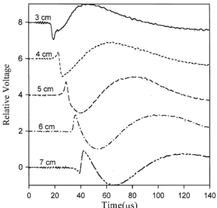
mentioned in the previous section. Shown in Fig. 5 are specimen was rested on a precision translation stage to
the waveforms of Lamb waves propagating normal to accurately control the distance between the source and
the fiber direction. The source–receiver distance was the receiver. An NBS conical transducer was utilized to
varied from 3 to 7 cm, i.e. from about 14 plate thick-measure the generated elastic wave signals from the
nesses to 30 plate thicknesses. For the case of source– laser sources. The received voltage signals from the
receiver distance equal to 3 cm, the measured waveform conical transducer were then amplified by a preamplifier
shows that the displacement signal is dominated by the and recorded by a digital oscilloscope. A trigger signal
lowest order antisymmetric mode. The dispersive nature synchronized with the laser source was utilized to trigger
of the signal is not very clear at this range. At the larger the digital oscilloscope. The recorded signals were sent
to a personal computer via GPIB. source–receiver distance, say 7 cm, the waveform shows
Fig. 4. The waveforms of Lamb wave in an anisotropic thin Cu plate.
Fig. 6. The waveforms of Lamb waves in the thin fiber-reinforced com-posite plate with propagating direction parallel to the fiber direction.
To understand the characteristics of Lamb wave propagation in different directions, we fixed the source– receiver distance at 6 cm and varied the propagation angle from 0° (parallel to the fiber direction) to 90° (normal to the fiber direction). The experimental results shown in Fig. 7 show clearly the evolution of the disper-sive nature of Lamb wave propagation direction from 0° to 90° in the thin fiber-reinforced composite plate.
5.2. Spectral analysis of Lamb waves
The phase difference w of two wave signals received at two different positions x1and x2 is equal to the phase
Fig. 5. The waveforms of Lamb waves in the thin fiber-reinforced com-posite plate with propagating direction normal to the fiber direction.
clear dispersive characteristics of the Lamb wave signal. From Fig. 5, one can find the evolution of the dispersive waveforms as a function of the source–receiver distance. Fig. 6 shows the waveforms of Lamb waves propagat-ing parallel to the fiber direction with the source–receiver distance varied from 3 to 7 cm. These waveforms show that the normal displacement of the Lamb wave is dominated again by the first order antisymmetric mode, however, the dispersive nature of the waves are not so clear as those of Fig. 5, in which the Lamb wave is propagating normal to the fiber direction. In fact, the waveform for the case of 7 cm source–receiver distance in Fig. 6 is similar to that of 3 cm source–receiver distance in Fig. 5. Therefore, we note that the Lamb wave needs a larger source–receiver distance to show
the dispersive nature when the propagating direction is Fig. 7. The waveforms of Lamb waves with propagation direction varied from 0° to 90° in the thin fiber-reinforced composite plate.
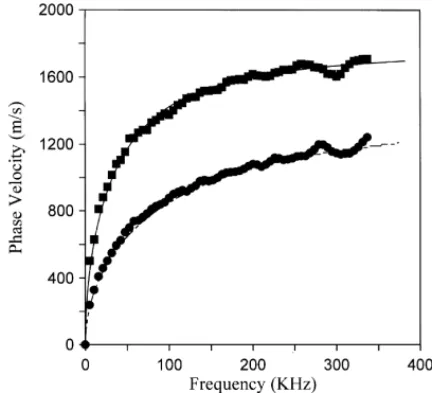
Fig. 9. Experimental dispersion of the antisymmetric Lamb waves Fig. 8. The frequency spectrum of the wave signal in Fig. 6 for the
case of source–receiver distance equal to 6 cm. propagating parallel (square symbols) and normal (solid circles) to the fiber direction.
angle of S
x1,x2, which is defined as: x
2-direction, it is easy to show that C11and C12do not
S
x1,x2( f )=R1( f )R12( f ). (8) appear in the Christoffel equation and hence the disper-sion relation either. Therefore, only the experimental In the above equation, R1( f ), R2( f ) are the fre- dispersion relation for a Lamb wave propagating along quency spectrum of the wave signals received at two
the fiber direction shown in Fig. 9 can be utilized to different positions x1and x
1, f is the frequency of the determine C
11and C12. harmonic wave, R1
2 denotes the complex conjugate of
R
2. The phase velocityv can then be obtained from the
relation: 6.1. Inversion scheme
n=2pfx1−x2
w . (9) between the measured (An error function which defines the div fference m) and the guessed (vg) phase velocities was defined as:
Fig. 8 shows the frequency spectrum of the wave signal in Fig. 6 for the case of source–receiver distance equal to 6 cm. The propagation direction of the Lamb
wave is along the fiber direction. The result shows that e= ∑ i=1 N [nm(i)−ng(i)]2 ∑ i=1 N [nm(i)]2 (10) the maximum frequency of the received signal is around
300 kHz. A similar result was obtained for the case of source–receiver equal to 4 cm. Utilizing Eqs. (8) and
where i represents the discrete non-dimensional wave (9), the dependence of the phase velocity of the Lamb
number and N is the number of data points utilized in wave on the frequency is shown by square symbols in
the inversion process. Fig. 9. The solid circles in Fig. 9 are the dispersion of a
In the inversion process, initial guesses of C11 and Lamb wave propagating perpendicular to the fiber
direc-C12 were made first, then the forward computer program
tion. We note that the experimental results reflect the
for calculating the phase velocity dispersion of a Lamb dispersion relations of the theoretical results shown
wave in a transversely isotropic plate was utilized to in Fig. 2.
calculate the guessed phase velocities (vg). The value of the error function can thus be obtained from Eq. (10). The true elastic constants, C11 and C12, were then
6. Inversion of anisotropic elastic constants
determined using the simplex method [17,18]. For the coordinate system shown in Fig. 1, we have
shown that C
33, C44and C55of a transversely isotropic 6.2. Inversion results material could be measured using conventional bulk
ultrasonics. The remaining unknown elastic constants The measured dispersion relation for Lamb waves propagating along the fiber direction shown in Fig. 9 are C
was utilized to determine inversely the elastic constants tional fiber-reinforced composite could be determined using a combination of the ultrasonic bulk wave and
C
11 and C12. Since there are two unknowns to be
determined, three initial guesses have to be made. To Lamb wave. Three out of five elastic constants of the specimen were obtained using the measured pure mode test the influence of the initial guesses on the inversely
determined results, four different sets of initial guesses bulk ultrasonic wave velocity. Dispersion of Lamb wave in the thin anisotropic specimen was measured and were used and the results are shown in Table 1. We note
that although the initial guesses of C
11 and C12 range combined with an inverse algorithm to obtain the rest of the elastic constants. We note that in the present from around 60%to 200%of the true values, the inverse
results converge nicely. The average values of the case, only dispersion for a Lamb wave propagating along the fiber direction is intimately related to the inversely determined constants C
11 and C12 are
C
11=134.45 GPa, C12=7.96 GPa. The standard devia- elastic constants C11and C12. In addition, experimental results demonstrated that the waveform for waves prop-tion of C11 is 0.17%of the average value, while that of
C
12is 2.4%. Therefore, on combining with those values agating along the fiber direction is very different from that of waves normal to the fiber direction. Finally, we measured by the ultrasonic bulk wave method, the
elastic constants of the unidirectional fiber-reinforced note that with this hybrid method, some of the aniso-tropic constants can be measured accurately with well-composite laminates are determined as:
developed bulk wave ultrasonics, while the rest of the undetermined elastic constants can be obtained from the inversion of the Lamb wave dispersion.
[C ij]=
C
134.45 7.96 7.96 0 0 0 7.96 11.38 5.15 0 0 0 7.96 5.15 11.38 0 0 0 0 0 0 3.11 0 0 0 0 0 0 4.99 0 0 0 0 0 0 4.99D
GPa. AcknowledgementThe authors are grateful for the financial support of this research by the National Science Council of China (11) through Grant NSC87-2732-E-002-002.
The solid lines in Fig. 9 are the dispersion relations calculated based on the elastic constants shown in Eq.
(11). We note that the experimental results are in References accordance with the theoretical predictions.
[1] R.M. Jones, Mechanics of Composite Materials, Scripta Book Company, Washington, 1975.
7. Conclusions [2] S.K. Datta, A.H. Shah, R.L. Bratton, T. Chakraborty, Wave propagation in laminated composite plates, J. Acoust. Soc. Am. 83 (6) (1988) 2020–2026.
Based on the results of this study, we demonstrated
[3] W.R. Rose, S.I. Rokhlin, L. Adler, Evaluation of anisotropic
that the anisotropic elastic constants of a thin unidirec- properties of graphite composites using Lamb waves, in: D.O.
Thompson, D.E. Chimenti (Eds.), Review of Progress in Quanti-tative Nondestructive Evaluation Vol. 6B, Plenum Press, New Table 1
York, 1986, p. 1111. Lists of the initial guesses and the inverse results of C
11and C12 [4] V. Dayal, V.K. Kinra, Leaky Lamb waves in an anisotropic plate. I: an exact solution and experiments, J. Acoust. Soc. Am. 85 (6) Guess C11(GPa) Guess C12(GPa) C11(GPa) C12(GPa)
(1989) 2268–2276.
[5] A.H. Nayfeh, D.E. Chimenti, Free wave propagation in plates of
222 6.0
anisotropic media, J. Appl. Mech. 56 (1989) 881–886.
298 4.5
[6 ] T.-T. Wu, S.-T. Chiu, On the propagation of horizontally
polar-254 5.5 134.2 7.7
ized shear waves in a thin composite laminate plate, Ultrasonics 30 (1) (1992) 60–64.
150 8.0
[7] J.F. Chai, T.-T. Wu, Determinations of anisotropic elastic
con-200 7.5
stants using laser generated surface waves, J. Acoust. Soc. Am.
220 7.2 134.8 8.2
95 (6) (1994) 3232–3241.
[8] M. Veidt, W. Sachse, Ultrasonic evaluation of thin
fiber-rein-135 7.8
forced laminates, J. Comp. Mater. 28 (4) (1994) 329–341.
140 7.2
[9] R.J. Dewhurst, C. Edwards, A.D.W. Mckie, S.B. Palmer,
Estima-148 6.8 134.3 7.8
tion of the thickness of thin metal sheet using laser generated ultrasound, Appl. Phys. Lett. 51 (14) (1987) 1066–1068.
110 8.8
[10] D.A. Hutchins, K. Lundgren, A laser study of transient Lamb
120 8.6
wave in thin materials, J. Accoust. Soc. Am. 85 (4) (1989)
104 9.2 134.5 8.0
[11] H. Nakano, S. Nagai, Laser generation of antisymmetric Lamb [15] A.N. Stroh, Steady state problems in anisotropic elasticity, J. Math. Phys. 41 (1962) 77–103.
waves in thin plates, Ultrasonics 29 (1991) 230–234.
[12] S.E. Bobbin, J.W. Wagner, R.C. Cammarata, Interpretation of [16 ] M.B. Braga, Wave propagation in anisotropic layered composites, Ph.D. dissertation, Stanford University, 1990.
laser generated low-order Lamb waves for elastic modulus
meas-urements in thin films, Ultrasonics 30 (2) (1992) 87–90. [17] J.A. Nelder, R. Mead, A simplex method for function minimiza-tion, Comput. J. 7 (1965) 308–313.
[13] B.A. Auld, Acoustic Fields and Waves in Solids Vol. 1, Wiley
Interscience, New York, 1973. [18] T.-T. Wu, Y.-H. Liu, Inverse analyses of thickness and elastic properties of a bonding layer using laser generated surface waves, [14] R.L. Weaver, Y.H. Pao, Axisymmetric elastic waves excited by a