DESIGN AND IMPLEMENTATION OF A SENSORLESS
SWITCHED RELUCTANCE DRIVE SYSTEM
**Bin-Yen Ma, *Tian-Hua Liu, *Ching-Guo Chen, *Tsen-Jui Shen, and **Wu-Shiung Feng *Department o f Electrical Engineering
National Taiwan Institute o f Technology 43, Keelung Road, Section 4
Taipei, Taiwan 106, R. 0. C.
A b s t r a c t This paper presents a new sensorless switched reluctance drive system. By suitably shaping a n induced voltage in a n inactive phase which is adjacent to an energized phase o f a switched reluctance motor, the shaft position o f the rotor can b e easily obtained. First, the theoretical analysis o f the proposed method is presented. By systematic theoretical analysis, a voltage signal which can easily estimate the shaft position o f the motor is derived. This signal is only related to the input dc voltage o f the converter, and the self and mutual inductances o f the motor. After that, the design for a simple circuit which can synthesize the required voltage signal f o r rotor position estimation is presented. Next, how a 32-bit microprocessor system is used t o execute the position and speed estimation, speed-loop control, and current-commands generation is shown. Several experimental results validate the theoretical analysis. This paper presents a new direction in the design and implementation o f a sensorless switched reluctance drive system.
...
This research is supported by the National Science Council, R. 0.C.
under grant NSC 86-2213-E- 01 1-076.**Department o f Electrical Engineering National Taiwan University
1, Roosevelt Road, Section 4 Taipei, Taiwan 106, R. 0. C.
1. INTRODUCTION
Switched reluctance motor (SRM) drive technology has been developed over the last two decades. The SRM system has many advantages. For example, both the motor configuration and the power converter are simple and rugged. There is no winding in the rotor. As a result, the SRM has a higher efficiency than the induction motor [ 11. The sensorless drive is a new direction in the design and implementation o f the SRM drive system. Papers on several techniques in this field have been published. For example, Lang e t al. proposed state observers t o determine the rotor position o f the SRM. These observers, however, were only validated by computer simulations [2]. Another way to obtain the position information is t o detect the phase current waveform and determine the position by calculating the phase inductance value from the changing rate o f the phase current [3]. This method, however, requires injection o f a diagnostic pulse t o a n inactive phase. This diagnostic pulse generates negative torque and reduces the performance o f the drive system. Some researchers have used different approaches t o estimate the rotor position of t h e SRM. Ehsani e t al. proposed a linear inductance t o
time period converter in order t o estimate the shaft position [4]. Though this approach i s good and direct, a modulated circuit is required. The modulated circuit i s difficult t o realize and the signal is easily polluted by the pulse-width- modulated (PWM) switching voltage a s well. Recently, a sensorless method h a s been proposed by measuring a mutually induced voltage of a n inactive phase o f the SRM [ 5 ] . This is a n effective way t o estimate the shaft position o f the SRM because i t provides a clear relationship between the induced voltage and the rotor position. This method, unfortunately, h a s some disadvantages also. First, this method requires the design o f a sample and hold circuit which is controlled by a synchronizing signal. The signal h a s t o be synchronized with the PWM signals o f the converter t o detect whether the energized winding is operated in a conduction mode
or in a free-wheeling mode. The circuit, therefore, is difficult t o implement. Second, after the sample and hold circuit, the mutually induced voltage i s related t o t h e current command, the stator resistance, the mutual inductance, the self- inductance, and the rotor speed o f the switched reluctance motor. The proposed sensorless method in paper [ 5 ] , therefore, h a s some limitations. For example, a t a low speed control range, a three- dimensional table is required even under the assumption that the speed dependent terms are negligible. I n addition, the proposed method can not be applied in a high speed range becaus-e the speed dependent terms enlarge t h e estimated position error. I n t h i s paper, we, therefore, propose a new method f o r solving the above mentioned problems.
2. SYSTEM DESCRIPTION
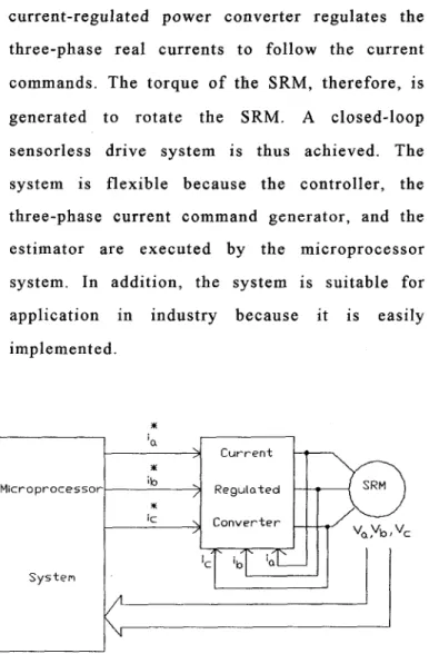
Fig. 1 shows the proposed closed-loop control diagram o f the whole SRM drive system. The system consists o f two major parts: a microprocessor system and some hardware circuits. The microprocessor system consists of a 32 bit CPU
( MC68020), a coprocessor ( MC68881), D/A converters, and AID converters. The coprocessor can efficiently compute sin, cos, and floating point operations. Moreover, the MC6888 1 executes its computation concurrently with the MC68020 t o reduce the required computation time o f the whole system. The sampling interval o f the microprocessor system, therefore, is only 0.4 ms. The hardware circuits consist of some Hall-effect current sensors, a rectifying circuit, a shaping circuit, a current regulated converter, and a three- phase, 10 hp, 12/8 SRM. In the closed-loop drive system, first, the microprocessor reads the shaped mutual induced signal V,no of each phase via the AID converter, and estimates the shaft position and speed o f the SRM. Second, the microprocessor calculates the speed difference between the speed command and the estimated speed. Third, the microprocessor executes the speed-loop controller t o determine the torque command
T,
* . Next, the microprocessor maps the torque command t o the current command amplitudeI * .
After that, the microprocessor determines the three-phase current commandsI,
* ,I,,
* , andI ,
* according to an estimated commutation angle 8 , . The three-phase current commands are square wave with 1/3 duty cycle. Finally, the microprocessor outputs the three-phase current commands t o a current-regulated converter via the DIA converters. The current-regulated power converter regulates the three-phase real currents t o follow the current commands. The torque o f the SRM, therefore, is
generated t o rotate the SRM. A closed-loop
sensorless drive system is thus achieved. The system is flexible because the controller, the three-phase current command generator, and the estimator a r e executed by the microprocessor system. In addition, the system is suitable for application in industry because it is easily implemented. 3 i
>
C u r r e n t>
R e g u l a t e d ic>
C o n v e r t e r Y ib M i c r o p r o c e s s o r 3 SystemFig. 1 Block diagram o f the whole system.
3. SENSORLESS TECHNIQUE
In this paper, a circuit t o detect the mutual induced voltage of the stator winding, which is inactive and in front of the currently energized winding, is designed. For example, i f the b-phase is
energized, the mutual induced voltage of the a-
phase is detected t o determine the commutation angle (time) o f turning o f f the b-phase a s well a s turning on the c-phase. This principle can be easily
applied while the c-phase or the a-phase is
energized. The systematic theoretical analysis is
described a s follows. The induced voltage o f the mutual inductance for a SRM can be expressed a s
A,=
L,
i
(2)where V , is the induced voltage,
A,
is the mutual flux-linkage,L,
is the mutual inductance, and i is the energized current. Substituting ( 2 ) into ( l ) , w e can obtainv , = L , d i / d t + o ,
i
d L,/d
8 ,
( 3 )where W e is the electrical rotor velocity o f the motor. The energized voltage can be expressed a s
where
vph
is the energized phase voltage,r
is the stator resistance,h,
is the self-induced flux, andL,
is the self-inductance. According t o equation (4), we can easily obtaind i l d
t = ( l / L s ) ( V p h- i
r - w e
i
d
L s / d 8 , )
( 5 )
After substituting equation ( 5 ) into equation ( 3 ) , we can obtain
v , = ( L , / L , ) ( v p h
- ir - m e
i
d L s / d 8 ,
)+ w e
i
d L,/d
8 ,
( 6 )The induced voltage is related t o the switching mode o f the energized winding. Fig.
2
shows the configuration of one leg o f the converter. Then, wediscuss the operation o f the adjacent energized phase in Fig. 2. While the power devices and
T2
are conducted , the stator winding i s operated in a conduction mode. In this mode, the phase voltagevPh
o f the measured winding i s equal t o the input dc supply voltageV,.
The induced voltage, therefore, can be expressed a sv,,=(
L,IL,)( Vd,-
ir
- w e
i
d L,/d
8 ,
)+ w e
i
d L,id
8 ,
( 7 )wherev,, is the mutual induced voltage while the adjacent phase is operated i n a conduction mode. On the other hand, while the adjacent energized phase is operated in a free-wheeling mode, its power devices
7;
a n dT2
are turned off. Then the diodesDl
andD2
are turned on immediately t o maintain the current o f the winding a s a constant. Therefore, the phase voltagevPh
is equal t o-VdC.
The induced voltage can b e expressed a svmf
=(L,/Ls)(-vdc- i r - w e
i d L,ld
8 , )
+ w e
i
d L,id 8 ,
( 8 )wherevmf is t h e mutual induced voltage while the adjacent energized phase i s operated in a free- wheeling mode. From equation (S), i t is easy t o understand that the voltage
vmf
is always negative because the last term is small. As a result, we can design a rectifier circuit t o change the polarity o f the voltagev m f .
After the process o f the rectifier circuit, the induced voltage becomes a positive value, and is expressed a sv,,=(
L,l Ls>(
V,+
i
r
+ w e
id
L,id 8 ,
)-
CO,
i
d
L,id
8 ,
(9)where
v,,
is the signal of the rectified mutual induced voltage while its adjacent phase i s operated a t a free-wheeling mode. Observing the equations( 7 ) and ( 9 ) , the last three terms can be canceled by
using a smoothing or averaging circuit. Many different circuits can provide this function. In this paper, a passive filter is designed to eliminate the high frequency harmonics and t o smooth (average) the
v,,
andv,,. The voltage a t the output o f the filter can be expressed approximately a swhere
v,,
is the output voltage of the filter. The equation (10) is very attractive because the induced voltage at the output of the filter is only related t o the input dc voltage of the converter, and the self and mutual inductances of the SRM. In addition, these inductances are related t o the rotor position of the SRM. The rotor position of the SRM, therefore, can be easily estimated by detecting the output voltage of the filter.Fig. 2 The measuring and shaping circuit o f the induced voltage.
4. EXPERIMENTAL RESULTS
Some experimental results a r e shown here. While we executing the experiment, the SRM is coupled with a dynamometer, TM-5MT (DS), which is a product o f the MEIWA company. The experimental waveforms a r e measured by a Tektronix digital storage oscilloscope-TDS 4 10.
The parameters o f the speed control a r e
Kp=3
andK,=O.Ol.
The input voltage o f the converter isCc=
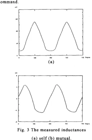
150 V. The inertia o f the motor and dynamometer is 0.025 Nt-m- s e c L / r a d . The hysteresis band is set atk 0 . 3 A. Some simulated and experimental results are shown here. Fig. 3(a) shows the calculated self-inductance o f the SRM
.
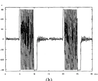
Fig. 3(b) shows the measured mutual inductance which is obtained by exciting a 2 A constant current and then computing the mutual inductance. Fig. 4(a) is the measured a-phase voltage waveform that is detected a t the output o f the isolation amplifier circuit o f the a- phase. The measured waveform is switched between positive and negative because each leg o f the power converter is operated between the conduction mode and the free-wheeling mode. From 0 to 30 degrees, the a-phase is energized by the PWM input voltage. However, due t o the falling time o f the current, the energized voltage is maintained continuously from 0 to 50 degrees. Beyond 50 degrees, the a-phase is blocked and the b-phase is energized. After that, the measured voltage is not a n energized PWM voltage but is the induced voltage o f the a-phase while the b-phase is excited. Fig. 4(b) shows the waveform that has been processed by the rectifying and filtering circuits. I n this figure, the waveformis a smoothing wave. Beyond 50 degrees, the signal is a n induced voltage which is related t o the rotor position. The setting voltage level and the signal are crossed at 150 degrees. At this point, the b- phase is blocked, and the c-phase is energized. As a result, we detect the a-phase induced voltage t o determine the commutation time o f turning o f f the b-phase and turning on the c-phase. Fig. 5 shows the rotor angles o f the estimated angle and the real angle, which is detected by using an encoder. Fig. 6(a) shows the measured speed response o f a 500
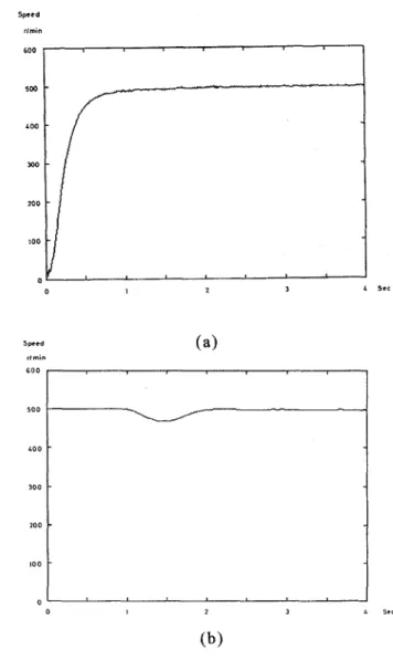
r/min step input command, Fig. 6(b) shows the load disturbance rejection response o f the system a t 500 r/min and 2 Nt-m. Fig. 7 shows the correspondent (500 r/min, 2Nt-m) steady-state a-phase current and a-phase voltage. Fig. 8 shows the speed response of the system at a 50 r/min step input command.
m *
n"
'
T
I
Fig. 3 The measured inductances (a) self (b) mutual.
Vm,3 V 15 1c I 600 500 400 300 200 100 0 E n e r g t a d R q i o n 3 Induced Region - -
-
- IO 60 90 120 150 ita Degree (b)Fig. 4 The measured induced voltage
(a) before rectifying (b) after filtering
.
360
180
0
0 20 40 €4 80 100 m r
Fig. 5 The estimated and real rotor angle.
0 1 2 3 4 s e c
~ (a) transient (b) load disturbance.
&
0 5 IO 5 20 1 5 30 m s ( b )
Fig. 7 The measured steady-state waveforms (a) a-phase current ( b ) a-phase voltage.
4 0 0
~~
1 . o 2.0 3 . 0
T i m e (sec1
Fig. 8 The measured speed response o f the sensorless drive a t 50 rlmin.
5. CONCLUSIONS
In this paper, a simple method of designing and implementing a sensorless switched reluctance drive system has been presented. By designing a simple circuit, the commutation angle o f the SRM
has been easily determined. Then,
a
microprocessor based sensorless SRM drive has been implemented. The sensorless drive system performs well. Several experimental results show the feasibility and correctness o f the proposed sensorless method. The method proposed in this paper can easily be applied to actual industrial use due t o its simplicity. This paper presents a new direction in the design of a sensorless switched reluctance drive system.REFERENCES
[ 11 T. A. Lipo, “Recent progress in the development o f solid-state ac motor drives,” IEEE Trans. on
Power Electron., vol. 3 , no. 2, pp. 105-117, Apr. 1988.
[2] A. Lumsdaine and J . H. Lang, “State observers for variable-reluctance motors,” IEEE Trans. on Ind. Electron., vol. 37, no. 2, pp. 133-142, Apr. 1990.
[3] W. D. Harris and J. H. Lang, “A simple motion estimator for variable- reluctance motors,” IEEE Trans. on Ind. Appl., vol. 26, no. 2, pp. 237-243, Mar./Apr. 1990.
[4] M. Ehsani, I. Husain, and A. B. Kulkarni, “Elimination o f discrete position sensor and current sensor in switched reluctance motor drives,” IEEE Trans. on
no. 1, pp. 128-135, Jan./Feb. 1992.
Ind. Appl., vol. 28,
[5] I. Husain, M. Ehsani, “Rotor position sensing in switched reluctance motor drives by measuring mutually induces voltages,” IEEE Trans. on Ind. Appl., vol. 30, no. 3, pp. 665-672, May/ June 1994.