Triangularly phase-modulated optical fiber ring
resonator sensor
Pie-Yau Chien and Ci-Ling Pan
An optical fiber ring resonatory sensor system has been demonstrated by applying a triangular phase modulation signal to a fiber loop. The dynamic range for detection of optical phase change is 27r. The sensor is linear within this range. The minimum detectable optical phase change is 1.5 x10⁻⁴ rad/Hz1/2.
Key words: Fiber resonator, sensor, signal processing.
I. Introduction
The optical fiber ring resonator has been extensively studied by many workers for a number of years.1-14 This optical device has been used for sensor applica-tions,7 laser-diode frequency stabilization,8 and in fiber-optic gyroscopes.9-'4 In these applications, in order to obtain a highly sensitive output signal for a given change in the optical path length or laser frequency, the linewidth of the resonator is in general the most important parameter. The intensity varia-tion at the maximum sensitive posivaria-tion of the trans-mittance of the resonators8or a differential S-shaped output signal obtained at the resonance frequency9 has been used to extract information on the change in optical phase delay. The ring resonator is more sensitive than Mach-Zehnder-type interferometers, but its dynamic range and linearity characteristics are limited by the resonator linewidth and thus are inferior to Mach-Zehnder-type interferometers. To alleviate this problem, one can employ the so-called closed-loop configuration often used in fiber-optic gyroscopes.1 0-14 In this method, two acousto-optic modulators operated as frequency shifters are used to tune the laser frequency to the peak position of the resonance curve. The optical phase change is then nulled by tuning the laser frequency. The dynamic range and the linearity of the discrimination curve is then no longer limited by the FWHM linewidth of the ring resonator, but by the maximum tuning range of the laser frequency. Recently, we demonstrated a
The authors are with the Institute of Electro-Optical Engineer-ing, National Chiao-Tung University, Hsinchu, Taiwan 30050, China.
Received 18 September 1990.
0003-6935/92/ 152776-04$05.00/0.
© 1992 Optical Society of America.
frequency stabilizer for a set of laser diodes by applying a triangular phase modulation signal to a bulk Fabry-Perot interferometer followed by a time-gating techniques for signal processing. Because of a linearly scanned optical phase delay by a triangular waveform, the dynamic range of the frequency dis-criminator is thus improved. In this paper we apply this technique to signal processing in a fiber ring resonator. It is shown that the linearity and dynamic range of the sensor system are improved significantly. In Section II the basic principle of our approach is described. The experimental method is discussed in Section III. Finally, experimental results are
pre-sented and discussed in Section IV.
II. Basic Principles
A fiber-optic ring resonator interferometer is simply a ring section of a single-mode fiber with a fiber coupler exhibiting a highly unbalanced coupling ratio. The free spectral range (FSR) of the resonator is cinLo, where Lo is the length of the ring resonator and n is the refractive index of the fiber core. Its characteris-tics are similar to a bulk Fabry-Perot interferometer in which the reflectedp'ower exhibits sharp minima at resonance. The relation between the output intensity
IJ nad the input intensity I of a fiber-optic ring
resonator can be expressed as'
= (1 - -y)
x |-(1 -Kr)/[( + Kr)2-4Kr sin2(3L/2- /4)}, (1)
where y0 and Kr are, respectively, the fractional loss
and the coupling coefficient of the fiber coupler. Under the condition that
13L
= m(2wr) - r/2, suchthat sin2[(QL/2 - r/4)] = 1 in Eq. (1), the output
intensity of the fiber resonator is then at its mini-mum.
To sense the change in fiber length, we applied a triangular phase modulation signal to a fiber-coiled piezoelectric transducer (PZT) in the fiber loop, so that the optical phase delay is swept linearly as shown in Fig. 1. The amplitude of the triangular waveform is adjusted such that the sweeping range is equal to one FSR. The output of the resonator contains one spec-tral line corresponding to that of a single-mode laser within the sweeping time, as shown in Fig. 1(b). If the resonance condition is further satisfied, the optical phase delay within the two half-periods of the triangu-lar waveform can be expressed as
p+=(L + L + yt) = 2mir, -T/2 < t < 0, (2a)
and
4_ (L + L - yt) = 2m7r, 0 < t < +T/2, (2b)
where Lo is the bias fiber length;
L
is the change infiber length to be measured; b -PLO; Us f3Ll; y is
the slope of the triangular waveform; and m = 0, 1, 2,
3.... By differentiating between Eqs. (2a) and (2b)
with respect to L and t, we can derive the positions of
the spectral lines in the time domain. These are
At+ = -ALs /y -T/2 < t < 0,
At_ = +ALs/y, 0 < t < +T/2. (3b)
The time intervals, At+ and At_, can be detected, respectively, by the gate-switching technique.'5 The temporal separation of these lines in the two half-periods of a triangular waveform is
Atd = At+ - At-I = 2AL/ly. (4)
2T7
T l.5T 0 0.5T T T 0.5 T 0 0.5T T T 0.5T t- 0 t. 0.5 T T I St _1
1 b=tb
Gi G 2 Gi G2 I I T 0.5T 0 0.5T TIt follows that the path-length change, AL,, can be measured directly from the time difference, Atd. This can be measured either from the analog output of a phase meter or digitally by using a gated counter. Since Atd is linearly related to the optical phase change within the full 2r rad phase range, the full FSR of the resonator is available for measurement in our system. In contrast, the region that can be used for path-length measurement in conventional meth-ods7-9 is equal to the FWHM of the resonance curve, which is inversely proportional to the finesse.
III. Experimental Method
Our experimental setup is shown in Fig. 2. The light
source was a single-mode laser diode (Hitachi Model
HLP1400, = 0.83 [Lm), for which the driving cur-rent and operating temperature were both stabilized
such that AI0/10 < 1.0 x 10⁻⁵ and AT < 1.0 x
10-30C.
An optical fiber ring resonator loop was constructed with an adjustable fiber coupler and a fiber section. Nonpolarization-maintaining, single-mode, 30-cm long fiber was used in this experiment. By adjusting the coupling ratio of the adjustable fiber coupler, we obtained a finesse of 70 for our resonator. Two in-line fiber polarization controllers (PC's), one placed at the input port of the fiber coupler and the other located in the fiber loop, were used such that the fiber loop operated in the true single polarization mode. Two
fiber-coiled piezoelectric transducers, PZT1 and PZT2,
were used for signal processing. The PZT1 was used to sweep linearly the optical phase delay at 30 kHz and stabilize the operation bias points. The PZT2 was used to simulate a change in fiber length for system performance test. The amplitude of the triangular waveform applied to PZT1 was adjusted such that only one spectral line was observed in each of the two half-periods of the triangular waveform. This output signal was then gate switched to select the spectral lines in the two half-periods. The time difference between these two gated output signals was then compared at the phase meter. The optical path length
t (a) 0 PC F C PD t(b)
I_
IVI
i' X t (C)Fig. 1. Operating principle of the triangular phase-modulated fiber ring resonator sensor: (a) triangular phase modulation
wave-form; (b) corresponding spectral lines in positive- and negative-sloped regions of the triangular waveform, where db L, and As
= iL,; (c) gate-switching signal for spectral line selection.
I O/P
Fig. 2. Experimental setup: LD, laser diode; 0, objective lens; PC, polarization controller; FC, fiber coupler; PD, photodetector; PZT,
piezoelectric transducer; PI, proportional and integrating circuit.
20 May 1992 / Vol. 31, No. 15 / APPLIED OPTICS 2777
\,///.\
\0-.
I
I
1
can be detected by measuring the time delay or the phase difference of these gated signals.
IV. Results and Discussions
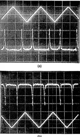
The output signals of the fiber ring resonator at the
photodiode are shown in Figs. 3(a) and 3(b) for different path-length differences. It is clear that the change in optical phase delay manifests itself as different time delay positions. In order to eliminate the low-frequency, environmentally induced optical phase noise, the output signal of the phase meter at a frequency lower than 1.0 kHz was used for stabiliza-tion of the operastabiliza-tion bias point. To achieve this, the output signal of the phase meter was sent through a proportional and integrating (P + I) circuit and then applied to PZT1. In order to achieve the maximum possible dynamic range of the sensor output, the bias point of the ring resonator can be stabilized such that the spectral lines are located at the central positions of the two sweeping half-periods. This can be achieved by controlling the fiber length, e.g., the spectral line located at T14 for the positively ramped modulation signal and -T14 for the negative ramped modulation singal. For measurement of the time difference, Atd, a gating signal can be generated from the triangular waveform and used to select the two spectral lines located on the positive-sloped and negative-sloped
(a)
t=T l=211 2
,- Servo Loop Closed
tbT *= T
4
-II- -t
1Imin
IUl11111111 11 111 tO =0
Fig. 4. Phase meter output with a feedback loop for operation bias point stabilization under free-running and closed-loop conditions. The optical phase delay is stabilized at = 7 'r, corresponding to a time delay of tb = T/4.
regions of the triangular waveform as shown in Fig. 1(c). The time difference can then be read out by a phase meter at the output of the gate switches. In our
system, the servo bandwidth was selected to be 1.0 kHz, the optical phase bias, Hub, of the phase delays,
4+
and
_,
has been stabilized to Ab 1.5 x 10⁻⁴rad/Hzl/2. Following Eqs. (2)-(4), we find that the corresponding timing jitter is Atd < 0.36 ns as predicted by Eq. (4). The minimum detectable fiber
length change is ALmin = (4b,mi X X)/(n x 2 T) _ 1.3
nm, where X is the wavelength of the laser diode and n is the refractive index of the single-mode fiber. This result is shown in Fig. 4 for the free-running and closed-loop situations.
The linearity of the system response is influenced by the linearity of the PZT. At the turning point of the triangular waveform, high frequency harmonics
of the modulation signal are present, and the fre-quency response of the PZT may not be high enough to respond. This problem can be eliminated by modify-ing the duty cycle of the gate-switchmodify-ing waveform such that the nonlinear region is gated out. If the temperature of the fiber loop is also stabilized, this
Deg - 40* All 35. a 30 25 0 2: 2 0 0 _r_ 1 5 1 0 5 180 0 1 0 20 30 40 50 60 70 80 mV (b)
Fig. 3. (a), (b) Photodiode output signals for two different optical
phase biases. The upper trace represents the detected signal; the lower trace represents the applied triangular phase modulation signal. The peak-to-peak voltage of the triangular waveform is 1.2
V and its frequency is 30 kHz.
Driving Voltage
Fig. 5. Phase meter output as a function of the amplitude of a 5-kHz sinusoidal waveform applied to PZT2. The relation between the phase meter output 0 and the temporal separation Atd of the spectral lines in the two half-periods of the triangular waveform is 00 = (360'/T) Atd, where T is the period of the triangular
waveform.
2778 APPLIED OPTICS / Vol. 31, No. 15 / 20 May 1992
..
~~~~~~~~~~~~~~~...
"I1
I I I I
system can be used as the frequency discriminator of the laser diode. The long-term frequency stability achievable, however, is influenced by the change and slow drift in the PZT response. The frequency discrim-inating characteristics of our approach were obtained from the symmetrical positions in the two half-periods of the triangular waveform. Thus common mode noise rsulting from the PZT can be partially eliminated. Figure 5 shows the result of the scale factor linearity of the sensor system with a 5.0-kHz modulation signal applied to PZT2.
IV. Conclusion
We have demonstrated a novel technique for signal processing in fiber ring resonator sensors, based on a triangular phase modulation waveform. The change in optical path length was measured by the time difference between the positions of the spectral lines in two half-periods of the triangular signal. The minimum detectable optical phase delay was 1.5 x
10-4 rad/Hzl/2. The dynamic range in the phase delay
of the system is 2ir rad.
This work was partially supported by the National Science Council of the Republic of China under grant NSC-80-0417-009-05.
References
1. L. F. Stokes, M. Chodorow, and H. J. Shaw, "All-single-mode fiber resonator," Opt. Lett. 7, 288-290 (1982).
2. E. J. Bachus, R. P. Braun, and B. Strebel, "Polarization
maintaining single-mode-fibre resonator," Electron. Lett. 19,
1027-1028 (1983).
3. L. F. Stokes, M. Chodorow, and H. J. Shaw, "All-fiber
stimu-lated Brillouin ring laser with submilliwatt pump threshold,"
Opt. Lett. 7, 509-511 (1982).
4. E. Desurvire, M. J. F. Digonnet, and H. J. Shaw, "Theory and implementation of a Raman active delay line," IEEE J. Lightwave Technol. LT-4, 426-443 (1986).
5. E. Desurire, A. Imamoglu, and H. J. Shaw, "Low threshold synchronously pump all fiber ring Raman laser," IEEE J. Lightwave Technol. LT-5, 89-96 (1987).
6. M. V. Andres and K. W. H. Foulds, "Optical-fiber resonator
rings based on polarization-dependent coupler," IEEE J. Lightwave Technol. 8, 1212-1225 (1990).
7. L. F. Stokes, M. Chodorow, and H. J. Shaw, "Sensitive all
single-mode fiber resonant ring interferometer," IEEE J. Lightwave Technol. LT-1, 110-115 (1983).
8. S. Tai, K. Kyuma, and T. Nakayama, "Spectrum linewidth of an external cavity laser diode stabilized by a fiber ring resonator," Appl. Phys. Lett. 47, 91-93 (1985).
9. M. Ohtsu and S. Araki, "Using a 1.5-pim DFB InGaAsp laser in
a passive ring cavity-type fiber gyroscope," Appl. Opt. 26, 464-470 (1987).
10. R. E. Meyer, S. Ezekiel, D. W. Stone, and V. J. Tekippe,
"Passive fiber-optic ring resonator for rotation sensing," Opt.
Lett. 8, 644-646 (1983).
11. Y. Ohtsuka, "Analysis of a fiber-optic passive loop resonator
gyroscope: dependence on resonator parameters and light source coherence," IEEE J. Lightwave Technol. LT-3,
378-384 (1985).
12. K. Iwatsuki, K. Hotate, and M. Higashiguchi, "Effect of Rayleigh backscattering an optical passive ring-resonator gyro," Appl. Opt. 23,3916-3924 (1984).
13. K. Iwatsuki, K. Hotate, and M. Higashiguchi, "Kerr effect in an optical passive-resonator gyro," IEEE J. Lightwave Tech-nol. LT-4,645-651 (1986).
14. K. Iwatsuki, K. Hotate, and M. Higashiguchi, "Backscattering in an optical passive ring-resonator gyro: experiment," Appl. Opt. 25, 4448-4451 (1986).
15. P. Y. Chien and C. L. Pan, "Relative frequency stabilization of
a set of laser diodes using the time-gating technique," Opt. Commun. 83, 81-84 (1991).