Spatial-domain image hiding using image
differencing
D.C.Wu and W.H.Tsai
Abstract: A method to embed a secret image into a cover image is proposed. The method is based on the similarity among the grey values of consecutive image pixels as well as the human visual system’s variation insensitivity from smooth to contrastive. A stego-image is produced by
replacing the grey values of a differencing result obtained from the cover image with those of a differencing result obtained from the secret image. The process preserves the secret image with no loss and produces the stego-image with low degradation. Moreover, a pseudorandom mechan- ism is used to achieve cryptography. It is found from experiment that the peak values of signal-to- noise ratios of the method are high and that the resulting stego-images are imperceptible, even when the size of the secret image is about a half of the cover image.
1 Introduction
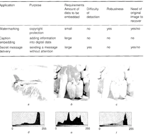
Most text, image, audio, and video data can be represented in digital form. Owing to the human visual system’s low sensitivity to small changes and the high plasticity of digital media, one can easily make small changes in digital data with low perceptibility, or even produce new data by mixing different data sources. Consequently, many inter- esting applications of data hiding in digital media can be created, like watermarking, caption data embedding, secret message delivery, etc. The purposes and requirements of the applications vary and are illustrated in Table I .
Several previous works about data hiding in document images have been discussed in [ I , 21, such as line-shift coding, word-shift coding, feature coding, etc. The quan- tity of the embedded data is small and can be easily destroyed by reproduction. In the fields of data hiding in images, the method of changing least significant bits (LSBs) [3, 41, the patchwork method [5], and the tcxture block coding method [2] all use the low sensitivity of the human visual system to small changes in grey values to embed data in the host image. Data hiding in images can also be conducted in the frequency or other transform domains. Such methods can embed a small amount of information in images with robustness: examples are the use of randomly sequenced pulse-position modulated codes [6], the secure spread spectrum method [ 7 ] , wavelet-based embedding methods [8, 91, and DCT- based embedding methods [lo, 111. Incidentally, some terms about information hiding found in [ 121 are followed in this study.
:(: IEE, 2000
ZEE P m x w l i n g s online no. 20000104
Dol: 10.1049/ip-vis:20000104 Paper received 27th July 1999
The authors are with the Department of‘ Computer and Information Seicnce, National Chiao Tung Univcrsity, Hsinchu, Taiwan 30050, Republic of China
D.C. Wu is also with the Dcpartmcnt of’ Information Management, Ming Chuan University, Taipei, Taiwan 1 1 I , Republic of China
IEE Proc.-Vcs. hncige Signal Process., h[. 147, No. I , Febrllory 2000
We propose a new method to embed a grey-valued image into a grey-valued cover image. It can be used for delivering secret images such as confidential images, military maps, etc. The method is designed in such a way that the grey value of every pixel of the secret image is preserved, i.e. no distortion will be created in the secret image when it is extracted out from the stego- image. On the other hand, because the resulting stego- image usually contains a large quantity of embedded data, it may be degraded seriously. The proposed method, however, produces imperceptible changes in the resulting stego-image. Because the precision of pixel grey values may be destroyed when transforming them back and forth between the frequency and spatial domains, we adopt a way o f embedding the secret image into the cover image directly in the spatial domain. Since a large quantity of data is directly embedded in the spatial domain, our method is not robust against most image transformations, such as lossy compression, cropping, etc. This is a common problem of the LSB-like methods.
The grey value replacement method proposed by Liaw and Chen [ 131 embeds a secret image into a cover image byte after byte by finding for each pixel p in the secret
image a pixel p’ in the cover image whose grey value g’ is
close to that (say, g ) o f p and then replacing g with g’. This
method suffcrs from a problem: in certain images with different histogram shapes (Figs. Id and le), there might exist many pixels in the secret image which do not have suitable pixels in the cover image with similar grey values to allow grey value replacement. To create suitable pixels for replacement, an adjustment method was performed firstly on the pixel values of the cover image. The effect of the result is similar to that of the method of histogram specification [ 141, which adjusts the shape of the histogram of the cover image to match that of the secret image. As shown in Figs. I C and Figs. 1J; the resulting cover image may have serious distortion after the adjustment. In such a case, it is impossible to produce a stego-image without noticeable changes. The method proposed in this paper may be instead employed to embed an image into a cover image easily, and changes in the cover image after embed- ding are imperceptible to casual views. Moreover, during the work of data hiding we walk through the cover image in
Table 1: Applications of data hiding in digital media
Application Purpose Requirements
Amount of Difficulty Robustness Need of
data to be of original
embedded detection image to
recover Watermarking copyright
protection Caption adding information embedding into digital data Secret message sending a message delivery without attention
~ ~~
small no Yes yesino
large no no no
large Yes no yesino
a b
e
c Restilt after perfonning histogram specification to ‘Peppcrs’ according to histogram of ‘Jet’
d Histogram 01‘ ‘Jet’ e Histogram of ‘Peppers’
,fHistogram of resulting ‘Peppers’ aftei- perlht-niiiiS histogram specification
an order provided by a pseudorandom number generator to achieve cryptography, and so tampering access to the hidden data from illicit users can be prevented.
2 Proposed
image hiding method
The method utilises the property of grey-value similarity among adjacent pixels which exists in most natural images (i.e. images not created by computers). The grey-value differences of adjacent pixels in quite different natural images may have probability density fiinctions with very similar shapes. As an illustration, see the 256 grey-valued images of ‘Jet’ and ‘Peppers’ in Figs. 1u and IO, respec- tively. The histograms of these two images are shown in Figs. Id and le, respectively. They are quite different in shape. Now, perform the operation of ‘image differencing’ to the two images in the following way: for every pixel value g j in either image I , where i = 1, 2 , . . . , let
gj’=gj - gip,
+
128 where gip, is the grey value of aneighbouring pixel to g j , and create a new image I‘ with all gi’ as the new pixel values. Call I’ the difference image from I. More details of image differencing in our proposed method, which are a little different from that just shown, are in the following section. The difference images from ‘Jet’ and ‘Peppers’ are shown in Figs. 20 and 2h, respec-
tively, and their histograms are shown in Fig. 2c and 2 4
respectively. The pixel values of the difference images are concentrated near 128 resulting from the grey-value simi-
30 C 0 f a 0 255 C Fig. 2 D(ffer.cwce imugiiig (I Difference image of‘ ‘Jzt’
/ I Difference i i n a ~ e of ‘Peimers.’ 255 b 0
--
I_...
255 d . Ic Hihtogram of difference image of ‘Jet‘
r l Histogram of diffci-ence ~mage of ’Peppers’
larity between adjacent pixels. The histograms of the difference images are quite similar in shape, in contrast with those of their original images, which are quite different. The similarity helps us exploit a way to embed a secret image easily by grey value replacement using a difference cover image and a difference secret image.
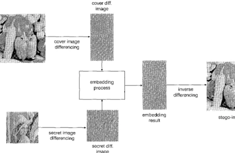
cover diff. image inverse differencing
t
I $ i ”- - -
Secret inage dfferenc ng ’ secret diff. imageFig. 3 Proposed image hiding method
Hiding data in images by replacing their LSBs is a simple embedding method that utilises the insensitivity of the human visual system to small changes in the image. The visual system’s sensitivity indeed varies from smooth areas to contrastive areas. The amount of pixel-value modification which causes a just noticeable change in a smooth image area is smaller than that in an edge or contrastive area. Edge or contrastive areas can suffer greater changes with imperception. In the hiding process we propose, we use this characteristic to hide more data in contrastive areas and less in smooth areas. This helps to hide more data imperceptibly in an image.
The proposed hiding method is sketched in Fig. 3, which consists of three major parts: the process of cover image differencing, that of secret image differencing, and the embedding process, which are described subsequently. 2. I
Cover and secret images used in the proposed method are assumed to have 256 grey values. To get a difference image from a given cover image, we obtain the grey value g of a pixel in the resulting image from every non-overlapping two-pixel subimage (p’, p ” ) of the cover image, in a zigzag
order as shown in Fig. 4, by
Cover and secret image differencing
g = g” - g’
+
128 (1)where g‘ and g” are the grey values of p’ and p ” , respec- tively. The resulting data stream is just a half of the cover image in size.
The process of obtaining the difference image from the secret image is the same as that for the cover image except that we calculate the difference value of the grey values of every two adjacent pixels, instead of every non-overlap- ping two-pixel subimage, in zigzag order. So the size of the resulting stream is the same as that of the secret image. In the calculation of the difference value of the top-leftmost pixel of the secret image, we assume that its previous
pixel’s grey value is 128. For convenience, in the sequel we call the difference image from the secret image as the secret difference image, and that from the cover image as the cover difference image.
In addition, we quantise the resulting difference values into n ranges as illustrated in Fig. 5. These ranges are
IEE Proc.-K. lmuge Signul P r o c e x , Vol. 147, No. I , Fehrirciry 2000
embedding
result stego-image
indexed by 1 though n, respectively. A difference value which falls in a range with index k is said to have index 1;.
The range intervals are selected in this study to meet the following criteria: all the values in a certain range (i.e. with an identical index) are considered as close enough, and if a value in the range is replaced by another in the same range, the change cannot be easily perceived. The range intervals of difference values we choose are based on the visual system’s sensitivity variation from smooth to contrastive areas. The pixels in the contrastive area with difference values far from 128 may tolerate larger value changes than those in the smooth area with difference values near 128, when judged with the same sensitivity by human percep- tion. So we create smaller ranges near 128 and larger ones far from 128 for the purpose of better replacement with
Fig. 4
und secret images
Zig-zug order iised jbr calciilLrtiiig rl[ff&rence vnliies of both c o i w
0 128 255
Fig. 5
ivnges
Index 1 to n is assigned to each of the ranges
Qiiuntiscition of d@rence I U I L ~ 0 to 255 ii7to 17 ~riieqiicrl
less noticeable results. This strategy helps us to embed more information in contrast areas with less perception.
2.2 Image embedding process
The proposed image-embedding process consists of two steps: grey-value replacement, and the inverse differencing of the stego-image.
2.2.
I
Gre y-value replacement: An overview of thereplaccnient process is given in Fig. 6. For each pixel p 5 in
the secret difference image S, we find a pixel y, in thc cover difference image C whosc grey value has the same index as that of P . ~ , and hide 17, by replacing the value o f p ,
with that of p s . Although the grey-value distributions of S and C are similar, there may exist insufficient pixels in C which have the same index as that of a certain pixel in S which we want to embed. So it is necessary to adjust the values of some pixels in C into the new values which are insufficient for embedding before the whole replacement work begins. The adjustment work starts by counting the total number of pixels of every grey value from 0 to 255 in images S and C, respectively, and computing the total count for each index. The total counts of indices from 1 to 72 for both S and C are then checked to find out 'insufficient indices'. We say that an index k is insufficient if the total count of the index li in C is smaller than that in S. The range of grey values that is represented by an insufficient index k is called an insufficient range. Ranges which are not insufficient are called excessive. For every insufficient range wc need to accuinulate enough pixels in C that arc not with index k to complement the amount of insufficiency and adjust their indices to k by changing the values of the pixels to a value in the insufficient range. In this process, the adjustment work starts after the accuniu- lation works of all insufficient ranges are processed. In the accumulation process we record only the number of pixels
secret difference image S select pixel P, in S
--
with index k find pixel P, in C index k adjusted cover difference image C replace value of P, by that of P, andIt
record index index record pixel embedding exhausted ? resultof each grey value that is to be adjusted as well as the new grey value which the pixels will be adjusted to have. We accumulate for an insufficient range R a sufficient number
of pixels by collecting the grey values spreading out of both ends of R. In this procedure we collect grey values from all of the ranges except the processed insufficient ranges. The number of pixels with a given grey value g
Ivhich can be changed to have a new value in an insuffi- cient range R is determined by the quantity of the need in R and the number of pixels with g . The accumulation work for R is finished when a sufficient number of pixels is collected. There may exist more than one insufficient range which need be processed. The order of processing the insufficient ranges in our method is decided by how large the distance of an insufficient range is to a nearest excessive range. To avoid the abrupt changes of grey values in some pixels, we apply the accumulation work to the insufficient range with the largest distance first.
After all the insufficient ranges are checked and the numbers of pixels to be changed are accumulated, the work of adjustment is performed by randomly traversing C using a pseudorandom generator, which visits each pixel in C only once. For every visited pixel in C with a grey value that needs to be changed, we change it to a value of the insufficient range according to a record obtained in the previous accumulation work. Since the adjustment work may cause more perceptible changes in some pixels, the random working mechanism provides a way to scatter the distortion over the whole image. After the adjustment process, the adjusted cover difference image is ready for use in subscquent replacement work.
For the purpose of easily finding the desired p , in C which has the same index as py, we rearrange all the pixels in C into an n-list structure as illustrated in Fig. 7. Every list in the structure has an index which corresponds to the index of a grey-value range mentioned previously. Every node in the lists is a record of the location in C. A process of traversing every pixel of C is applied, in which we put the visited pixel into the rear of the corresponding list according to the index of its grey value. For example, if the location of 4866 in C with a value of 165 is visited and if the grey value belongs to the range whose index is k , then we add a node with the value 4866 to the rear of list k. Furthermore, we use a pseudorandom generator to permute the traversing order of the pixels in C instead of scanning through C sequentially. We use the permutation order to visit each pixel in C only once. This pseudorandom mechanism aims to achieve cryptography. This means that if an illicit user does not have the seed of thepseudo- random generator used in the image hiding process, the user cannot easily find out the correct traversing order. So,
process according location 4866
to permutation
order
/
cover difference
image range n
c17.
the steps of extracting the hidden image cannot be followed successfully.
After constructing the list structure we find for every pixel in S the Corresponding pixel in the list structure that has the same index to accomplish the replaccnient work. We process every pixel of S in the zigzag order mentioned previously. For each visited pixel p $ in S with index k, we extract the head element in the lcth list of the list structure which denotes a location in C, and replace the grey value of this location with the grey value of p r . For example (Fig. S), if we visit a pixel in S with grey value 168 and index k ,
then we extract the head element from list IC, whose value 4866 is a location in C where we want to do the replace- ment work. The grey value of the visited pixel is used to replace the grey value appearing in location 4866 of C, i.e. 165 is changed into 168. The replacement process is finished after all pixels in S are processed.
The grey value replacement process described is effi- cient because the one-to-one mapping between the pixels of the secret difference image and those of the cover difference image in the process can be built by traversing both the cover difference image and the secret difference image only once.
2.2.2 Inverse image differencing: In the inverse
image differencing process which produces a stego- image, for each difference values d' in the processed cover difference image, an inverse calculation for this value is performed to find the grey values g:) of the corresponding two-pixel subimage ( J I - ~ , p : ) of thc
stego-image whose difference value is d. Because we want to cause less perceptive distortion, the information about the grey values (gip I , gi) of the corresponding two-pixel subimage (pi ~ I , pi) in the original cover image is needed.
Assume the difference value of (gip g,) is d. We produce (&, ,
d)
according to the following equations:The two equations together satisfy the requirement that thc difference of
gip
I and g: is d'. Because the equations cause._ zig-zag through secret diff. image embed 168 into cover diff. image [7 list I
, A A
select head 1148661 list k element of kth list I0
list ncover diff. image
list structure of
cover diff. image
Fig. 8
IEE Pro<,.-Vir. linage Signal Pvocerr., RI/, 147. No. 1. l'ehruui]~ 2000
Propo.cer(pi-ocer.rfi- enibedding &ita into cover rl{fference rintigcj
changes in gip and g, nearly equally to produce g: ~ and
g;, the distortion caused by changing g i p , and g,, is
averaged over this two-pixel pair and so is less. Some of the calculations may cause g{. or g:-I to fall off the boundary of the range [O, 2551 of a pixel value. In such cases we set the pixel value to the boundary value, i.e. to 0 or 255, and readjust the othcr pixel value to a new value to preservc the difference value of gi ~ I and g: to be d'.
2.2.3 Embedding of leading information: Sincc an
extra table is constructed to record the index of the grey value of each pixel during the replacemcnt process, thc table must be available and used in the process of extract- ing the secret image from the stego-image. One can leave the table in a separate place or just hide it into the cover image. The latter way needs extra processing, in which we use the Muffmaii coding method to reduce the size of the table because the indices in our proposed niethod, with the values 1 to M , concentrate on just a few values. More
specifically, we embed into the cover image the following extra information: ( a ) the width and hcight of the secret image, ( b ) the number of quantised ranges, the boundaries
of each range, the number of elements in each quantised range, which are needed to construct the Huffman tree, and finally ( c ) the table of indices, which is organised as a bit stream generated by the Huffman coding method. This leading information provides a way to use different numbers of ranges and different range boundaries in the embcdding process. The entire leading information, taken as a bit stream, is embcdded into the LSBs of the cover image randomly. We walk through the covcr differcnce image using a pseudorandom number generator and embed every six bits of the bit stream into a pixel-pair of the original cover image, i.e. each pixel in this pixel-pair takes three bits as the rightmost bits. After embcdding the bit stream we use the rest of the cover difference image to hide the secret difference image, as described previously.
3 Process of extracting hidden image
The process of extracting the hidden image is proceeded by using first the seed of the pseudorandom number genera- tion to extract out the data that are embedded i n the stego- image. A stcgo-difference image S,, is produced from the stego-image S using a method similar to that for producing the cover diffcrence image in the hiding process, and the seed of pseudorandom number generation is used to produce the same traversing order for visiting Sc1 as in the embedding process.
Morc specifically, we extract the leading information embedded in the stego-image directly from the three LSBs of the grey values of each pixel-pair in
S
that corresponds to the visited pixel of Sc[, The grey values of the embedded secret difference iinage are extracted then by visiting the rest of the pixels of Si,. We rearrange S,, into an n-liststructure as in the embedding process. The same list used in the embedding process is reconstructed by the same traversing order. And then the list of the range indices and the n-list structure are used in extracting the grey values from S,, to build the secret difference image. In short, the secret image can be recovered by applying an inverse differencing process to the secret difference image.
4 Experimental results
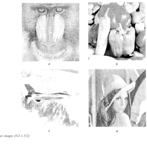
In our experiments four cover images arc used, as shown in Fig. 9, each with size 512 x 512, and the reduced-sized
1 -
a
C
Fig. 9 Cover moges (312 x 512)
n ‘Mandrill’
b ‘Peppers’
c ‘Jet’ il ‘Lena’
version of these images are used as the secret images, each with two sizes 256 x 512 and 256 x 256. The mean p and
the standard derivation o of the grey values of the pixels in each image are shown in Table 2. It is seen that the ,u values of the images are quite different but those of the difference images are all close to 128 and the value of each difference image is smaller than that of the original image. Since the histograms of the difference images are similar in shape and the o values are small, the effort to find similar pixel values in performing grey value replace- ment using the difference cover image and the difference
b
Y
d
secret image is less than that using the original cover image and the original secret image.
A simple LSB-replacing experiment was conducted for
the purpose of comparison. We embedded each secret image into the four cover images by directly replacing the four LSBs of the grey values of the pixels of the cover images, respectively. Also, four experiments were conducted to test the proposed method in which two sets of ranges were used for quantising the difference values g for the purpose of comparison. The ranges are illustrated in Table 3. The experiments so are divided into two groups by
Table 2: Means and standard derivations of grey values of cover images, cover difference images, secret images, and secret difference images
Cover image (51 2 x 51 2)
Mandrill Jet Lena Peppers Mandrill Jet Lena Peppers
Cover difference image (256 x 51 2)
Mean 11 135.45 179.28 130.32 127.15 128.03 128.00 127.99 128.00
Std p 38.99 46.68 44.10 52.84 20.13 12.43 10.46 11.62
~ ~
Secret image (256 x 51 2)
Mandrill Jet Lena Peppers Mandrill Jet Lena Peppers
Secret difference image (256 x 512)
Mean 11 135.43 179.46 130.37 127.18 127.99 127.98 128.00 128.00
Std p 38.97 46.59 44.10 52.64 28.66 18.57 16.89 15.01
Secret image (256 x 256)
Mandrill Jet Lena Peppers Mandrill Jet Lena Peppers
Secret difference image (256 x 256)
~
Mean 11 135.48 179.34 130.36 127.43 128.00 128.02 127.98 128.00
Std p 35.57 46.21 44.1 1 52.76 18.77 16.91 16.89 15.85
Table 3: Two sets of quantisations of difference values and corresponding ranges and sizes used in experiments (top: range table 1 ; bottom: range table 2)
Range C 7 1 72-103 104-119 120-127 128-135 1 3 6 1 5 1 152-183 184-255
Size 72 32 16 8 8 16 32 72
Index 1 2 3 4 5 6 7 8 9 10 11
Range &45 4 6 7 7 78-99 10Cb113 114-123 124-131 132-141 142-155 1 5 6 1 7 7 178-209 21&255
Size 46 32 22 14 10 8 10 14 22 32 46
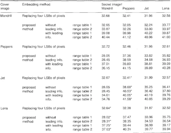
using different range tables. We embedded each 256 x 5 12 secret image into the cover images without the leading information, and then embedded each 256 x 256 secret image into the cover images with the leading information. The peaks of the signal-to-noise (PSNR) values of the five experiments are shown in Table 4. The resulting stego- images of the methods that use ‘Jet’ as the cover image and ‘Peppers’ as the secret image are selected and shown in Fig. 10, and those that use ‘Lena’ as the cover image and ‘Mandrill’ as the secret image are shown in Fig. 11. It is seen that changes of the LSBs may cause noticeable changes in smooth areas like the background of ‘Jet’ (Fig. 1Ou) and the shoulder of ‘Lena’ (Fig. l l a ) . The PSNR values of the results of our proposed method are almost all higher than that of the LSB-replacing method except in some of the results from using ‘Mandrill’ as the cover image or the secret image. This is becausc that the value U of the difference image of ‘Mandrill’ is larger than
those of the other images, and so more quantity of grey value changes are needed during the embedding steps. The selected stego-images in Figs. 10 and 1 1 show that the results of thc proposed method have less noticeable changes than those of the LSB replacing method, even when the PSNR is poor. Generally, the PSNR values coming from using the second range table are higher than those of using the first range table owing to the smaller range sizcs of the second range table. The amounts of data resulting from embedding a 256 x 256 image plus its leading information is smaller than that resulting from embedding a 256 x 512 image without the leading infor- mation. The PNSR values of the latter are smaller than those of the former.
It is found that the embedding results of the proposed method are similar to the cover images. The quality is good even in a stego-image with a poor PSNR. This demonstrates that the changes made in edge areas are not noticeable.
Table 4: PNSR values of embedding secret images into cover images
Cover image
Embedding method Secret imaget
Mandrill Peppers Jet Lena
Mandrill
Peppers
Jet
Lena
Replacing four LSBs of pixels proposed without method leading info.
with leading info. Replacing four LSBs of pixels proposed without method leading info.
with leading info. Replacing four LSBs of pixels proposed without method leading info.
with leading info. Replacing four LSBs of pixels proposed without method leading info.
with leading info. range table 1 range table 2 range table 1 range table 2 range table 1 range table 2 range table 1 range table 2 range table 1 range table 2 range table 1 range table 2 range table 1 range table 2 range table 1 range table 2 32.68 32.65 33.87 39.08 40.44 32.72 28.05 28.45 37.01 36.15 32.67 28.05 28.45 34.61 34.76 32.64* 28.02’ 28.31 * 37.25* 37.03* 32.41 32.05 32.26 39.98 41.12 32.46 37.36 38.59 39.80 41.15 32.41 * 38.69* 40.53* 40.05* 41.58‘ 32.38 37.47 38.35 39.44 40.31 31.96 32.24 33.00 40.22 40.96 31.96 33.82 34.68 38.81 39.89 31.99 35.25 36.42 40.1 9 40.85 31.87 33.96 34.53 38.99 39.77 32.58 33.77 33.97 39.87 41 .OO 32.61 35.82 36.93 39.09 40.28 32.57 36.41 37.80 39.76 39.29 32.52 35.75 36.54 39.17 39.94 ~
-;. Secret images are of size 256 x 512 except those used in proposed method of embedding with leading information (with size 256 x 256).
* Resulting stego-images are shown in Figs. 10 and 1 1 .
a
C
b
d
e
U Result by replacing four LSRs OC pixels
b Result of proposed mzthod without embeddmg leatiiiig inforination and llsing first range rahle
c Result of proposed method without embedding leading infot-malion and using second range table
0 Result of proposed incthod embedding lead~ng ~ n ~ o i ~ t i i a t i o n and Using first range table
e Result of propmed inethod embedding leading information and using second range table
5 Conclusion value replacement. The method utilises the characteristic of the human visual system's sensitivity to embed more secret We have proposed a novel method for embedding a grey- data. The method not only provides a way for embedding valued secret image into a cover image and preserving the large quantities of data imperceptibly into cover images, secret image with no loss. The method produces the stego- but also offers an easy way to accomplish cryptography. In image without noticeable changes. Image differencing the future, we will study the problems of embedding operations are eniployed to create difference images from images without extra tables and embedding images into which similar values can be found easily in doing grey colour images.
d c b d e Fig. 11
U Result by replacing iiiur I SDs of pixel\
h Result o f proposed method without etnheddiny leadiiig infot in:itmi and uhing first lunge tiiblc
c Result of proposed method without emhcddiiig leading i n f i b i malioii and uring second r:ingc tablc
d Result of pi-oposed method embedding Iatdiiig inhiination and using first range table
R<.YZdli/lg ff7ZUge\ O / evpci.inrcmrr O/
llesult of‘ proposed method etnhcddiiig leading i i i t i ~ i timion and usitig second range t h l c
6 Acknowledgment
This work is supported partially by National Science Council, R. 0. C. under grant NSC86-2213-E009-113.
7 References
I BRASSIL, J.T., LOW, S., MAXLMCHUK, K.F.. and O’GORMAN. 1 . : ‘ F h t r o n i c markinlr and identification techniuue to discouralre document copying’, IEEE J ‘id h e t / \ C o r i i n i i i n i , 19’35, 13 (X), pp i 4 0 5 1503
BENDER, W , GRUIIL, D , MOIIIMO IO, N
.
and LU, A ‘ Icdiniquc52
for data hiding’, ZBM $yrt. 1; 1996, 35. (3,4), pp. 313 330
3 I U R N E R , L.F.: ‘Digital data security system, 1980. Patent IPN Mi0 89’ 08915
4 WALTON, S.: ‘Image authentication fbI il >Iippci y new age’. Ihh h h l
J., 1995, 20; (4), pp. 1 8 ~ 2 6
5 BENDER, W., M O K I M O I 0 , N., anti (iRL1II , U.: ‘Method and
appardtus for data hiding in images, 1997, US parent 5689587
6 KOCH, E., and ZHAO, J.: ‘Towards robust and hldden image copyt-ight labeling’. Proceedings of 1EEE workshop o i i .Vunlinc,ur .sf,quul u i / d
imuge pmcec’sing, 1995, Thessaloniki, (>recce, pp. 452-455
7 8 9 I O I I 12 13 14
COX. I.J.. KILIAN, J., LLIGHTON, 1:.1., and SHAMOON, T.: ‘Secure q x x t r t i i n \vateriitarking for iiiultiinedia’,
, 1997. 6 , (12). pp. 1 6 7 3 ~ ~ 1 6 8 7
Hi. J.. and M M S U I , K.: ‘Enibcddiiig a seal into a picture U
orthogonal L\ avelet transform’. Proceedings of Multiiiiedia’96. ( I f’rcss, Piscatawiy, NJ, 190s). pp. 5 14 52 1
iid MANJUNATH, U . S . : ‘A robust embedded data fi-om clclits’. P/.OC. SPIE-I/lf. Soc. q 1 t . E/ig , 1998. 3312, pp.
HSU. C.I . , and WU, J.L : ’DC‘I-Bascd \vaterrnarking for video’. I
BARNI, bl.. E3ARTOL,INI, F., C‘APPI:LLINI. V , and PIVA, A . : ‘A DCT-
dotnain \yhtcm for rohust image \.vateniiarking’, Sig/iuI Pmces,.. 1998.
66% pp. 3 5 1 372
I)I-’I’I’%MANN. H.: ‘Information hiding terminology. Proceedings of first
inr’l uorkshop 011 ‘Information hiding’ Lcclure Notch in Comptitrr ‘ Science’ no. I 174 (Spt-ingcr-\’ei-la:!, Berlin, 1996), pp. 347 349 LIA\V, M.S.. and C‘HF.N, L.H.: ‘An effective data hiding method’.
Procccdings of IPPR colifet-ciicc on ‘Computci- vision, graphics, and image processing’. 1997. Tdiwan, R.O.C.. lip. 146-1 53
CiONZALEZ. K C . , and MOODS. R.E.: ‘Digital iiiiage procesaing’ (z4dd~son Wesley. NCM York. 1992)
7 i Z r / l . S . C ’ U / 7 \ i / / / I . Elecri.o/, , 1998, 44. pp. 206-216
The IEE Online Journal service
is
available direct from the IEE over
the
Worldwide Web.
This service includes the IEE's rapid-publication letters journal,
Electronics Letters, and all 12 titles of /€E Proceedings. Articles are
stored in PDF format and may be viewed and printed using the Adobe@
Acrobat@
Reader.
http:/lioj.iee.org.uk/
Cross-journal searching of bibliographic records (inc. authors, titles, abstracts)
Browsable table of contents pages for each journal issue
0
Typeset quality display of articles from mid-I996
Backfile from 1994 t o mid-1996 based on scanned images
Ability t o print articles locally
0