STUDY OF DUV 248 LENS A/B AND LASER
CHAMBER LIFETIME EXTEND BY
STUDY OF DUV 248 LENS A/B AND LASER
CHAMBER LIFETIME EXTEND BY EFFICIENT
POWER CURVE CONTROL
A Thesis
Submitted to Degree Program of Photonic Technology College of Photonics
National Chiao Tung University in partial Fulfillment of the Requirements
for the Degree of Master
in
Photonic Technology
1
3
STUDY OF DUV 248 LENS A/B AND LASER
CHAMBER LIFETIME EXTEND BY EFFICIENT
POWER CURVE CONTROL
Student: S.C.Shih Advisor: Dr. Y.L.Wang
Degree Program of Photonic Technology National Chiao-Tung University
Abstract
Along with the continuous advancement of integrated to the nanometer
level, use the laser source for exposure is more and more popular to instead
of the traditional bulb. We can get the benefit of the integrated line width
improve to nanometer level, but the cost and maintenance of the laser
machine becomes increasing complex. The frequency of repair and
maintenance to increase, it also decreases the efficiency of the manpower.
The paper is study the ASML DUV 248 scanner suffered lens A/B
seriously destroy event. And this event was getting worse and worse. It
caused the wafer level intensity trended down seriously. As we known, the
wafer level intensity affects the throughput of production. Before, we could
adjust VA angle or replace lens A/B to solve it. But lens A/B contamination
happened and happened again. It spent a lot of time, manpower and cost in
recovery. So how to reduce lens replaced rate or engineer’s loading was
necessary. According to experience, we found it cause from the lens A/B
was damaged by laser. In the last analysis, the root cause was higher energy
laser induce lens A/B contamination. We created original intensity control
method to extend lens A/B lens lifetime; moreover, it could extend Laser
chamber lifetime, either. This situation has been changed and proved it is
workable after the program was implementing.
TABLE OF CONTENTS
Chinese Abstract ... 1
English Abstract ... 3
Acknowledgement ... 5
Table of Contents ... 6
Table of Captions ... 7
Figure Contents ... 8
Chapter 1 Background Introduction ... 9
1.1 Investigation Motivation and Purpose ... 9
1.2 Investigation Background ... 9
1.3 Method and Instrument Description ... 11
Chapter 2 Experiment ... 15
2.1 Standpipe Diagram ... 15
2.2 Scanner Intensity Diagram. ... 16
2.3 Laser Energy Control Loop ... 18
Chapter 3 Result/Discussion(Experiment, Result, Analysis…) ... 21
3.1 Lens A/B Have Double Lifetime ... 21
3.2 Laser Chamber Have Double Lifetime ... 22
3.3 Methodology Change Compare with Production Yield ... 22
Chapter 4 Conclusion With the Model of Car Speed ... 24
Chapter 5 Conclusion (Root Cause, Improvement, Prevention) ... 26
Vita ... 27
7
TABLE CAPTIONS
Table 2.1 Lens A/B Replaced Statistics ... 15
Table 2.2 Laser Power w.r.t VA angle of the transmission rate ... 17
FIGURE CAPTIONS
Figure 1.1 Scanner Intensity Loop ... 9
Figure 1.2 A and B tools Wafer Level Intensity Trend Chart ... 11
Figure 1.3 Lens A/B Contamination Statuses ... 12
Figure 1.4 Lens A/B Lifetime & Laser Pulsed Energy Related Chart ... 12
Figure 1.5 Contamination of Lens A/B Cause by the (NH
4)
2SO
4... 13
Figure 2.1 Standpipe system flow ... 15
Figure 2.2 Standpipe System Flow with Scanner Intensity Control ... 16
Figure 2.3 Scanner Intensity Control Loop ... 17
Figure 2.4 New Scanner Intensity Control Loop ... 18
Figure 2.5 Laser Energy Control Loop ... 19
Figure 2.6 Intensity Curve ... 19
Figure 2.7 Laser E95 Comparable Data ... 20
Figure 2.8 Laser Performance Check... 20
Figure 3.1 A and B tools Wafer Level Intensity Trend Chart ... 21
Figure 3.2 A tool Lifetime Extend Estimate by Laser Working Voltage
... 22
Figure 3.3 Production Yield Compare ... 23
Figure 4.1 Old Concept of the Car Speed Control ... 24
Figure 4.2 New Concept of the Car Speed Control ... 25
9
Chapter 1 Background Introduction
1.1
Along with the continuous advancement of integrated to the nanometer level, use the laser source for exposure is more and more popular to instead of the traditional bulb. We can get the benefit of the integrated line width improve to nanometer level, but the cost and maintenance of the laser machine becomes increasing complex. The frequency of repair and maintenance to increase, it also decreases the efficiency of the manpower. It also is a large loading in our cost and manpower control, and it is major topic for study the root cause and improved the availability due to the exposure tools is the highest cost of semiconductor factory.
1.2 Investigation Background
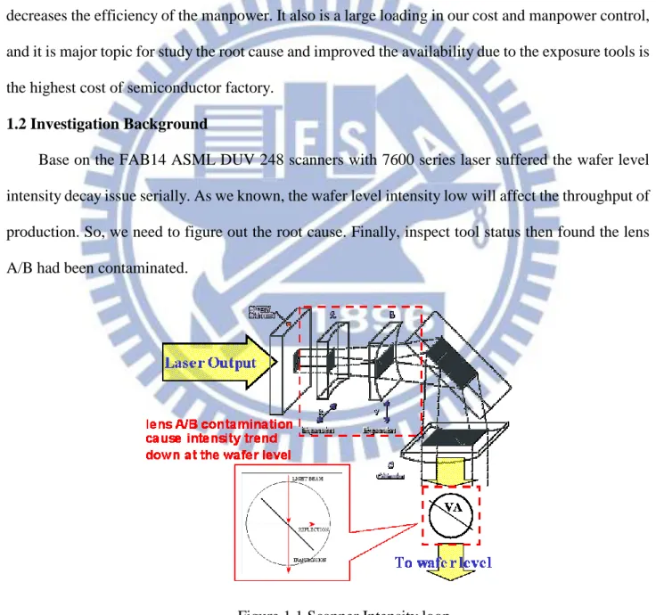
Base on the FAB14 ASML DUV 248 scanners with 7600 series laser suffered the wafer level intensity decay issue serially. As we known, the wafer level intensity low will affect the throughput of production. So, we need to figure out the root cause. Finally, inspect tool status then found the lens A/B had been contaminated.
Base on standard procedure, we could adjust wafer level intensity by:
Method 1 Adjust VA angle-The variable attenuator (VA) is used to control light transmission rate to the wafer level. When light hits the quartz plate of the VA, a part of light will pass through and the other will be reflected to the beam dump (absorbed). So, we adjust VA angle to obtain the required intensity (as a light regulator).
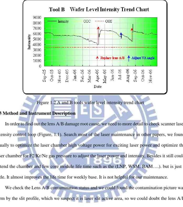
Method 2 Replace Lens A/B-After a mount of shots, the lens A/B will be contaminated. If the lens A/B status of contamination was too worse to recover by VA adjustment, the lens A/B will be replaced. But situation was out of the control; whether we adjusted VA angle or replaced lens A/B still could not fix it. As shown below, we can’t keep intensity stable anymore (figure 1.2). Lens A/B contamination happened and happened again.
11
Figure 1.2 A and B tools wafer level intensity trend chart 1.3 Method and Instrument Description
In order to find out the lens A/B damage root cause, we need to more detail to check scanner laser intensity control loop (Figure, 1.1). Search most of the laser maintenance in other papers, we found usually to optimize the laser chamber high voltage power for exciting laser power and optimize the laser chamber for F2/Kr/Ne gas pressure to adjust the laser power and intensity, Besides it still could extend the chamber and few core module life time such as the (LNP, WSM, BAM….). but is just a little. It almost improves the life time for weekly base. It is not helpful for our maintenance.
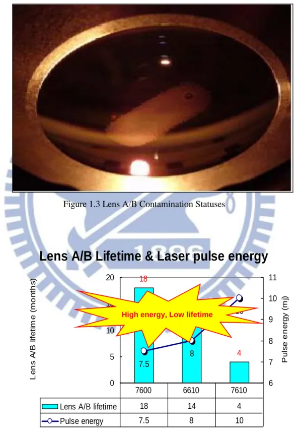
We check the Lens A/B contamination status and we could found the contamination picture was form by the slit profile, which we suspect it is laser slit active area, so we could doubt the lens A/B contamination was cause by the laser and we simulate the laser intensity and laser pulse energy VS the Lens A/B lifetime. We could found a related status is the Lens A/B lifetime VS Laser pulse energy come out the result is Lens A/B life time is low when the laser pulse energy is high, and Lens A/B lifetime is high when the laser pulse energy is low.
We could suspect the laser pulse energy is the key factor to influence the Lens A/B lifetime, and we could set up the experiment for the laser pulse energy with the Lens A/B lifetime related issue to figure out the root cause
Figure 1.3 Lens A/B Contamination Statuses
Lens A/B Lifetime & Laser pulse energy
18 14 4 7.5 8 10 0 5 10 15 20 L e n s A /B l if e ti m e ( m o n th s ) 6 7 8 9 10 11 P u ls e e n e rg y ( m j)Lens A/B lifetime 18 14 4 Pulse energy 7.5 8 10
7600 6610 7610
High energy, Low lifetime
13
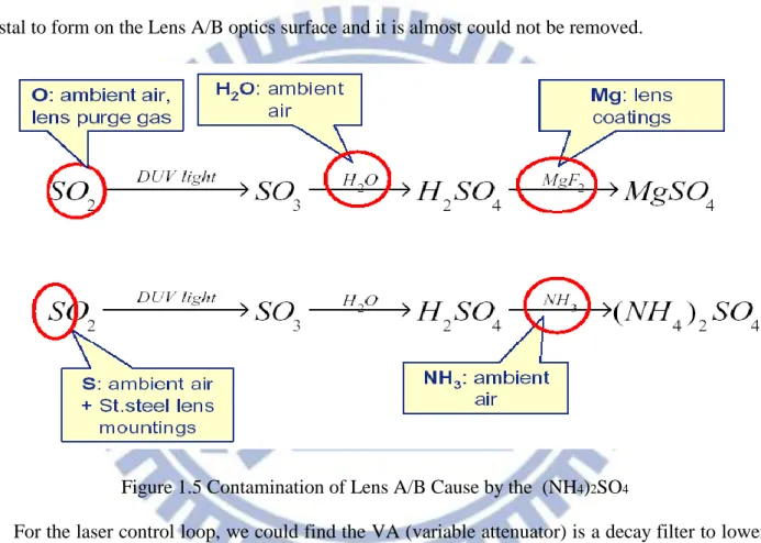
We still to check the contamination part for analysis and found that most of the part was form by the (NH4)2SO4. , then we check the chemical and analysis the root cause. We suspect the DUV light is the major factor to provide the energy to form the (NH4)2SO4. It is a major topic the study the pulse energy effect and the defect type.
Besides, we still try to remove the contamination by use many methods, even we use the removable chemical that suggest by zeiss and ASML, but it still difficult to remove it. So it is like crystal to form on the Lens A/B optics surface and it is almost could not be removed.
Figure 1.5 Contamination of Lens A/B Cause by the (NH4)2SO4
For the laser control loop, we could find the VA (variable attenuator) is a decay filter to lower down the laser intensity to fit scanner need, and it almost set around 70% lower down the laser output to fit the scanner need. And we found the lens A/B damage is major comes from the laser output is too high and it damage the lens A/B and induce the optics contamination. The contaminations also decay the intensity of the laser, and need to frequency to swap it to gain the requirement. So we need to maintain it again and again to reduce the productivity for litho scanner and waste the manpower.
If we could dynamic to control the laser output intensity and just to control the scanner requirement to fit the exposure wafer need then we can lower down 30% output to reduce the damage
of the lens A/B. We study the laser control parameter and found one of thousands of parameters is to control laser output percentage, it calls parameter C24. We think we can adjust the C24 parameter to fid the wafer level intensity and let the VA keep 100% output to minimize the damage of the lens A/B which laser output optics for beam expender of x, y control.
We can set up the experiment for parameter C24 adjustment to fit the wafer level intensity requirement and dynamic to control the C24 parameter to monitor the intensity variation and the lens A/B life time trend chart for the data collection and analysis to fit our suspect model.
15
Chapter 2 Experiment
According to the lens A/B replaced record; we had replaced 14 set of lens A/B for recovery within one year (table 2.1). It spent a lot of time, manpower and cost in recovery.
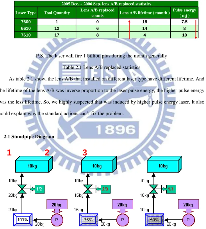
P.S. The laser will fire 1 billion plus during the month generally Table 2.1 Lens A/B replaced statistics
As table 2.1 show, the lens A/B that installed on different laser type have different lifetime. And the lifetime of the lens A/B was inverse proportion to the laser pulse energy, the higher pulse energy was the less lifetime. So, we highly suspected that was induced by higher pulse energy laser. It also could explain why the standard actions can’t fix the problem.
2.1 Standpipe Diagram
Figure 2.1 Standpipe system flow
Laser Type Tool Quantity Lens A/B replaced
counts Lens A/B lifetime ( month )
Pulse energy ( mj )
7600 1 0 18 7.5
6610 12 6 14 8
7610 17 8 4 10
2005 Dec. ~ 2006 Sep. lens A/B replaced statistics
In figure 2.1 you can see the processing flow of the standpipe-filled. Blue box is a standpipe that has a kilogram capacity of 10. Violet object is a pump for supplying 20 kilograms water to the standpipe. The water of the pump source passes through the pipe (while object) that with one hundred percent of the transmission rate, the water will flow over of the standpipe. So, we used regulator with 1/2-proportioned (green object) to control 10 kilograms water could transfer to the standpipe only. One day, the pipe was blocked to have seventy-five percent of the transmission rate only (figure 2.2). The regulator must be adjusted to 2/3-proportioned to ensure enough capacity of the standpipe. As the same reason, the regulator must be adjusted to 1/1-proportioned to cover the pipe with fifty percent of the transmission rate (figure 2.3).
In the program, we could found a doubtful point: If the standpipe needs to be filled by 10 kilograms water only, why should we need to support 20 kilograms? And install the regulator especially for filter out unnecessary water?
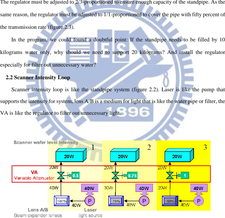
2.2 Scanner Intensity Loop
Scanner intensity loop is like the standpipe system (figure 2.2). Laser is like the pump that supports the intensity for system, lens A/B is a medium for light that is like the water pipe or filter, the VA is like the regulator to filter out unnecessary light.
17
VA was the adjustable device in the original ASML scanner intensity control system. It blocked and filtered out unnecessary light (figure 2.3). So, the higher laser energy induced the lens A/B contamination and replacement needed the VA adjustment happening with increasing frequency.
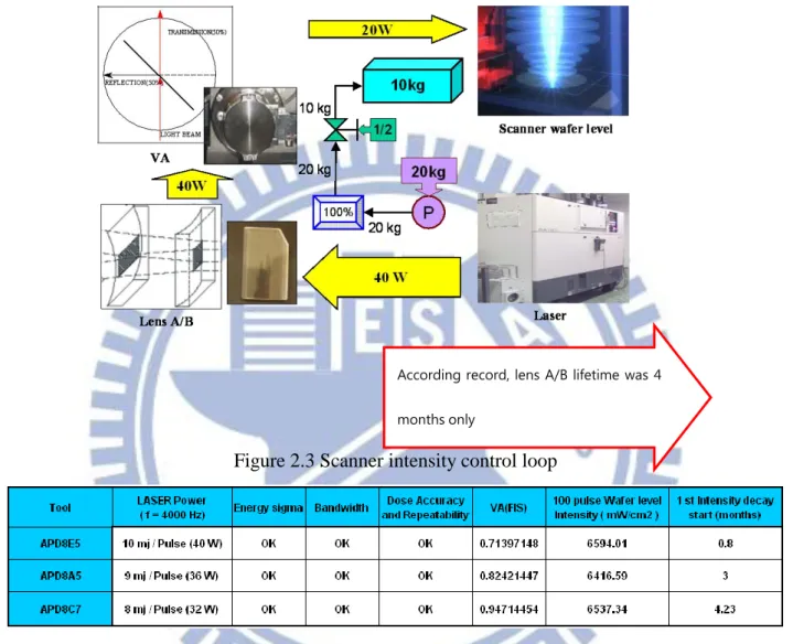
Figure 2.3 Scanner intensity control loop
Table 2.2 Laser power W.R.T VA angle or the transmission rate
According to the understanding of the ASML scanner intensity control system, we have a new idea as below.
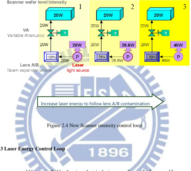
1. To fix the transmission rate of the VA to the maximum as possible. (figure 2.4 transmission rate of the green object was 1/1-proportioned)
2. Adjust laser energy to match the required of the wafer level intensity, 3. Increase laser energy if the lens A/B had contamination
According record, lens A/B lifetime was 4
In other word, we would use Laser power adjustment to instead of ASML standard VA angle adjustment method.
Figure 2.4 New Scanner intensity control loop
2.3 Laser Energy Control Loop
Laser energy could be controlled by the piezoelectric devices or software. In the case of Laser energy adjustment, we are willing to use software. It had no difficulty in operation and spent less time.
19
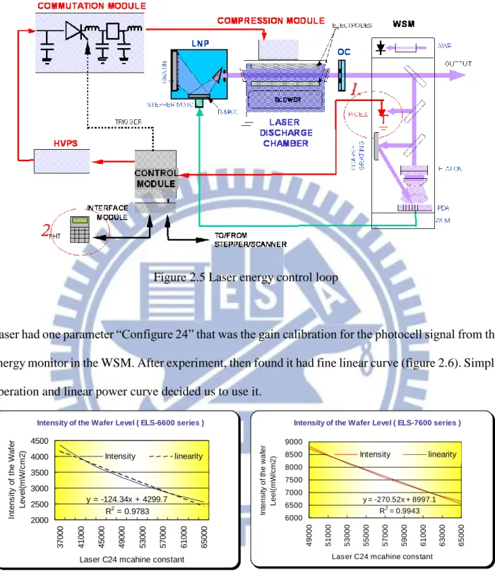
Figure 2.5 Laser energy control loop
Laser had one parameter “Configure 24” that was the gain calibration for the photocell signal from the energy monitor in the WSM. After experiment, then found it had fine linear curve (figure 2.6). Simply operation and linear power curve decided us to use it.
Intensity of the Wafer Level ( ELS-6600 series )
y = -124.34x + 4299.7 R2 = 0.9783 2000 2500 3000 3500 4000 4500 37000 41000 45000 49000 53000 57000 61000 65000
Laser C24 mcahine constant
In te n s it y o f th e W a fe r L e v e l( m W /c m 2 ) Intensity linearity
Intensity of the Wafer Level ( ELS-7600 series )
y = -270.52x + 8997.1 R2 = 0.9943 6000 6500 7000 7500 8000 8500 9000 49000 51000 53000 55000 57000 59000 61000 63000 65000
Laser C24 mcahine constant
In te n si ty o f th e w a fe r L e e l(m W /cm 2 ) Intensity linearity
Figure 2.6 Intensity curve
From performance index, the new method could lower LASER working voltage but other performance index like E95 of laser pulse bandwidth was kept with original data (figure 2.7) which is major concern by the CD variation of the proximity effect. Secondly the laser pulse energy was kept
the same and stable (figure 2.8). The laser pulse energy is still concern by the CD variation which was impacted the CD mean value effect. The result is which we had anticipated. Lower LASER working voltage will extend LASER chamber, WSM and LNP lifetime.
Figure 2.7 Laser E95 Comparable Data
21
Chapter 3 Result/Discussion
(Experiment, Result, Analysis…)
3.1 Lens A/B have double lifetime.
We used old type Lens A/B and new methodology at APD8E3 from Nov. 2006, then it got great improvement, kept wafer level intensity stable more than 8 months and low intensity decay rate (<15 mW/cm2 / month) till now. Besides, we tried to assess the effects of the long-life Lens A/B that was new design from ASML at APD8E5. The performance shows new method with old lens A/B is better than old methodology with long life lens A/B, kept stable 5 months and have monthly 334 mW/cm2 intensity decay rate. (Old type: 66,000 NT/set; New type: 102,400 NT/set)
Figure 3.1 Tool A and Tool B wafer level intensity trend chart
Tool A New Methodology Old Methodology Tool B Tool A New Methodology Old Methodology
APD8E5 Wafer Level Intensity Trend Chart
0 1000 2000 3000 4000 5000 6000 7000 8000 9000 S ep-05 O ct -05 N ov-05 D ec -05 Ja n-06 F eb-06 M ar -06 A pr -06 M ay-06 Jun-06 Jul -06 A ug-06 S ep-06 O ct -06 N ov-06 D ec -06 Ja n-07 F eb-07 M ar -07 A pr -07 M ay-07 Jun-07 Jul -07 Date In te n si ty
Intensity OOC OOS
Long life Lens A/B with old Methodology
According to long lifetime Lens A/B’s profitability was better than old type. We will be glad to combine long lifetime Lens A/B with new intensity control methodology in the future. It’s effects was assessing. Currently, our Lens A/B lifetime had extended form 4 months to more than 8 months and it will help us to reduce 1,683,000 NT/year [17 X (12/4 – 12/8) X 66,000 NT/set].
3.2 Laser Chamber have double lifetime.
Lower LASER working voltage will extend chamber lifetime from 19 billion (≒ 16 months) to 39 billion(≒ 32 months), and it will help us to reduce 20,429,516 NT/year [17 X (12/16 – 12/32) X 3,204,630 NT/year]. 7610 Laser Performance 1000 1050 1100 1150 1200 1250 1300 1350 1400 1 3 5 7 9 11 13 15 17 19 21 23 25 27 29 31 33 35 37 Shots (billion) V ol ta ge ( v ) APD8E3 APD8E4 replace chambe r new method current statement estimated lifetime
Figure 3.2 APD8E3 Lifetime extend estimate by LASER working voltage
3.3 Methodology change compare with production yield. -No yield impact
23 TMR309 CP Yield 75 80 85 90 95 100 W 6 4 0 W 6 4 1 W 6 4 2 W 6 4 3 W 6 4 4 W 6 4 5 W 6 4 6 W 6 4 7 W 6 4 8 W 6 4 9 W 6 5 0 W 6 5 1 W 6 5 2 W 6 5 3 W 7 0 1 W 7 0 2 W 7 0 3 W 7 0 4 W 7 0 5 W 7 0 6 W 7 0 7 W 7 0 8 W 7 0 9 Date P e rce n ta g e ( % )
Totall Tool APD8E3
Chapter 4 Conclusion With the Model of Car Speed
We could easy to fit the research of the simple model for car speed control. In general, ASML request laser vender to provide the fully laser pulse energy to fulfill the scanner need to achieve the maximum WPH, but scanner side need to control the maxmum intensity to prevent the post optics damaged by the high intensity, so it design the VA (variable attenuator) to lower down the intensity to specific value. But it waste the intensity due to VA is a attenuator to decreased the intensity and waste around 30% intensity when all optics is new.
It like the car speed control. We fully use the engine to fulfill value to gain the maximum speed but due to we need to control the maximum speed to achieve the speed control is within the rule. So we add the brake to lower down the speed, but we waste the brake effect and the engine efficiency (figure 4.1)
2
100 km/hr
Lens A/B + VA Intensity
Engine Speed LASER
Laser
VA
scanner 6000
mW/cm
2 Brakes25
In the new model of the car speed control, we could control the engine by control the engine driving value to control the car speed and do not need to add the brake to lower down the speed. This is dynamic control the car speed by efficiency control to achieve accuracy value, which is a new concept to control car speed. It is like the new methodology to control the laser pulse energy to make it more efficiency and could lower down to the require value to achieve exposure energy and it could improve the Lens A/B life time and Laser chamber lifetime. (Fig 4.2)
Figure 4.2 New Concept of the Car Speed Control
2
100 km/hr
Lens A/B + VA Intensity
Engine Speed LASER scanner 6000 mW/cm2 VA Laser Brakes
Chapter 5 Conclusion
(Root Cause, Improvement, Prevention
According to experiment’s result, we make sure the root cause of the wafer level intensity decay issue is due to higher energy laser. And we find the new intensity control method is effective in extending lens A/B & laser chamber lifetime. The new intensity control method flow as below:
Figure 5.1 The New Intensity Control Method Flow
This methodology could save a lot of cost and also pass ECIP change management for cross FAB experiment sharing.
27
Vita
Study of DUV 248 Lens A/B and Laser Chamber Lifetime Extend by Efficient
Power Cure Control
Reference
[1] Trokel SL, Srinivasan R, Braren B: Excimer laser surgery of the cornea . Am J Ophthalmol 1983;;96:710-715 ASML service manual
[2] Grundfest WS, Litvack IF, Morgenstern L, et al: Effect of laser irradiation on human atherosclerotic aorta: Amelioration of laser-induced thermal damage. Paper FL-2, technical digest, Conference on Laser and Electro-optics, Anaheim, Calif, June 19-22, 1984
[3] Marshall J, Trokel SL, Rothery S, et al: An ultrastructural study of corneal incisions induced by an excimer laser at 193 nm . Ophthalmology 1985;;92:749-758
[4] Puliafito CA, Steinert RF, Deutsch TF, et al: Excimer laser ablation of the cornea and lens . Ophthalmology 1985;;92:741-748
[5] Krueger RR, Trokel SL: Quantitation of corneal ablation by ultraviolet laser light . Arch Ophthalmol 1985;;103:1741-1742
[6] Peyman GA, Kuszak JR, Weckstrom K, et al: Effects of XeCl excimer laser on the eyelid and anterior segment structures . Arch Ophthalmol 1986;;104:118-122
[7] Pellin MJ, Williams GA, Young CE, et al: Endoexcimer laser intraocular ablative photodecomposition . Am J Ophthalmol 1985;;99:483-484
[8] Lane RJ, Linsker R, Wynne JJ, et al: Ultraviolet-laser ablation of skin . Arch Dermatol 1985;;121:609-617
[9] Linsker R, Srinivasan R, Wynne JJ, et al: Far-ultraviolet laser ablation of atherosclerotic lesions . Lasers Surg Med 1984;;4:201-206
[10] Taylor RS, Singleton DL, Paraskevopoulos G, et al: Dependence of excimer laser ablation of human artery wall on wavelength and optical pulse duration. Technical digest, Conference on Laser and Electro-optics. San Francisco, June 9-13, 1986, pp 129a-129g
[11] Srinivasan R, Mayne-Banton V: Self-developing photoetching of poly(ethylene terephthalate) films by far-ultraviolet excimer laser radiation . Appl Phys Lett 1983;;41:576-578
[12] Srinivasan R, Braren B: Ablative photodecomposition of polymer films by pulsed farultraviolet (193 nm) laser radiation: Dependence of etch depth on experimental conditions . J Polym Sci Polym Chem Ed 1984;;22:2601-2609
[13] Sun M, Zigman S: Isolation and identification of tryptophan photo-products from aqueous solutions of tryptophan exposed to near-UV light . Photochem Photobiol 1978;;29:893-897
[14] Borkman RF, Hibbard LB, Kirk NJ: Lens damage from 337.1-nm laser radiation . Lens Res 1985;;2:109-120
[15] Lerman S, Borkman R: Spectroscopic evaluation and classification of the normal, aging, and cataractous lens . Ophthalmic Res 1976;;8:335-353
[16] Marshall J, Sliney DH: Endoexcimer laser intraocular ablative photodecomposition . Am J Ophthalmol 1986;;101:130
29
lesion . Br J Ophthalmol 1978;;62:134-144
[18] Parel J-M, Gelender H, Trefers WF, et al: Phaco-Ersatz: Cataract surgery designed to preserve accommodation . Graefes Arch Clin Exp Ophthalmol 1986;;224:158-162
[19] Keates R, Genstler D, Tarabichi S: Ultraviolet light transmission of the lens capsule . Ophthalmic Surg 1982;;13:374-376
[20] Van Heyningen R: Fluorescent derivatives of 3-hydroxydynurenine in the lens of man, baboons, and the grey squirrel . Biochem J 1971;;123:30-31
[21] Cooper G, Robson J: The yellow colour of the lens of man and other primates . J Physiol 1969;;203:411-417
[22] Zigman S: Photobiology of the lens , in Maisel H (ed): The Ocular Lens . New York, Marcel Dekker Inc, 1985;, p 305
[23] Dillon J: Photochemical mechanisms in the lens , in Maisel H (ed): The Ocular Lens . New York, Marcel Dekker Inc, 1985;, p 350