國
立
交
通
大
學
資訊科學與工程研究所
碩
士
論
文
利用資訊隱藏技術對 H.264 影片做真偽驗
證及內容保護之研究
A Study on Authentication and Protection of H.264 Video
Contents by Information Hiding Techniques
研 究 生:洪菽鴻
指導教授:蔡文祥 教授
利用資訊隱藏技術對 H.264 影片做真偽驗證及內容保護之研究
A Study on Authentication and Protection of H.264 Video
Contents by Information Hiding Techniques
研 究 生:洪菽鴻 Student:Shu-Hung Hung
指導教授:蔡文祥 Advisor:Wen-Hsiang Tsai
國 立 交 通 大 學
資 訊 科 學 與 工 程 研 究 所
碩 士 論 文
A ThesisSubmitted to Institute of Computer Science and Engineering College of Computer Science
National Chiao Tung University in partial Fulfillment of the Requirements
for the Degree of Master
in
Computer Science
June 2009
Hsinchu, Taiwan, Republic of China
利用資訊隱藏技術對
利用資訊隱藏技術對
利用資訊隱藏技術對
利用資訊隱藏技術對
H.264
影片做真偽驗證及內容
影片做真偽驗證及內容
影片做真偽驗證及內容
影片做真偽驗證及內容
保護之研究
保護之研究
保護之研究
保護之研究
研究生:洪菽鴻
指導教授:蔡文祥 博士
國立交通大學資訊科學與工程研究所
摘要
摘要
摘要
摘要
隨著視訊壓縮及視訊編碼技術的進步,數位影片逐漸在我們的生活中扮演重 要角色。本論文針對 H.264 影片,利用資訊隱藏技術,做影片快速檢索、驗證 及隱私權保護之研究與應用。在影片快速檢索部份,為了在視訊監控影片中快速 搜尋特定的可疑人物,我們提出了一個利用 H.264 編碼特性對影片做快速檢索 的方法。在驗證方面,因為視訊監控影片經常成為不法使用者竄改掩蓋犯罪事實 的對象,所以我們利用資訊隱藏技術及 H.264 特性提出了一個對影片做完整性 及真實性的驗證的方法。在隱私權保護部份,因為視訊監控影片近來在個人隱私 權方面經常引起爭議,所以我們提出了一個可將侵犯隱私權的影片部份內容消除 及復原的方法。最後我們提出了一些相關的實驗結果,證明了所提方法的可行性。
A Study on Authentication and Protection
of H.264 Video Contents by Information
Hiding Techniques
Student: Shu-Hung Hung
Advisor: Wen-Hsiang Tsai
Institute of Computer Science and Engineering
National Chiao Tung University
ABSTRACT
With the progress of video compression technology and efficient video coding standards, digital videos nowadays have become much more popular than in the past, especially H.264 encoded videos. In this study, we propose methods for video-content search, video authentication, and privacy protection using H.264 videos as cover media. For video-content search, in order to find suspicious people or objects quickly in surveillance videos, a method for quick video-content search by novel uses of H.264 coding features is proposed. Because surveillance videos usually contain suspicious or unlawful acts, malicious users may tamper with videos for misrepresentation. Therefore, we propose a method for authentication of surveillance videos to protect and authenticate video contents. Privacy protection is also an important issue in video surveillance. Since surveillance videos may possibly record some personal information which violates personal privacy, we propose a method for removing and recovering privacy information in H.264 surveillance videos. Good experimental results show the feasibility of the proposed methods.
ACKNOWLEDGEMENTS
The author is in hearty appreciation of the continuous guidance, discussions, support, and encouragement received from her advisor, Dr. Wen-Hsiang Tsai, not only in the development of this thesis, but also in every aspect of her personal growth.
Thanks are due to Mr. Chih-Jen Wu, Mr. Che-Wei Lee, Mr. Guo-Feng Yang, Miss Mei-Fen Chen, Mr. Yi-Chen Lai, Miss Chiao-Chun Huang, Miss Chin-Ting Yang, Mr. Jian-Yuan Wang, Mr. Chun-Pei Chang, and Miss Yi-Jen Huang for their valuable discussions, suggestions, and encouragement. Appreciation is also given to the colleagues of the Computer Vision Laboratory in the Institute of Computer Science and Engineering at National Chiao Tung University for their suggestions and help during my thesis study.
Finally, the author also extends her profound thanks to her family for their lasting love, care, and encouragement. The author dedicates this dissertation to her beloved parents and friends.
CONTENTS
ABSTRACT (in Chinese) ... i
ABSTRACT (in English) ... ii
ACKNOWLEDGEMENTS ... iii
CONTENTS... iv
LIST OF FIGURES ... vii
LIST OF TABLES ... x
Chapter 1 Introduction ... 1
1.1 Motivation ... 1
1.2 General Review of Related Works ... 2
1.3 Overview of Proposed Methods ... 3
1.3.1 Terminologies ... 3
1.3.2 Brief Descriptions of Proposed Methods ... 4
1.4 Contributions ... 5
1.5 Thesis Organization ... 6
Chapter 2 Review of Related Works and H.264 Standard ... 7
2.1 Review of Techniques for Motion Detection ... 7
2.2 Review of Techniques for Video Data Hiding ... 8
2.3 Review of Techniques for Video Authentication ... 9
2.4 Review of Techniques for Privacy Protection in Videos ... 10
2.5 Review of H.264 Standard ... 10
2.5.1 Structure of H.264 standard ... 10
2.5.2 Process of Encoding ... 12
2.5.3 Process of Decoding ... 13
2.5.4 Tree Structured Motion Compensation ... 15
2.5.5 Intra Prediction Modes ... 16
Chapter 3 Searches of Video Contents for Scene Surveillance by Novel Uses of H.264 Coding Features ... 18
3.1 Introduction ... 18
3.1.1 Problem Definition ... 19
3.2 Detection of Motion Regions by H.264/AVC Coding Features ... 20
3.2.1 Proposed Idea of Motion Detection Technique ... 20
3.2.2 Process of Detection of Motion Regions ... 21
3.3 Embedding and Extracting Data in H.264 Videos ... 29
3.3.1 Process of Embedding Data ... 29
3.3.2 Process of Extracting Data ... 31
3.4 Embedding of Motion Region Information ... 33
3.4.1 Principle of Proposed Technique ... 33
3.4.2 Process of Embedding Motion Region Information ... 34
3.5 Extraction of Motion Region Information ... 36
3.5.1 Principle of Proposed Technique ... 36
3.5.2 Process of Extraction of Motion Region Information ... 36
3.6 Experimental Results ... 38
3.7 Discussions and Summary ... 38
Chapter 4 Authentication of Surveillance Videos by Hiding Tree-Structured Macroblock Decomposition Information ... 43
4.1 Introduction ... 43
4.1.1 Problem Definition ... 44
4.1.2 Proposed Idea ... 45
4.2 Generation of Authentication Signals ... 47
4.2.1 Principle of Authentication Signal Generation ... 47
4.2.2 Process for Generation of Authentication Signals ... 47
4.3 Embedding and Extracting of Authentication Signals in Surveillance Videos 51 4.3.1 Embedding of Authentication Signals ... 52
4.3.2 Extraction of Authentication Signals ... 54
4.4 Authentication of Surveillance Videos ... 59
4.4.1 Detection and Verification of Spatial Tampering ... 59
4.4.2 Detection and Verification of Temporal Tampering ... 63
4.5 Experimental Results ... 66
4.6 Discussions and Summary ... 67
Chapter 5 Protection of Personal Privacy in Surveillance Videos ... 72
5.1 Introduction ... 72
5.1.1 Problem Definition ... 72
5.1.2 Proposed Idea ... 73
5.2 Hiding of Privacy Information ... 73
5.2.1 Proposed Idea ... 74
5.3 Recovery of Privacy Information ... 78
5.3.1 Proposed Idea ... 79
5.3.2 Process for Recovery of Privacy Information ... 80
5.4 Experimental Results ... 82
5.5 Discussions and Summary ... 83
Chapter 6 Conclusions and Suggestions for Future Works ... 88
6.1 Conclusions ... 88
6.2 Suggestions for Future Works ... 89
LIST OF FIGURES
Figure 2.1 Relation between the Baseline, Main, Extended profiles. ... 12
Figure 2.2 Flow chart of H.264/AVC encoding process. ... 14
Figure 2.3 Flow chart of H.264/AVC decoding process. ... 14
Figure 2.4 Macroblock partitions. ... 16
Figure 2.5 Sub-macroblock partitions. ... 16
Figure 2.6 An example of tree structured motion compensation. ... 16
Figure 2.7 The prediction block and the thirteen samples. ... 17
Figure 2.8 The nine modes of intra prediction. ... 17
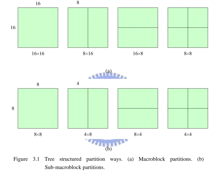
Figure 3.1 Tree structured partition ways. (a) Macroblock partitions. (b) Sub-macroblock partitions. ... 22
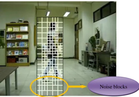
Figure 3.2 An example of noise macroblocks. ... 23
Figure 3.3 The position information of each 8×8 sub-macroblock of a 16×16 macroblock. ... 24
Figure 3.4 An example of the results of applying the range reduction algorithm. The black rectangle is the motion region and the white rectangles are the sub-macroblocks in the region. (a) The first P frame without reduction. (b) The second P frame without reduction. (c) The third P frame without reduction. (d) The 4th P frame without reduction. (e) The first P frame with reduction. (f) The second P frame with reduction. (g) The third P frame with reduction. (h) The 4th P frame without reduction. ... 26
Figure 3.5 An example of selecting candidate motion regions by partition variances. The black rectangle is the candidate motion region and the white rectangles are the sub-macroblocks in the region. (a) The detection result obtained without using partition variances. (b) The detection result obtained by using partition variances. ... 28
Figure 3.6 Ten representing frames of the resulting stego-video. (a) The first frame. (b) The second frame. (c) The third frame. (d) The 4th frame. (e) The 5th frame. (f) The 6th frame. (g) The 7th frame. (h) The 8th frame. (i) The 9th frame. (j) The 10th frame. ... 39
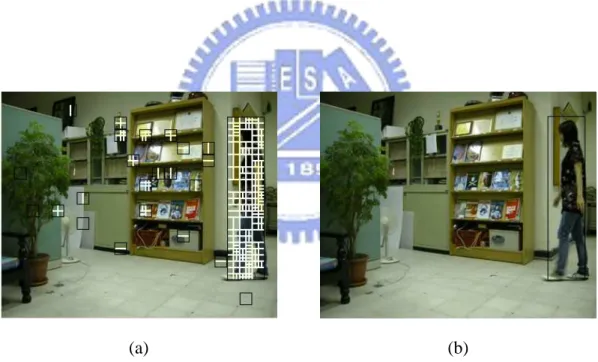
Figure 3.7 The proposed user interface for searching suspicious activities in a surveillance video. ... 41
Figure 3.8 The search result of the bookshelf which is specified by a black rectangle. ... 41
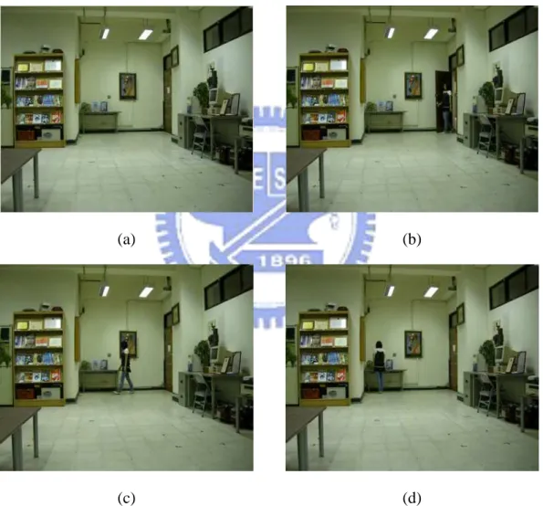
Figure 3.9 Some resulting video clips of the search in Figure 3.8. (a) The first video clip. (b) The second video clip. (c) The third video clip. (d) The 4th video clip. (e) The 5th video clip. (f) The 6th video clip. ... 42
Figure 4.1 An illustration of replacement. ... 46
Figure 4.2 An illustration of cropping. ... 46
Figure 4.3 An illustration of insertion. ... 46
Figure 4.4 The notations of the eight neighboring macroblocks of M. ... 51
Figure 4.5 An example of embedding authentication signals. The region signals of one of the two P frames form authentication signals, and the authentication signals are hidden into the following I frame. (a) The first P frame of the first frame group. (b) The second P frame of the first frame group. (c) The I frame of the first frame group. (d) The first P frame of the second frame group. (e) The second P frame of the second frame group. (f) The I frame of the second frame group. ... 55
Figure 4.6 A comparison between the original I frame and the stego-I frame. (a) The original I frame. (b) The stego-I frame. ... 56
Figure 4.7 Three consecutive frame groups of the original video. (a) A representing P frame of G1. (b) The I frame of G1. (c) A representing P frame of G2. (d) The I frame of G2. (e) A representing P frame of G3. (f) The I frame of G3. ... 68
Figure 4.8 Three consecutive frame groups of the protected video. (a) A representing P frame of G1. (b) The I frame of G1. (c) A representing P frame of G2. (d) The I frame of G2. (e) A representing P frame of G3. (f) The I frame of G3. ... 69
Figure 4.9 Three consecutive frame groups of the tampered video. (a) A representing P frame of G1. (b) The I frame of G1. (c) A representing P frame of G2. (d) The I frame of G2. (e) A representing P frame of G3. (f) The I frame of G3. ... 70
Figure 4.10 Three consecutive frame groups of the authenticated video. The green areas in the right figures are suspicious areas of the I frame. The black rectangles in the left figures are the tree structured macroblock decomposition information of the suspicious areas. (a) A representing P frame of G1. (b) The I frame of G1. (c) A representing P frame of G2. (d) The I frame of G2. (e) A representing P frame of G3. (f) The I frame of G3. ... 71 Figure 5.1 Types of multiple slice groups. The numbers in these figures are the slice
group identifiers. There is another type, Type 6 - explicit mapping which is entirely user-defined. (a) Type 0 - interleaved mapping (three slice groups). (b) Type 1 -dispersed mapping (three slice groups). (c) Type 2 - foreground and background mapping (four slice groups). (d) Type 3 - box-out mapping (two slice groups). (e) Type 4 - raster mapping (two slice groups). (f) Type
5 - wipe mapping (two slice groups). ... 79 Figure 5.2 Six representative frames of an original video. (a) The first frame. (b) The
second frame. (c) The third frame. (d) The 4th frame. (e) The 5th frame. (f) The 6th frame. ... 84 Figure 5.3 Six representative frames of a privacy video. (a) The first frame. (b) The
second frame. (c) The third frame. (d) The 4th frame. (e) The 5th frame. (f) The 6th frame. ... 85 Figure 5.4 Six representative frames of a recovered video. (a) The first frame. (b) The
second frame. (c) The third frame. (d) The 4th frame. (e) The 5th frame. (f) The 6th frame. ... 86 Figure 5.5 Comparison between a original image and the corresponding recovered
LIST OF TABLES
Table 2.1 The way that macroblocks comprise slices ... 11
Chapter 1
Introduction
1.1
Motivation
With the progress of video compression technology and efficient video coding standards, digital videos nowadays have become much more popular than in the past. H.264 is one of the video coding standards, which contains many innovative features, making the resulting coding performance more efficient than previous standards (MPEG-1, MPEG-2, MPEG-4, H.261, H.263, etc.). Because of the efficiency and good quality yielded by H.264, it has been widely used in many different applications, in which video surveillance is especially an important topic because video fidelity and privacy is often seriously concerned with. Therefore, it is necessary to develop effective methods for authenticating and protecting H.264 surveillance videos.
The crime rate rises along with society development, andthe public space needs to be monitored, so the design of environment surveillance systems becomes more and more important. Since a video surveillance system can monitor an environment space for a long period, most frames in the resulting surveillance video are still with the same background. How to find suspicious people or objects quickly in such videos has become a major problem. It is desired to design quick video-content search techniques based on the use of content features, as conducted in this study.
The need of video authentication is especially essential in video surveillance applications. Because surveillance videos usually contain suspicious or unlawful acts,
malicious users may want to acquire the video in an illegal way and tamper with it for misrepresentation. How to protect and authenticate surveillance videos has also become a main topic in the research field of video surveillance. There are two important concerns in the study of video authentication, namely, fidelity and integrity. Embedding invisible authentication signals in a video, which results in a protected
video, is a good approach to resolving the two concerns mentioned above. If a
malicious user tampers with the protected video, the authentication signals hidden in it will be destroyed. By checking the presence of the authentication signals, we can verify the fidelity of the protected video. Furthermore, we may want to understand how and where the protected video has been tampered with; in other words, we may want to validate the integrity of the protected video. From the above reasons, it is necessary to design a good authentication method which not only checks if the video has been tampered with or not, but also shows where and how the tampering occurs. This is also a goal of this study.
Privacy protection is a very important issue in video surveillance. Since a video surveillance system usually monitors a public space for long periods of time, it may possibly record some personal information which violates personal privacy. Hence, it is necessary in some cases to hide the privacy violation parts of the surveillance video content to avoid legal disputes and to protect the personal privacy of non-suspicious people. This is the last of our goals in this study.
1.2
General Review of Related Works
Since digital rights management is more and more important in our daily lives, many works related to video-content search, video authentication, and privacy protection for surveillance videos have been introduced. For video-content search,many motion detection algorithms such as background subtraction, temporal differencing, etc. used to index videos have been proposed. For video authentication, techniques like watermarking, digital signatures, etc. are widely used for authentication. For privacy protection, many different ways to protect personal information, such as scrambling the area containing sensitive information, removing the authorized person, etc., have been proposed. A detailed review of these techniques mentioned above, which have been developed in recent years, will be presented in Chapter 2. In addition, because the proposed techniques in this thesis are applied to H.264 videos, we will also make a review of the H.264 standard in Chapter 2.
1.3
Overview of Proposed Methods
1.3.1
Terminologies
The definitions of some related terminologies used in this study are described as follows.
1. Motion region: a motion region is a detected area which contains motions in
an input video after a motion detection process.
2. Tree structured macroblock decomposition information: tree structured
macroblock decomposition information is the macroblock decomposition information generated in the tree structured motion compensation process of the encoding process of H.264.
3. Protected video: a protected video is a video in which authentication signals
have been embedded.
4. Video authentication: video authentication is a process for verifying the
integrity and fidelity of a suspicious surveillance video.
which might violate privacy after removing personal information.
6. Recovered Privacy-covered area: a recovered privacy-covered area is a part
of video content which might violate privacy obtained after restoring personal information.
1.3.2
Brief Descriptions of Proposed Methods
1.3.2.1
Proposed Method for Video-Content Search in
Surveillance Video
A method of motion detection based on the use of content features is proposed for searching surveillance video contents in this study. By using the tree structured macroblock decomposition information in a motion detection process, regions with moving objects can be detected correctly. After the motion detection process, the content features of the detected motion regions are analyzed and embedded into the video. If a user wants to search the video content, the features embedded in the video previously are extracted to index the video content. In this way, the features provide a fast way to search video contents in a surveillance video.
1.3.2.2
Proposed Method for Authentication for Surveillance
Video
A method using the tree structured macroblock decomposition information in H.264 codes as authentication signals is proposed for video authentication in this study. The macroblock decomposition information is generated during the encoding process and is different for different video contents, so it is suitable for use as authentication signals. If a protected video has been tampered with, the authentication signals will be destroyed as well. Therefore, how and where the protected video is
tampered with can be inspected to carry out the authentication work.
1.3.2.3
Proposed Method for Protection of Personal Privacy
of Surveillance Videos
A method using an information hiding technique is proposed in this study for hiding and recovering video contents containing sensitive personal information. A video can be decoded correctly based on the decoding information including motion vectors and frequency coefficients. Therefore, the original decoding information may be removed from the original video stream and set to some predefined values in order to cover video contents with sensitive privacy information and replace them with background image parts. The removed decoding information is not eliminated but embedded into the video and can be extracted later from the stego-video in case there is a need of retrieving the sensitive contents.
1.4
Contributions
Some contributions made by this thesis are listed in the following.
1. A method of motion detection in videos based on motion information and tree structured macroblock decomposition information in H.264 codes is proposed in this study.
2. A method of data hiding using random encoding mode selection in H.264 videos is proposed.
3. An application of video-content search by scene features is proposed.
4. A video authentication system using tree structured macroblock decomposition information in H.264 codes as authentication signals is proposed.
5. A method is proposed to hide the privacy information of unsuspicious people and restore it in need of retrieving the original video contents.
1.5
Thesis Organization
In the remainder of this thesis, related works about motion detection, video data hiding, video authentication, privacy protection in surveillance videos, and the H.264 standard are reviewed in Chapter 2. In Chapter 3, the proposed method of motion detection and the application of video-content search are described. In Chapter 4, the proposed video authentication system for surveillance videos is described. In Chapter 5, the proposed method of privacy protection of surveillance videos is presented. Finally, conclusions and some suggestions for future works are given in Chapter 6.
Chapter 2
Review of Related Works and H.264
Standard
2.1
Review of Techniques for Motion
Detection
A lot of motion detection techniques have been proposed to detect moving objects in a video [1-5]. The techniques can be classified into two categories. One is for use in the pixel domain [1-2]; the other in the compressed domain [3-4]. Generally speaking, the approaches used in the pixel domain need to fully decode a compressed video bitstream first, but they can be employed in videos coded in different video coding standards. On the other hand, each of the approaches used in the compressed domain can perform a motion detection process by partially decoding a compressed video bitstream, but they can only be employed in videos coded in specific standards.
Haritaoglu et al. [1] proposed a motion detection method based on background subtraction in the pixel domain. They built a statistical model for a background scene that allows them to detect moving objects even when the background scene is not completely stationary. Lipton et al. [2] proposed another approach based on temporal differencing in the pixel domain, which means computation of pixel-wise differences between consecutive video frames. The basic idea of the approach is to compare video frames separated by a constant time to find moving objects. Zeng et al. [3] proposed
another approach in the compressed domain. They employed a block-based Markov random field (MRF) model in a field formed with motion vectors to segment moving objects during a decoding process. The methods mentioned above detect motions by common properties of videos, such as pixel values, motion vectors, etc, but they don’t use special features of a specific standard as the main clues.
2.2
Review of Techniques for Video
Data Hiding
Video data hiding can be used in many applications about videos, such as video watermarking, video authentication, etc. As a result, lots of techniques for video data hiding have been introduced [6-10]. Mobasseri et al. [10] embedded data into the CAVLC code space of an H.264 bitstream, which is one of the existing entropy coding techniques of H.264. This method was directly applied to a bitstream without video decoding or partial decompression. Huang and Tsai [7] proposed a video data hiding method based on the use of prediction modes and tree structured macroblock motion compensation of the H.264 structures. In addition, they also used the Lagrange optimization technique to minimize image distortion yielded by the data hiding process. In Noorkami and Mersereau [6], a robust data hiding algorithm for H.264 was proposed. The basic idea is to embed data by modifying the DC coefficients in luminance residual blocks of the video and employ a human visual model adapted for a 4×4 discrete cosine transform block to increase the payload and robustness while limiting visual distortion. Gong and Lu [8] also proposed a data hiding method in the frequency domain. They employed a texture-masking-based perceptual model to adaptively choose the hiding strength of each block. In an H.264 encoding process, if someone re-encodes a video, the prediction modes in the original video may be
different from the resulting video. As a consequence, if re-encoding is unavoidable, videos using the robust data hiding methods based on the frequency domain will face a critical problem that the frequency coefficients may be different from the original ones with hidden data being modified due to the changes of an intra prediction mode. This problem may cause a loss of hidden information, so we introduce a robust data hiding method which can endure an H.264 re-encoding process.
2.3
Review of Techniques for Video
Authentication
Video authentication plays an important role in a digital rights management system, so many different methods have been proposed to solve the problem [10-13]. Zhang and Ho [11] introduced a video authentication method which makes an accurate usage of the tree structured motion compensation, motion estimation, and Lagrange optimization of the H.264 standard. As mentioned in the paper, authentication information is embedded based on the best mode decision strategy in the sense that if a video undergoes any spatial and temporal attacks, the scheme can detect the tampering by the sensitive mode change. Pröfrock et al. [12] proposed a method using skipped macroblocks of a H.264 video to embed authentication data. The data are embedded as a fragile, blind and erasable watermark with low video quality degradations. In contrast with other authentication methods, the embedding process is done after an H.264 compression process, while others are done during the process. The methods mentioned above usually use additional authentication information to authenticate videos. How to authenticate videos without external information is an interesting research topic and is investigated in this study.
2.4
Review of Techniques for Privacy
Protection in Videos
Privacy protection has become more and more important along with the rise of video surveillance systems. Many different approaches have been introduced in recent years [14-16]. Meuel et al. [14] introduced a method to protect faces in surveillance videos. As mentioned in the method, any visible information of faces in a video is deleted and embedded in the video that allows further reconstruction of the faces if needed. In Dufaux et al. [15], the regions containing personal information are scrambled. As a consequence, the scene remains visible, but the privacy-sensitive information is not identifiable. Zhang et al. [16] proposed another method to protect authorized persons, which are not only removed from a surveillance video, but also embedded into the video. The above-mentioned methods are based on a concept which is to protect privacy of authorized persons, so the protected persons must be recognized first by manpower. If there are many persons requiring recognition, it will become a tedious job. We call this kind of methods as object-based privacy protection. In order to solve this problem, we introduce a region-based privacy protection method to avoid recognizing authorized persons by hand. Besides, an authorized user can define the protected region easily.
2.5
Review of H.264 Standard
2.5.1
Structure of H.264 standard
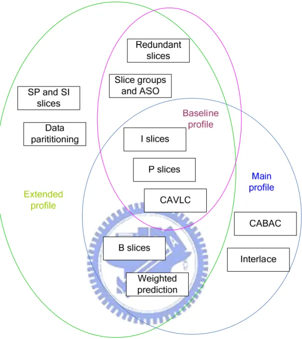
The H.264 standard defines three profiles: Baseline, Main, and Extended, which provide different sets of coding functions and different components required by an
encoder or decoder. Because of the individual features of each profile, there are many different potential applications of these three profiles. The applications of the baseline profile include video telephony, video conferencing, and wireless communications; the applications of the main profile include television broadcasting and video storage; and the extended profile may be particularly useful for streaming media applications. The relation between these profiles is illustrated in Figure 2.1. H.264 videos have a hierarchical structure. A video sequence consists of consecutive video images (frames). A video image is composed of at least one slice. There are five slice types: intra slice (I), predicted slice (P), bi-predicated slice (B), switching P slice (SP), and switching I slice (SI). Generally speaking, the first three slice types are the main slice types which are widely used in H.264 videos. A slice is composed of macroblocks, which can be categorized into four types including I, P, B, and skipped. I macroblocks are predicted by previously encoded and reconstructed blocks in the same slice. P macroblocks are predicted by previously encoded samples before the current frame in temporal order. B macroblocks are predicted by encoded samples before or after the current frame. Skipped macroblocks of the P slice is transmitted with motion vectors but not with frequency coefficients. Skipped macroblocks of the B slice is transmitted without both motion vectors and frequency coefficients. How the macroblocks comprise the slices is illustrated in Table 2.1.
Table 2.1 The way that macroblocks comprise slices I macroblocks P macroblocks B macroblocks
Skipped macroblocks I slice √
P slice √ √ √ B slice √ √ √
Figure 2.1 Relation between the Baseline, Main, Extended profiles.
2.5.2
Process of Encoding
Before describing the process of encoding of H.264 videos, we introduce the concept “prediction” first. Because a video sequence is formed by consecutive similar images, there is a lot of coding redundancy. How to use the high correlation between these similar images to reduce the redundancy has become a main topic in the video compression research field. The basic idea of prediction is to find a block which is the most similar to the current block and to save the difference between the two. There
are two models of prediction: intra mode and inter mode. The intra mode uses the similarity between pixel samples in the same frame and the inter mode uses the similarity between different frames.
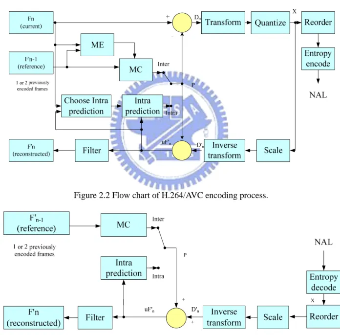
The process of encoding of H.264 videos is illustrated in Figure 2.2. There are a forward path and a reconstruction path in the figure. In the forward path, an input frame Fn is processed in units of a macroblock. Each macroblock is encoded in intra
or inter mode and can be sub-partitioned into sub-macroblocks. For each sub-macroblock in the macroblock, a prediction P is formed based on previously encoded, decoded, and reconstructed samples. In the intra mode, P is formed from the samples in the current slice. In the inter mode, P is formed by the samples in the past or future frames which can also be called reference frames. The difference between P and the current sub-macroblock is used to produce a residual sub-macroblock that is DCT-based transformed and quantized. The resulting frequency coefficients are reordered and entropy encoded. The coefficients after entropy coding and other information required in a decoding process (prediction modes, motion vectors, etc.) form the compressed bitstream which is passed to a Network Abstraction Layer (NAL) for transmission or storage usage. In the reconstruction path, the encoder decodes (reconstructs) the previously encoded data to provide a reference for further predictions. The encoded data is inverse transformed to produce a difference sub-macroblock and the prediction block P is added to the difference sub-macroblock to create a reconstructed sub-macroblock which is a decoded version of the original sub-macroblock.
2.5.3
Process of Decoding
the data elements to produce quantized coefficients. Then these coefficients are inversely transformed to yield a difference sub-macroblock. Using the decoding information retrieved from the bitstream, the decoder creates a prediction sub-macroblock P which is identical to the original prediction sub-macroblock in the encoder. P is added to the difference sub-macroblock to produce a decoded sub-macroblock. The flow chart of the decoding process is illustrated in Figure 2.3.
Figure 2.2 Flow chart of H.264/AVC encoding process.
2.5.4
Tree Structured Motion Compensation
Motion compensation is the process of finding the best prediction block in inter mode. In all video standards except H.264, the processing unit of motion compensation is a whole macroblock. H.264 introduces a novel feature: tree
structured motion compensation. The basic concept is that a macroblock can be
divided into sub-macroblocks and each of the sub-macroblocks is motion compensated individually. Macroblocks can be partitioned in different modes for different video contents.
Each 16×16 macroblock may be partitioned and motion compensated by one of the following ways: one 16×16 macroblock partition, two 16×8 partitions, two 8×16 partitions, and four 8×8 partitions, as illustrated in Figure 2.4. If the 8×8 mode is chosen, each of the four 8×8 sub-macroblocks in the macroblock may be further partitioned in four ways: one 8×8 sub-macroblock partition, two 8×4 sub-macroblock partitions, two 4×8 sub-macroblock partitions, and four 4×4 sub-macroblock partitions, as illustrated in Figure 2.5. This method of partitioning macroblocks into motion compensated sub-macroblocks of varying sizes gives rise to a large number of possible combinations in each macroblock.
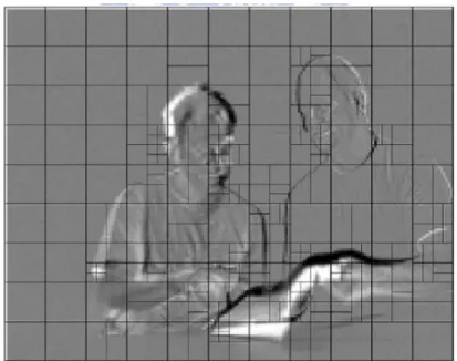
Each sub-macroblock requires a separate motion vector. Choosing a large partition size (16×16, 16×8, 8×16) means that a small number of bits are needed to transmit the motion vector(s) and the partition mode(s) but the motion compensated residual may be a large number in detailed frame areas. Choosing a small partition size (8×4, 4×4, etc.) may result in a small residual but needs a larger number of bits to transmit the motion vectors and the partition modes. In general, a large partition size is appropriate for smooth frame areas while a small partition size is suitable for detailed areas, as illustrated in Figure 2.6.
8×8 4×8 8×4 4×4 8 8 4 16×16 8×16 16×8 8×8 16 16 8
Figure 2.6 An example of tree structured motion compensation. Figure 2.5 Sub-macroblock partitions.
2.5.5
Intra Prediction Modes
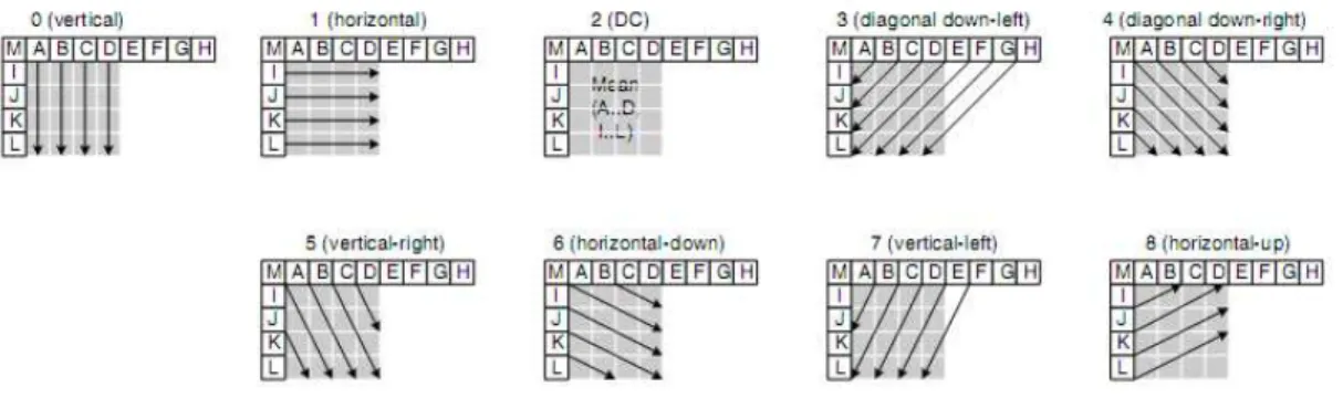
Within an intra macroblock of an H.264 video, a 4×4 sub-macroblock is a unit of processing in intra prediction. Thirteen pixel samples are formed by previously encoded and reconstructed blocks. As illustrated in Figure 2.7, A, B, C and D are from the upper neighboring block; E, F, G and H are from the upper-right neighboring block; I, J, K and L are from left neighboring block, and M is from the upper-left neighboring block. There are nine prediction modes for the thirteen pixel samples to form the prediction block of the current processing 4×4 block. The nine modes of intra prediction are illustrated in Figure 2.8. The prediction block is subtracted from the current block to create the residual block. The encoder selects the best mode of intra prediction that performs the lowest cost of encoding.
Figure 2.7 The prediction block and the thirteen samples.
Chapter 3
Searches of Video Contents for Scene
Surveillance by Novel Uses of H.264
Coding Features
3.1
Introduction
Since a surveillance video system usually monitors a space for a long period, it may record lots of suspicious people or activities. If someone wants to check whether a surveillance video contains illegal activities, it will often take him/her a very long time to search the whole video for the specific activities or involved people. In this chapter, we describe the proposed method of video-content search by a novel use of H.264 coding features to avoid tedious search on recorded videos. With such a video-content search method, it will become much easier and faster to check any suspicious activity or people in recorded videos.
In Section 3.1.1, some definitions related to the video-content search problem are described, and the proposed idea and system configuration are given in Section 3.1.2. In Section 3.2, a motion detection algorithm based on the proposed idea is introduced. In Section 3.3, the way we use for embedding the motion region information is described. In Section 3.4, the process of extraction of motion region information is presented. Some experiment results are shown in Section 3.5. In Section 3.6, the last section of this chapter, some discussions and summary are given.
3.1.1
Problem Definition
In the video-content search problem dealt with in this study, the activities recorded in an input video are detected and embedded back into the video for later search. Two issues are involved in this problem. The first is how to detect motion regions correctly in a video taken by a real-time surveillance system with a stationary camera. Motion detection is a very popular research topic in video analysis and can be implemented in many different ways as described in Chapter 2. The second issue is how to embed information about the detected motion regions into an H.264 compressed bitstream during an encoding process and how to extract them during a decoding process.
3.1.2
Proposed Idea
In the proposed method, each frame captured from a stationary camera is encoded into a compressed bitstream in the H.264 encoding process. During the encoding process, a novel motion detection technique is used in this study to detect suspicious activities in the currently-processed frame. While the motion regions are detected, the location information of the motion regions is embedded into the quantized frequency domain of the compressed H.264 bitstream. Therefore, if someone wants to know whether a specific region of a video contains suspicious activities or not, the data extraction process in the proposed method can be utilized to search the video contents and output the video clips that the user is interested in.
3.2
Detection of Motion Regions by
H.264/AVC Coding Features
In the proposed system, we introduce a novel motion detection technique by use of H.264 coding features. In Section 3.2.1, the idea of the proposed technique is stated. And in Section 3.2.2, the detailed process of the proposed motion detection technique is described.
3.2.1
Proposed Idea of Motion Detection Technique
As mentioned in Chapter 2, in an encoding process of a P or B slice of a compressed video stream, an H.264 encoder needs to find the best partition mode of the currently processed macroblock. Each 16×16 macroblock may be partitioned and motion compensated by one of the following ways: one 16×16 macroblock partition, two 16×8 partitions, two 8×16 partitions, and four 8×8 partitions, as illustrated in Figure 3.1(a). If the 8×8 mode is chosen, each of the four 8×8 sub-macroblocks in the macroblock may be further partitioned in four ways: one 8×8 sub-macroblock partition, two 8×4 sub-macroblock partitions, two 4×8 sub-macroblock partitions, and four 4×4 sub-macroblock partitions, as illustrated in Figure 3.1(b).
For the same macroblock, different partition modes produce different coding costs to the compressed video stream. If the encoder does not choose the best partition mode for the current macroblock, it will cause more bits to be included in the stream. Therefore, the encoder does so according to the video content of the currently-processed macroblock to get the lowest coding cost. Generally speaking, the partition modes with large partition sizes (16×16, 16×8, 8×16) are suitable for smooth areas, while the modes with small partition sizes (8×8, 8×4, 4×8, 4×4) are appropriate for detailed areas.
Video contents of motion regions usually change greatly both in the time domain and in the spatial domain. In the time domain, the movements in the motion regions result in a lot of information of changes, which needs to be described. In the spatial domain, the motion regions may contain some moving objects which might be humans, cars, etc. These moving objects might contain lots of details that need to be encoded.
Changes in the time domain generally make the partition sizes of the motion regions to be small ones in order to reduce the coding cost calculated in the motion compensation process. Therefore, the partition modes of the motion regions are mostly with small partition sizes. Moreover, changes in the spatial domain make the partition modes of the macroblocks within the motion regions variable, because video contents between these macroblocks are quite different from each other.
Based on the clues mentioned above, we choose to use small partition sizes and variable partition modes as features of motion regions, and use them and motion vectors to detect motion regions in surveillance videos.
Besides, after detecting motion regions by these features, some noise caused by lights and shadows might be included in the detected motion regions and appears on the fringes of the regions. We call macroblocks containing such noise in the detected motion regions as noise macroblocks. Partition modes of these noise macroblocks usually include large partition sizes; Therefore, we also use this characteristic to eliminate the noise. An example of noise macroblocks is illustrated in Figure 3.2.
3.2.2
Process of Detection of Motion Regions
The proposed motion detection method is applied to frames composed of P slices only. During the encoding process of an input frame, the length of every motion
16×16 8×16 16×8 8×8 16 16 8 8×8 4×8 8×4 4×4 8 8 4
vector of a sub-macroblock of the input frame is compared with a pre-defined threshold in order to filter motion-less sub-macroblocks. The remaining sub-macroblocks are called motion blocks.
(a)
(b)
We obtain candidate motion regions by applying a region growing algorithm to the motion blocks. The basic concept of the region growing algorithm is to check the eight neighboring 16×16 macroblocks M1 through M8 around each 16×16 macroblock
where the motion blocks are located. If any of M1 through M8, say Mi, contains
motion blocks, we check further the eight neighboring 16×16 macroblocks of Mi, and
so on recursively, until reaching the boundary of the input frame.
Figure 3.1 Tree structured partition ways. (a) Macroblock partitions. (b) Sub-macroblock partitions.
Since there may be noise caused by lights and shadows on the fringes of each candidate region, a range reduction algorithm is introduced to eliminate the noise. The basic idea is that the partition mode of the noise macroblock is usually a large partition size (16×16, 16×8, 8×16) and appears on a fringe. So, we try to shrink most fringes composed of large partition sizes in the range reduction algorithm.
While obtaining these reduced candidate regions, we perform a process to calculate partition variances of these regions. To calculate the partition variances, we quantify in advance the partition modes of the motion blocks of these regions by assigning each of them a value called a quantification value based on the mode numbers defined in an H.264 encoder and position information illustrated in Figure 3.3. The position information is defined based on transforming the two dimensional coordinates of each 8×8 sub-macroblock within a 16×16 macroblock into one dimensional. We then use the quantification value of each motion block to calculate the partition variance of each candidate motion region. The detail will be described
Figure 3.2 An example of noise macroblocks.
later. Each candidate region is evaluated finally by the partition variance. The larger the variance, the more possible for the candidate region to be a motion region.
Algorithm 3.1. Motion detection process.
Input: a frame F composed of P slices only, a motion vector threshold Tm, and a
variance threshold Tv.
Output: position information about the motion regions in F. Steps:
1. For each sub-macroblock Ms in F, if the length of the motion vector of Ms is
larger than Tm, then decide Ms as a motion block.
2. Perform the region growing algorithm to group the motion blocks in F to form several candidate motion regions. Circumscribe each candidate with a rectangle. 3. Reduce the range of each candidate motion region R by shrinking each edge E of
the rectangle of R according to the following steps.
3.1 Define a set S for E, which includes motion sub-macroblocks of 16×16 macroblocks in contact with E.
3.2 For each motion block Be in S, compare the length Le of its motion vector
with the mean Lm of the lengths of the motion vectors of all the motion
Figure 3.3 The position information of each 8×8 sub-macroblock of a 16×16 macroblock.
2 1
blocks in S. If Le is larger than Lm and the partition mode of Be is a small
partition size mode, jump back to Step 3.1 to skip shrinking edge E and to continue processing the next set S.
3.3 After checking all the motion blocks in S in Step 3.2, count the number of motion blocks of large partition sizes of S. If the number is over a half of the total number of motion blocks of S, shrink the edge E for 16 pixels. 3.4 Go to Step 3.1 to process the next edge until all edges of R have been
processed.
4. Calculate the partition variance V of each reduced region R′ of R according to the following steps.
4.1 Assign each motion block BR in R′ a quantification value according to the
partition mode number Nmode defined in the encoder and the position
information Pos of BR in the following way:
mode mode
if the partition size is small, set quantificaiton value N Pos; if the partition size is large, set quantificaiton value N .
= +
= (3.1)
4.2 Use the quantification values of the motion blocks to calculate the variance
V of R′.
5. If V is larger than Tv, put R′ into a candidate list L; otherwise, find a block B in
the region R′ which has the largest motion vector length. If the location of B is inside the motion regions of the previous frame, put R′ into the list L, too; otherwise, drop R′.
6. Perform a merge process to the remaining regions in L according to the following rules.
6.1 If there are regions which belong to the same motion region in the previous frame, merge these regions.
6.2 If there are overlapping regions, merge them.
7. Output the position information of the motion regions remaining in L after the merge process.
The above algorithm shrinks edges by counting the number Ne of motion blocks
of large partition sizes in each edge E. If Ne is larger than a half of the total number of
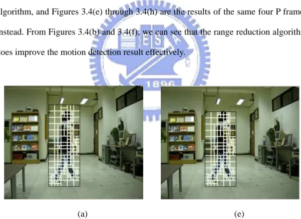
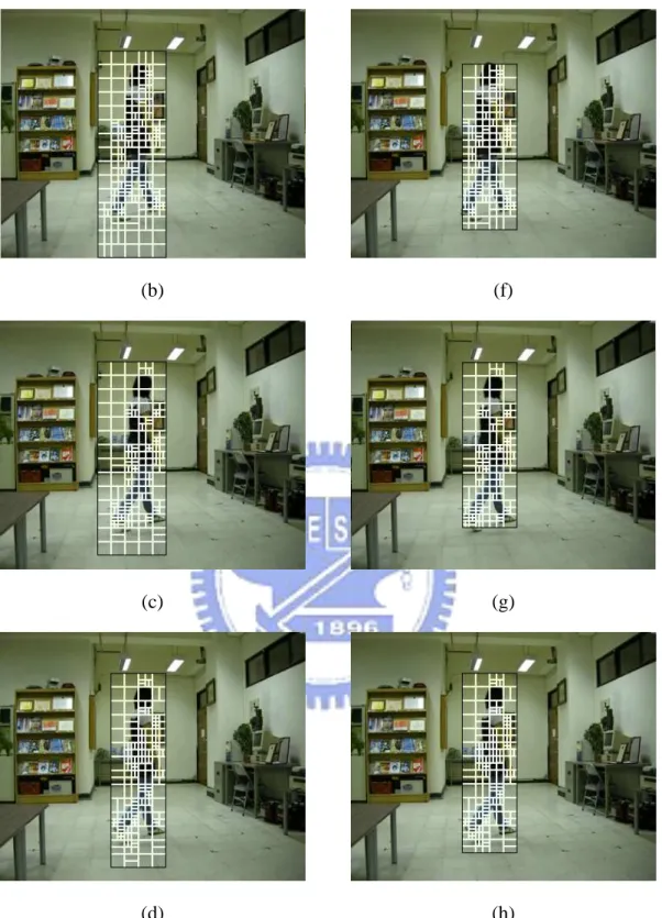
motion blocks in E, E is shrunk because the overall composition of E is the large partition size. An example of the results obtained from applying the range reduction algorithm is illustrated in Figure 3.4, in which Figures 3.4(a) through 3.4(d) are the motion detection results of four consecutive P frames without performing the algorithm, and Figures 3.4(e) through 3.4(h) are the results of the same four P frames instead. From Figures 3.4(b) and 3.4(f), we can see that the range reduction algorithm does improve the motion detection result effectively.
(a) (e)
Figure 3.4 An example of the results of applying the range reduction algorithm. The black rectangle is the motion region and the white rectangles are the sub-macroblocks in the region. (a) The first P frame without reduction. (b) The second P frame without reduction. (c) The third P frame without reduction. (d) The 4th P frame without reduction. (e) The first P frame with reduction. (f) The second P frame with reduction. (g) The third P frame with reduction. (h) The 4th P frame without reduction.
(b) (f)
(c) (g)
(d) (h)
Figure 3.4 An example of the results of applying the range reduction algorithm. The black rectangle is the motion region and the white rectangles are the sub-macroblocks in the region. (a) The first P frame without reduction. (b) The second P frame without reduction. (c) The third P frame without reduction. (d) The 4th P frame without reduction. (e) The first P frame with reduction. (f) The second P frame with reduction. (g) The third P frame with reduction. (h) The 4th P frame without reduction (continued).
In the process of assigning quantification values to motion blocks, we calculate the quantification values based on the mode numbers which have been defined in the encoder. Moreover, motion regions are mostly composed of small partition sizes (8×8, 8×4, 4×8, 4×4), so a macroblock in a motion region may be partitioned into many small sub-macroblocks. Therefore, for the motion blocks with small sizes, the quantification values are determined not only by mode numbers but also by position information defined in Figure 3.3 in order to distinguish different combinations of these small sub-macroblocks and increase the variety of the quantification values. An example is illustrated in Figure 3.5 in which Figure 3.5(a) is the detection result without utilizing the partition variances, and Figure 3.5(b) is the result instead.
(a) (b)
Figure 3.5 An example of selecting candidate motion regions by partition variances. The black rectangle is the candidate motion region and the white rectangles are the sub-macroblocks in the region. (a) The detection result obtained without using partition variances. (b) The detection result obtained by using partition variances.
3.3
Embedding and Extracting Data in
H.264 Videos
DCT-based data hiding methods are commonly used for videos and images. In video standards before H.264 is introduced, the DCT-based methods are the basis of many applications related to videos. However, while re-encoding, the DCT-based methods face a problem that different intra prediction modes cause different sets of frequency coefficients. Therefore, we introduce an improved DCT-based data hiding method suitable for H.264 videos. In Section 3.3.1, the proposed technique of embedding data is introduced. In Section 3.3.2, the proposed technique of extracting data is described.
3.3.1
Process of Embedding Data
In this section, we introduce the method of embedding data. The proposed idea is described in Section 3.3.1.1. In Section 3.3.1.2, the detailed algorithm is stated.
3.3.1.1
Proposed Idea
While an H.264 encoded stego-video is re-encoded, the resulting intra prediction modes may be distinct from the original ones. Hence, the data hidden in the frequency domain in this video may be lost because the resulting frequency coefficients could be different. As a result, we introduce a secret-key-based data hiding method. A secret key designated by a user is used to generate intra prediction modes used in data hiding in order to prevent the hidden data from being lost. The modes generated in the data hiding process will not affect the normal encoding procedure.
3.3.1.2
Detailed Algorithm
The proposed data hiding method deals with frames composed of I slices only. Each 4×4 sub-macroblock of an I frame is used to hide one bit of data. The data hiding process is performed before the encoding process. A secret key is utilized as the seed of a random number generation. The result of the random number generation is used to decide an intra prediction mode P of each 4×4 sub-macroblock. A residual block generated based on P is transformed and quantized. The resulting frequency coefficients are modified to hide one bit of data and inverse transformed to produce a reconstructed block which substitutes the original 4×4 sub-macroblock. The encoder continues to encode this stego 4×4 sub-macroblock. In more details, P will not affect the normal encoding process and the prediction mode decided by the encoder is still the best prediction mode yielding the lowest coding cost.
Algorithm 3.2. The process of hiding a 16×16 macroblock in an H.264 video frame
composed of I slices only.
Input: a secret key R, binary data D to be hidden, a 16×16 macroblock M16, and a
random number generator f.
Output: a stego macroblock M16′.
Steps:
1. Use the input secret key R as a seed for f to generate a sequence of random numbers.
2. Perform the following steps before M16 is encoded.
2.1 For a 4×4 sub-macroblock M4 in M16, select one of the available intra
prediction modes Mode of M4 according to the result of the random number
2.2 Use Mode to produce a prediction block Mp and subtract it from M4 to
generate a residual block Mr.
2.3 Transform Mr into the frequency domain to get the corresponding frequency
coefficients of M4 in the form of a 4×4 block, Coeff.
2.4 Modify Coeff in order to hide an un-hidden bit B of D according to the following rules.
2.4.1 Select the coefficient pair C1(0, 3) and C2(3, 0) in Coeff.
2.4.2 Modify C1 and C2 according to the following equations:
(1). if B = 0: 1 2 2 1 if C > C , swap C and C ; (3.2) (2). if B = 1: 2 1 1 2 2 1 2 1, if C = C , C = C +T; if C > C , swap C and C (3.3)
where T is a pre-defined threshold.
2.5 Inverse transform Coeff and add the result to Mp to produce a reconstructed
4×4 sub-macroblock Mc, which is then taken to replace the original 4×4
sub-macroblock.
3. Repeat Step 2 until all 4×4 sub-macroblock in M16 are processed or until the data
in D to be hidden are all processed.
4. Take the modified macroblock M16′ as input to the normal encoding process.
3.3.2
Process of Extracting Data
In this section, we introduce the proposed data extraction technique. The proposed ideas are described in Section 3.3.2.1. In Section 3.3.2.2, the detailed algorithm for it is presented.
3.3.2.1
Proposed Idea
The proposed method extracts data in a decoder. While the decoder performs a decoding process, we can use a secret key to select an intra prediction mode for each 4×4 sub-macroblock of a reconstructed macroblock. These intra prediction modes can produce sets of frequency coefficients. The hidden data can be extracted from these frequency coefficients.
3.3.2.2
Detailed Algorithm
When the video decoder decodes a macroblock to produce a reconstructed macroblock, a prediction sub-macroblock is formed for each 4×4 sub-macroblock of the reconstructed macroblock based on a prediction mode selected by a secret key. The prediction sub-macroblock is subtracted from the reconstructed 4×4 sub-macroblock to produce a residual block which is then DCT-based transformed to a set of frequency coefficients. The hidden data can be extracted from these sets of frequency coefficients. The details are described in the following algorithm.
Algorithm 3.3. The process of data extraction from a 16×16 macroblock in an H.264
video frame composed of I slices only.
Input: a 16×16 macroblock M16, a secret key R, and a random number generator f.
Output: 16 bits of data hidden in M16.
Steps:
1. Use the input secret key R as a seed for f to generate a sequence of random numbers.
2. Perform the following steps after M16 is decoded.
according to the result of the random number generation. 2.2 Use P to produce a prediction block P′.
2.3 Subtract P′ from M4i to produce a residual block R.
2.4 Transform R into a set of frequency coefficients Coeff.
2.5 Extract the hidden data bit(i) of M4i from Coeff according to the following
equation:
2 1 ( ) 0
( ) 1,
if C C , set bit i = ; else, set bit i =
≥
(3.4) where C1 is the frequency coefficient C1(0, 3) and C2 is C2(3, 0).
3. Repeat Step 2 until all 4×4 sub-macroblock of M16 are processed.
4. Combine all bit(i) of M4i to form the 16 bits of the extracted data as output.
3.4
Embedding of Motion Region
Information
In this section, we introduce a technique for embedding motion region information into I frames during an encoding process. In Section 3.4.1, the principle of the proposed embedding process of motion region information is given, and the detailed algorithm of the embedding process is described in Section 3.4.2.
3.4.1
Principle of Proposed Technique
In the proposed system, the motion region information will be taken as input into the H.264 encoding process while there are motions detected. The input information is embedded into the H.264 video by the data hiding method introduced previously. The embedded information is used to index the surveillance video for the subsequent search process. Because the motion of most moving objects will last for several
frames, we divide the video sequence into frame groups formed with several consecutive frames composed of P slices only, called P frames, and one frame composed of I slices only, called I frame. One of the consecutive P frames is taken as input to the motion detection process and the resulting detection information is embedded into the I frame belonging to the same group if there are motions detected in this group.
3.4.2
Process of Embedding Motion Region
Information
We divide the input video into several frame groups, and each is composed of some P frames and one I frame. We then apply the motion detection process on these P frames and if there are motions detected in these P frames, the location information of these motion regions forms a string I. Since the motion of most moving objects usually last for several frames, we do not hide motion region information of every P frames in the group. We select just one of these P frames, in which the motion regions have covered larger areas in these P frames to represent this group. The string is then transformed into a binary form Ib and embedded into the I frame in the same group.
Each bit of Ib is embedded into a 4×4 sub-macroblock in the frequency domain. As
mentioned above, we randomly select an intra prediction mode to decide which set of frequency coefficients is used to hide the data.
Algorithm 3.4: The process of embedding motion region information.
Input: a secret key R, moving region information M, a random number generator f,
and an I frame F.
Steps:
1. Denote the binary form of M as Mb = b1b2b3…bL, where L represents the length of
Mb.
2. Use the input secret key R as a seed for f to generate a sequence of random numbers.
3. Take out consecutive 16 bits of Mb, which have not been hidden, and denote these
data bits as Mb16.
4. Perform the following steps before the currently-processed macroblock MB is encoded.
4.1 For a 4×4 sub-macroblock MB4 in MB, select one of the available intra
prediction modes Mode of MB4 according to the result of the random
number generation.
4.2 Use Mode to produce a prediction block MBp and subtract it from MB4 to
generate a residual block MBr.
4.3 Transform MBr into the frequency domain to get the corresponding
frequency coefficients of MB4 in the form of a 4×4 block, Coeff.
4.4 Hide an un-hidden bit B of Mb16 into Coeff according to the following rules.
4.4.1 Select the coefficient pair C1 (0, 3) and C2 (3, 0).
4.4.2 Modify C1 and C2 according to the following rule:
(1) if B = 0: 1 2 2 1; if C > C , swap C and C (3.5) (2) if B = 1: 2 1 1 2 2 1 2 1, if C = C , C = C +T; if C > C , swap C and C (3.6)
where T is a pre-defined threshold.
reconstructed 4×4 sub-macroblock Mc, which is then taken to replace the
original 4×4 sub-macroblock.
5. Repeat Step 4 until all 4×4 sub-macroblock in MBare processed or until the data in Mb16 to be hidden are all processed.
6. Jump to Step 3 and repeat the following steps until reaching the last macroblock of F or the end of M.
3.5
Extraction of Motion Region
Information
In this section, we introduce a method for extracting motion region information during a decoding process. In Section 3.5.1, the principle of the proposed process of extracting motion region information is given, and the detailed algorithm of the extraction process is described in Section 3.5.2.
3.5.1
Principle of Proposed Technique
A compressed stego-video is recorded by the proposed system. Before searching motion motions in the resulting surveillance video, the motion region information must be extracted first. A secret key is used to form a seed of a random number generation. Extraction of the information hidden in the frequency domain is performed based on the result of the random number generation.
3.5.2
Process of Extraction of Motion Region
Information
sub-macroblock of the current I frame, an intra prediction mode chosen by the result of the random number generation produces a set of frequency coefficients. Each bit of hidden motion region information is extracted from the set of frequency coefficients. The extraction process continues until reaching the end mark of the motion region information or the last macroblock of the current I frame.
Algorithm 3.5. The process of extracting motion region information. Input: a stego-I frame F, a secret key R, and a random number generator f. Output: motion region information of the frame group F belonging to. Steps:
1. Use the input secret key R as a seed for f to generate a sequence of random numbers.
2. Perform the following steps after the currently-processed 16×16 macroblock M16
is decoded in the decoding process.
2.1 For a 4×4 sub-macroblock M4i of M16, select an intra prediction mode P
according to the result of the random number generation. 2.2 Use P to produce a prediction block P′.
2.3 Subtract P′ from M4i to produce a residual block R.
2.4 Transform R to a set of frequency coefficients Coeff.
2.5 Extract the hidden data bit(i) from Coeff according to the following equation: 2 1 ( ) 0 ( ) 1 if C C , bit i = ; else, bit i = , ≥ (3.7) where C1 is the frequency coefficient C1(0, 3) and C2 is C2(3, 0).
3. Repeat Step 2 until all 4×4 sub-macroblocks of the current macroblock are processed or until the end mark of motion region information is reached.
4. Continue processing the next macroblock until reaching the end mark of the motion region information or the last macroblock of this frame.
5. Combine each bit(i) of M4i to get the motion region information and output.
3.6
Experimental Results
In our experiments, each image captured by a video camera is encoded by an H.264 encoder to form an H.264 compressed surveillance video with frame size 352×288. We simulate a surveillance system composed of a video camera and a notebook computer. A surveillance video of the computer vision lab is taken as an input video. The contents of this video are that a person enters the lab and walks around. Ten representing frames of the resulting stego-video are shown in Figure 3.6. The proposed user interface for searching suspicious activities in a surveillance video is shown in Figure 3.7. If we want to know whether the person has been appeared around the bookshelf, we can specify a region containing the bookshelf and press the search button. Then, the related video clips will be shown in a few milliseconds. The search result of the specific region is shown in Figure 3.8. Some video clips of the result are shown in Figure 3.9.
This experiment shows that the proposed system can help a user search video clips that he or she may be interested in quickly and prevent him or her from go through the whole video to find a short video clip.
3.7
Discussions and Summary
In this chapter, we have proposed a motion detection method using tree structured macroblock decomposition information, a data hiding method suitable for H.264 videos, and a surveillance video search system. The proposed motion detection