Obstacle Avoidance in Person Following for
Vision-Based Autonomous Land Vehicle
Guidance Using Vehicle Location
Estimation and Quadratic
Pattern Classifier
Ching-Heng Ku and Wen-Hsiang Tsai, Senior Member, IEEE
Abstract—An obstacle avoidance method for use in person fol-lowing for vision-based autonomous land vehicle (ALV) guidance is proposed. This method is based on the use of vehicle location estimation and a quadratic pattern classifier, and aims to guide the ALV to follow a walking person in front by navigating along a derived collision-free path. Before generating the collision-free path, the person’s location is obtained from extracted objects in the image by a person detection method. The object closest to a predicted person location is regarded as the followed person and the remaining objects are regarded as obstacles. The collision-free navigation path is designed for ALV guidance in such a way that the ALV not only can keep following the person but also can avoid collision with nearby obstacles. The navigation path results from a quadratic classifier that uses the vehicle and all of the objects in the image as input patterns. A turn angle is then computed to drive the ALV to follow the navigation path. Successful navigation sessions confirm the feasibility of the approach.
Index Terms—Autonomous land vehicle guidance, obstacle avoidance, person following, quadratic pattern classifier, vehicle location estimation.
I. INTRODUCTION
I
N RECENT years, many approaches to autonomous land vehicle (ALV) guidance in indoor and outdoor environments have been developed. How to guide the ALV to navigate by following a walking person in a certain environment and avoid obstacles in the mean time is the major goal of this paper.In the study of obstacle avoidance, some vision-based navi-gation methods [1], [2] for mobile robots with obstacle avoid-ance capability have been proposed. Ohya [1] used a model edge map for vehicle navigation on a planned path. Obstacles are detected by computing the difference between the edges es-timated from the three–dimensional (3-D) environment model
Manuscript received September 14, 1999; revised October 2, 2000. Abstract published on the Internet November 15, 2000.
C.-H. Ku was with the Department of Computer and Information Science, National Chiao Tung University, Hsinchu, Taiwan 300, R.O.C. He is now with the Division of System and Networking, National Center for High-Performance Computing, National Science Council, Hsinchu, Taiwan, R.O.C.
W.-H. Tsai is with the Department of Computer and Information Science, National Chiao Tung University, Hsinchu, Taiwan 300, R.O.C. (e-mail: [email protected]).
Publisher Item Identifier S 0278-0046(01)01130-3.
and the edges detected from the actual camera image. The nav-igation system developed by Lorigo, et al. [2] consists of three independent vision modules, an edge module, an RGB module, and a hue, saturation, value (HSV) module, for obstacle de-tection. The obstacle boundaries from the individual modules are combined into a single obstacle boundary which is con-verted to motor commands. Yang [3] used an adaptive-network-based fuzzy classifier to define 3-D obstacle regions that must be avoided. Biewald [4] used a human-like concept and a more qualitative world model to plan routes. Ku and Tsai [5] used a quadratic classifier in pattern recognition for collision avoid-ance in ALV navigation in an unknown indoor environment.
When a vision-based ALV navigates by following a person walking in front, the person has to be detected first from the image captured by a camera. Although the image of the person is also detected in some pedestrian tracking systems, the approaches [6]–[8] to detecting a pedestrian using the difference between two consecutive images cannot be used in a person-following system. The image for pedestrian tracking is acquired using a stationary charge-coupled-device (CCD) camera. The difference between two consecutive images contains the information of the moving person. However, the camera used in person following is mounted on the ALV and moved along the path of the ALV. The moving person cannot be detected using the image difference information when the camera is not stationary.
On the other hand, after the relative position of the person to the ALV is calculated, a trajectory for the ALV need be generated to obtain the turn angle of the front wheels of the ALV. Some trajectory planning approaches [9]–[11] have been proposed. Munoz and Ollero [9] combined a kinematic visibility graph planning method, a path generation algorithm based on beta-spline curves, and a cubic spline speed profile definition technique to propose a smooth trajectory planning method for mobile robots. Shiller and Serate [10] proposed a trajectory planning method for computing the track forces and track speeds of planar tracked vehicles required to follow a given path at specified speeds on horizontal and inclined planes. Ku and Tsai [11] used sequential pattern recognition techniques for ALV smooth navigation by person following. These methods do not consider the existence of obstacles.
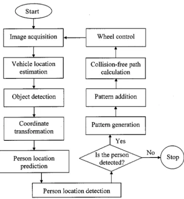
Fig. 1. System flow chart.
In this paper, an obstacle avoidance method for use in person following for vision-based ALV guidance using vehicle location estimation and quadratic pattern classifier design is proposed. This method aims to guide the ALV to follow a walking person in front along a corridor with obstacles. This goal is achieved in this study by guiding the ALV to navigate along a derived collision-free path. First, the translation of the ALV location at the current sampling instant relative to that at the previous sam-pling instant is estimated using the ALV control information. The translation is then used together with previous person loca-tions with respect to the vehicle location at the previous pling instant to predict the person location at the current sam-pling instant. After all of the objects appearing in the image are extracted, the object closest to the predicted person location is regarded as the followed person and the remaining objects are regarded as obstacles. A collision-free navigation path is then derived for ALV guidance in such a way that the ALV not only can keep following the person but also can avoid collision with nearby obstacles. The navigation path is derived by the use of the quadratic classifier that regards the vehicle and all of the objects in the image as input patterns. All patterns are categorized into two groups as the input to the quadratic classifier using a pattern generation method proposed in this paper. A turn angle is then computed to drive the ALV to follow the navigation path. The main ideas of this paper include the categorization of the loca-tions of the person and obstacles without special marks, and the use of the quadratic classifier to generate a collision-free path for safe person following in the navigation.
A flow chart of the proposed obstacle avoidance method for person following is shown in Fig. 1. In this paper, , we focus on the steps of the detection of the locations of the person and obstacles, and the use of the quadratic classifier to generate a
collision-free path. Some other details of the processes to im-plement the proposed method are presented in [5]. The details of the system flow chart are described as follows.
Step 1) Image Acquisition: Capture the image of the front view of the vehicle with a wide-angle camera mounted on the vehicle.
Step 2) Vehicle Location Estimation: Estimate the transla-tion of the ALV locatransla-tion at the current sampling in-stant relative to that at the previous sampling inin-stant using the ALV control information. The estimation method is described in detail in Section II-A. Step 3) Object Detection: Detect the image points that
com-pose the baselines of the objects, including those of the walls of the corridor, the followed person, and the obstacles that appear in the way of ALV naviga-tion in the corridor. This step is conducted by the use of an obstacle detection algorithm introduced in [5]. The obstacle detection algorithm uses scan lines and image processing techniques such as local thresh-olding and region growing methods to detect obsta-cles. An originality of the algorithm is the concept that obstacles are assumed to lie on the ground and represented by baselines.
Step 4) Person Location Prediction: Predict the person loca-tion at the current sampling instant using the trans-lation of the ALV together with the person loca-tion at the previous sampling instant. The predicloca-tion method is described in Section II-B.
Step 5) Person Location Detection: Take the object closest to the predicted person location as the followed person and regard the remaining objects as ob-stacles. The person detection method is described in Section II-C. In addition, check whether the followed person is detected or not. If yes, continue; otherwise, stop the vehicle.
Step 6) Pattern Generation: Categorize the patterns repre-senting the obstacles, the person, and the two sides of the vehicle body into two classes using a pattern gen-eration algorithm introduced in Section III-B. Add some extra points as patterns using a pattern addition algorithm described in [5] to take into consideration the width of the vehicle.
Step 7) Collision-Free Path Calculation: Generate a colli-sion-free path using a quadratic classifier described in Section III-A. The path is just the decision boundary of the classifier designed with the input patterns generated in Step 6).
Step 8) Wheel Control: Steer the ALV front wheels ac-cording to the turning angle derived by a method described in [5] based on the collision-free path generated in Step 7). In this way, the vehicle keeps its trajectory on a collision-free path continually. Step 9) Go to Step 1).
In the process described above, the proposed system does not use any environment knowledge given in advance; instead, the guidance of the ALV is based on local visual information only. At least five advantages are found in this approach. First,
the locations of the person and obstacles can be discriminated. Second, the ALV can follow the walking person based on the collision-free path. Third, the derived quadratic path is more precise to match the kinematic trajectory of the vehicle than the linear path derived by most other methods. Fourth, by following the quadratic path it is easier to go through obstacles without collisions than other approaches using linear paths [5]. In this study, the generated quadratic collision-free path goes through the center of the ALV. This means that the ALV is located on the collision-free path in every cycle and need not navigate to ap-proximate a collision-free path that is usually a linear one. Fifth, and last, both the current locations of the vehicle and the person are taken into consideration while generating the quadratic col-lision-free path.
In the remainder of this paper, the approach to obtaining the person position by the proposed person detection method is de-scribed in Section II. The approach includes three steps, namely, the estimation of the vehicle location between two sampling in-stants, the prediction of the person position, and the detection of the person position. In Section III, the method for deriving the collision-free path is described. The method includes a pattern generation method and a path generation method. In Section IV, some experimental results are illustrated. Conclusions are in-cluded in Section V.
II. PROPOSEDDETECTIONMETHOD OFPERSONLOCATION
A method for detecting the person location is proposed in this section. In this study, all obstacles are all assumed to lie on the ground, so the surfaces of obstacles will contact the ground at certain spots, which appear as line segments in most cases and will be called baselines in this study. When all the baselines of the objects, including the obstacles and the followed person, in a corridor are detected in an image, the ALV does not know which object is the person to follow. The proposed person de-tection method aims to discriminate obstacles from the followed person.
Because the moving direction and the speed of the person is unpredictable, the person location with respect to the vehicle coordinate system (VCS) at the current sampling instant cannot be found only by vision-based information unless the cycle time is zero. However, the person location at the current sampling instant can be estimated using the control-based information and the person location at the previous sampling instant. After all of the objects appearing in the image are extracted, the object closest to the estimated person location by the control-based ALV information is regarded as the followed person and the remaining objects are regarded as obstacles.
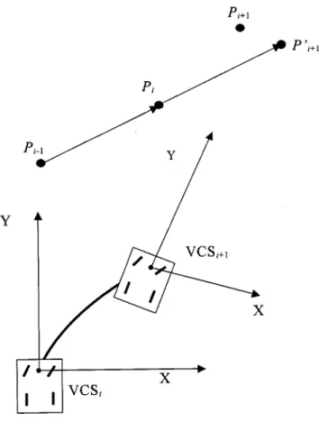
More specifically, as shown in Fig. 2, let denote the person position and denote the vehicle coordinate system at the beginning of cycle during navigation. Assume that, at the be-ginning of cycle , the and coordinates of the person posi-tion at with respect to have been found. We use the ALV control information to estimate the translation from to , which is then used to compute the and coordinates of the person position at with respect to . Also, assume that, at the beginning of cycle , the and
Fig. 2. Illustration of the positionP ; P ; P , andP .
coordinates of the person position at with respect to have been found. Again, the ALV control information is used to estimate the translation from to , which is then used to compute the and coordinates of the person positions
at and with respect to .
After and are found in cycle , we then detect as follows. We first predict the person position, called , at the beginning of cycle using and . The prediction process is illustrated in Fig. 2, where it is assumed that the trans-lation from to is identical to that from to . The predicted person position is reasonable because in the short du-ration between two cycles the person may be assumed to move straightforward with a constant speed in general. Since the and coordinates of the person positions at and with respect to have been computed previously, the and coor-dinates of the person position at with respect to
can be solved accordingly. Then, the predicted person position is used to detect the real person position . The way is to find the object closest to and take it as the detected person located at .
The details of the above process are described in the fol-lowing. We first state the estimation process of the translation from to in Section II-A. Then, in Section II-B, the derivation process of the coordinates of the person position at and with respect to is introduced, followed by a description of the prediction process of the person position at . Finally, the detection process of the person position at
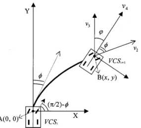
Fig. 3. Analysis of the pathS, through which the vehicle navigates from locationA to B by turning an angle of .
A. Estimation of Translation from to
The translation from to is estimated using the ALV control information, namely, the speed and the turn angle of the ALV, and the time interval between two sampling instants. These values can be obtained from the feedback information of the ALV and then used to estimate the kinematic trajectory of the ALV from to . Accordingly, the translation and the rotation of the two VCSs can be obtained. The details are as follows.
Consider the simple kinematic model for an automobile with front and rear tires [12], as shown in Fig. 3. The rear tires are aligned with the car body sides while the front tires are allowed to spin about the vertical axes. Besides, the center position between the two front wheels is treated as the origin of the VCS. As shown in Fig. 3, the vehicle moves a distance from location to lo-cation by turning an angle of , where and represent the origin of the and that of the , respectively. We as-sume that the vehicle speed and the navigation time interval of the vehicle are both known in advance. Hence, the navigation distance is a constant and can be computed by .
The translation specified by the values and in the is acquired by the following equations [5]:
(1) where
rotation radius;
distance between the front wheels and the rear wheels; , corresponding angle and the secant line of ,
respec-tively;
turning angle of the front wheels.
Fig. 4. Illustration of and '.
According to (1), the translation ( ) from to is computed to be as follows:
(2)
(3) Next, we state the derivation process of the rotation angle, denoted as , from to . Since the direction vector of the vehicle head in the VCS is that of the axis of the VCS, the angle can be obtained by calculating the angle between the direction vector of the vehicle head at the position and that at the position , as shown in Fig. 3. Thus, the direction vector of the vehicle head at the position with respect to can be written as
(4) In addition, as shown in Fig. 4, the direction vector of the vehicle head at the position with respect to can be derived from the direction vector of the front wheels of the vehicle at the position in the following way. First, since the vector is the tangent of the trajectory of the ALV, it can be obtained to be as follows [14]:
(5) Then, because the angle between vectors and is the turn angle of the vehicle, the vector can be calculated to be as follows:
Fig. 5. Illustration of the coordinates ofP ,P , and P with respect to
V CS and V CS .
Hence, the angle between the two direction vectors and can be calculated according to the following equation:
(7) By substituting (4) and (6) into (7), the angle can be derived to be as shown by(8), at the bottom of the page.
B. Prediction of Person Position at
In this section, we describe the derivation process of the co-ordinates of the person position at and with respect to , followed by a description of the prediction process of the person position at . As shown in Fig. 5, let and denote the coordinates of the person position at with respect to . Similarly, let and represent the coordi-nates of the person position at with respect to . Assume that the coordinates ( ) and ( ) with respect to have been obtained. The translation ( ) and the rota-tion angle from to , obtained in the previous section, can be used to calculate the coordinates ( ) and ( ) of the person position at and with
re-spect to , respectively, by the following equations:
(9)
(10) In (9), the center of is translated to that of
so that the coordinates of with respect to have to decrease the translation ( ). In addition, the direction of is rotated to be the same as that of according to the angle . Hence, the coordinates ( , ) of with respect to can be obtained in (9). In the mean time, the coordinates ( ) of with respect to is obtained in (10).
Since we assume that the translation from to is iden-tical to that from to , the coordinates ( ) of the predicted person position at with respect to can be calculated to be as follows:
(11) (12)
C. Detection of Person Position at
When the predicted person position is obtained, the person position can be detected, as mentioned previously, to be the object closest to . However, each candidate ob-ject is necessarily just a point in shape; it is a group of points composing a baseline segment. Therefore, a more sophisticated method is adopted in this study, based on the use of the mean and the variance of the detected baselines. The mean of the baseline of an object represents the position of the object and its value is obtained by the following equation:
(13) where is the number of the points that compose a baseline of an object and represents the coordinates of those points from the top view of the VCS. The calculated mean of the object is used to compute the Euclidean distance to the po-sition . Since the coordinates and of the position
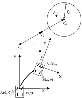
Fig. 6. Illustration of the detected person positionP and the distance threshold valueT .
have been obtained, the Euclidean distance between the mean and the position can be obtained by the following equation:
(14) The obtained distance is taken as one of features to detect the person position . As shown in Fig. 6, if an object is the person that we want to detect, its distance will be smaller than a given threshold value . On the other hand, the variance of the points that compose a baseline of an object is taken as another feature and its value can be obtained by the following equation:
(15) Since the length of the baseline of a person is smaller than that of a wall and an obstacle in general, the variance of the person will be smaller than a given threshold value . Hence, the proposed method for detecting the position includes two steps and is described in the following. In the first step, we check whether the variance and the distance of an object are smaller than the thresholds value and , respectively. The conditions may be written as follows:
(16) and
(17) When all detected objects are tested using the two conditions (16) and (17), three situations might happen. The first situation is that no object satisfies both of the two conditions. It means that the ALV misses the followed person. In this case, the ALV is stopped. The second situation is that just one object satisfies
both of the two conditions. The object is then taken as the fol-lowed person at . The last situation is that more than one object satisfies both of the two conditions. Then, the object with the smallest distance is chosen to be the person to follow. That is, in the second step, when the distance between and an object is the smallest, the object is regarded as the followed person at and the remaining objects are re-garded as obstacles. If the object with the smallest distance is an obstacle instead of the followed person, the followed person cannot be detected around the area that is predicted using the proposed method in Section II-B. Hence, the ALV will stop in the next cycle and restart to detect an moving object as the fol-lowed person.
III. PROPOSEDCOLLISION-FREEPATHGENERATIONMETHOD FOROBSTACLEAVOIDANCE INPERSONFOLLOWING
In this section, the guidance method for obstacle avoidance in person following is proposed. The goal of this method is to generate a collision-free path that passes through the location of the followed person and the middle point between the two front wheels of the vehicle without hitting the obstacles. This goal is achieved using the proposed pattern generation method and the path generation method described in the following.
In the proposed path generation method, the decision boundary of the quadratic classifier is treated as the generated collision-free path. When the quadratic classifier is applied, there need two classes of patterns for use as the input. On the other hand, the proposed pattern generation method provides a systematic way to categorize all patterns into two groups and . These patterns include the baseline of obstacles, two sides of the vehicle body, and two series of artificial patterns generated on the left-hand and the right-hand sides of the person location. The pattern generation method is proposed in Section III-A. In Section III-B, the formula of the quadratic classifier is described.
A. Pattern Generation for Quadratic Classifier Design
In this section, a pattern generation method is proposed to categorize all patterns into two groups and , which include two kinds of obstacle patterns and , two kinds of vehicle patterns and , and two kinds of person patterns and in the VCS. The details of the processing step are described in the following.
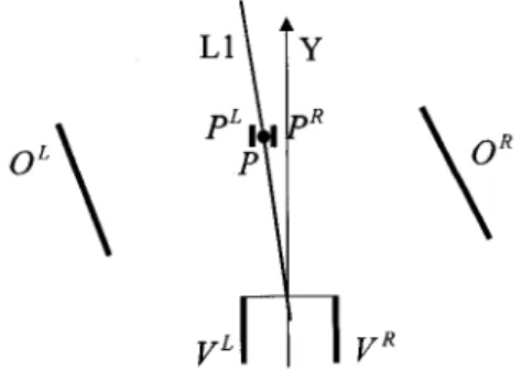
In this study, all detected objects except the followed person are treated as obstacles. The baseline of an obstacle is catego-rized into one of two sets and according to a derived reference line in the VCS. As shown in Fig. 7, the reference line passes through the person’s position and the origin of the VCS. With the coordinates and of the person’s position obtained in Section II-C, the formula of the reference line can be derived to be as follows:
(18) If a point ( ) is located on the left-hand side of the line , the value of with respect to ( ) is smaller than zero. Hence, if the mean of the baseline of an obstacle is on the left-hand side of the reference line , i.e., if , the baseline of
Fig. 7. Two kinds of obstaclesO and O , two kinds of vehicle patterns V andV , and two kinds of person patterns P and P in the VCS.
the obstacle is assigned to a component of the set . Here, the mean position of the baseline points of an obstacle represents the position of the obstacle. On the contrary, if the mean position of the baseline points of the obstacle is on the right-hand side of , i.e., if , the baseline of the obstacle is assigned to a component of the set . That is, the baseline of an obstacle can be categorized by the following rule:
assign to if
if (19)
where represents the mean of the baseline of the ob-stacle.
In the following, we state the proposed method for generating two sets and of patterns to represent the left-hand side and the right-hand side of the person position, respectively. The scheme makes the decision boundary pass through the person’s position so that the collision-free path can be used as a naviga-tion path in person following. As shown in Fig. 7, the person’s position is taken to be the mean of the baseline of the person. Each of the two generated pattern sets and are designed to be composed of a series of points that are located on the left-hand or the right-hand sides, respectively, of the position . The distance between the pattern set and the position , and the pattern set and the position are both 30 cm. The length of or is also 30 cm.
Besides the pattern sets and , as shown in Fig. 7, we regard the points of the projection of the left-hand and the right-hand sides of the vehicle body in the – plane of the VCS as two sets of patterns and , respectively. This scheme makes the collision-free path to go through the origin of the VCS, i.e., to go through the middle point between the two front wheels of the vehicle.
Now, we describe how to associate separately each of the pat-tern sets and with the person pattern sets and , and the obstacle pattern sets and for finding the colli-sion-free path. The scheme for categorizing the six kinds of
pat-terns , and into two groups and
is based on the following rule:
(20) and
(21) More specifically, the left vehicle pattern set is associated with the left person pattern set and the obstacle pattern set . On the other hand, the right vehicle pattern set is
as-Fig. 8. A two-dimensional decision boundary,h(X), passing through the origin of the VCS (i.e., through the middle point of the two vehicle wheels) and the person’s location, is found by the quadratic classifier.
sociated with the right person pattern set and the obstacle pattern set . In this way, the two groups and are obtained, which are then used as the input to the classification designed by the way described in the next section.
B. Quadratic Classifier for Path Generation
From the result of the pattern generation processes to be described in Sections III-A, we can obtain two pattern groups and , each of which includes patterns representing obstacles, corridor walls on one side of the vehicle, the two sides of the vehicle body, and that of the person. In this study, the quadratic classifier is used to generate a quadratic decision boundary between and . The decision boundary is taken as a collision-free path that the ALV follows to achieve safe navigation in person following. Since the generated path is limited to go through the middle point between the two front wheels of the vehicle (i.e., through the origin of the VCS) in this study, as shown in Fig. 8, the decision boundary will approach the person’s location without hitting the obstacles. The vehicle can thus safely follow the person by navigation along the derived collision-free path . The details for generating the decision boundary are described as follows.
As shown in Fig. 8, let and be two groups of pat-terns representing obstacles, and be those representing the followed person, and and be those representing the vehicle body sides. In this study, and belong to the group , and and belong to the group . Each pat-tern in the patpat-tern group consists of and values in the VCS. We denote the coordinates of the th pattern in as
and those of the th pattern in as .
According to the theory of pattern recognition [13], we can find a quadratic decision boundary between the patterns of two classes to form a quadratic classifier. A general representation of the quadratic classifier is written as follows:
(22) where is a constant, and the vector specifies a pattern of or . If , it means that belongs to ; if , it means that belongs to .
Since the collision-free path is limited to go through the middle point between the two front wheels of the vehicle, i.e., the origin of the VCS, the value of in (22) can be set as zero. The formula of the decision boundary in (22) can be represented as follows [5]:
(23) where
and
We can use the technique for designing a linear classifier to find the coefficients ( ) as follows.
Let . The values of
matrix come from those of the patterns of and . Matrix for and will be denoted as and , respectively. Substitute the values of and in matrix by those of the th point of and , and denote the resulting matrix by . Similarly, substitute the values of and in matrix by those of the th point of and
, and denote the resulting matrix by .
Accordingly, the nonlinear solutions of the coefficients for the quadratic classifier whose input design patterns come from the points of and are equal to the linear solutions of the coeffi-cients for the linear classifier whose input design patterns come from the points of and . Therefore, the five coefficients in (23) can be solved [5] and the result is represented as follows: (24) where and and and are the means and variances of and , respectively, and are computed as follows:
(25) and and are the numbers of points of and , respectively.
Fig. 9. The vehicle is guided automatically to follow a person who walks in front of the vehicle.
Fig. 10. The prototype ALV used in this study.
By substituting (25) into (24), the five coefficients of in (23) are obtained so that the quadratic decision boundary is generated. The ALV can navigate along the derived collision-free path to achieve safe navigation by person following.
IV. EXPERIMENTALRESULTS
The proposed method has been implemented on a real ALV to follow a walking person, as shown in Fig. 9. The ALV, as shown in Fig. 10, is four-wheeled with two motors controlling the front and rear wheels, respectively. The width and the length of the ALV are 40 and 120 cm, respectively. The length between the front wheels and the rear wheels of the ALV is 82 cm. The struc-ture of the vehicle system is introduced in detail in [5]. In our experiments, images taken by the image frame grabber are 512 486 pixels in resolution. The velocity of the vehicle is 31.75 cm/s, which is equivalent to 1.14 km/h. This velocity is accept-able in many applications in indoor environments. In addition, the vehicle modifies the turning angle every 1.5 s. Because the speed of the person has to be smaller than that of the ALV, the maximum speed of the person is about 31.75 cm/s. In addition, in the experiment, one situation that the followed person does
Fig. 11. An example of baseline detection results.
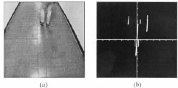
Fig. 12. An experimental result of the generated collision-free path. (a) Detection result of walls and the followed person. (b) Top view of obstacles and a generated path.
Fig. 13. Another experimental result of generated collision-free path. (a) Detection result of a wall, the followed person, and an obstacle on the ground of the corridor. (b) Top view of obstacles and a generated path.
not appear in the captured image may cause the wrong com-mand in the navigation. This case is discussed and solved using a method proposed in [14].
An example of the captured image is shown in Fig. 11, in which the detected baselines are drawn as white lines. Figs. 12–16 show some experimental results in a real indoor corridor environment. Figs. 12(a) and 13(a) are real images captured by a wide-angle camera. The white lines in these figures are composed of the patterns of the detected obstacles. Figs. 12(b) and 13(b) show the – plane of the VCS. All the patterns representing the obstacles, the followed person, and the vehicle in the VCS are shown as white points. The
Fig. 14. An experimental result shows that the distance between the followed person and a wall is smaller than the width of the vehicle body. (a) Detection result of walls and the followed person. (b) Top view of obstacles and a generated path.
generated collision-free path that goes through the origin of the VCS and the person position is also shown in Figs. 12(b) and 13(b). According to the generated path, a modification of the turning angle can be computed using the path following method described in [5].
As shown in Fig. 12, two walls and the followed person are detected and the collision-free path is correctly generated. As shown in Fig. 13, the generated collision-free path is between the wall and the obstacle. If the distance between the followed person and obstacles is smaller than the width of the vehicle body, the person patterns are not treated as input to generate a collision-free path. As shown in Fig. 14, since the distance be-tween the followed person and the wall is smaller than the width of the vehicle body, the generated collision-free path does not pass through the location of the followed person so that the ve-hicle will avoid collision with the wall when it navigates along the path. An experimental result showing the ALV successively following a walking person without collision in the corridor is shown in Fig. 15. The sequence of the captured images is shown in Fig. 15(a). The corresponding – planes of the VCS with re-spect to the captured images are illustrated in Fig. 15(b). Fig. 16 includes another sequence of experimental images showing the ALV following a person in the corridor.
V. CONCLUSIONS
In this paper, an obstacle avoidance method for use in person following for vision-based ALV guidance has been proposed. The approach is based on the use of vehicle location estima-tion and the quadratic pattern classifier, and enables the ALV to follow safely a walking person through corridor environments with obstacles by navigating along a derived collision-free path. In this approach, the estimated translation of the vehicle location from the previous sampling intant to the current one is used to predict the person location at the current sampling instant. The object closest to the predicted person location is regarded as the followed person and the remaining objects are regarded as stacles. After obtaining the person’s location from extracted ob-jects by the proposed person detection method, a collision-free path can be generated by a path generation method. The navi-gation path is generated from a quadratic classifier that uses the vehicle and all of the objects in the image as input patterns. All patterns are categorized into two classes to be the input to the
Fig. 15. A sequence of experimental images in the corridor of a real indoor environment. (a) Captured images. (b) Top views of obstacles and generated collision-free paths with respect to the captured images.
Fig. 16. A sequence of experimental images in the corridor of a real indoor environment.
classifier using a pattern generation method. The collision-free navigation path is designed for ALV guidance in such a way that the ALV not only can keep following the person but also can avoid collision with nearby obstacles. This approach has been implemented on a real ALV. Successful and safe navigation ses-sions confirm the feasibility of the approach.
REFERENCES
[1] A. Ohya, A. Kosaka, and A. Kak, “Vision-based navigation of mobile robot with obstacle avoidance by single camera vision and ultrasonic sensing,” in Proc. IEEE/RSJ Int. Conf. Intelligent Robot and Systems, vol. 2, Grenoble, France, Sept. 1997, pp. 704–711.
[2] L. M. Lorigo, R. A. Brooks, and W. E. L. Grimsou, “Visually-guided obstacle avoidance in unstructured environments,” in Proc. IEEE/RSJ
Int. Conf. Intelligent Robot and Systems, vol. 1, Grenoble, France, Sept.
1997, pp. 373–379.
[3] Y. G. Yang and G. K. Lee, “Path planning using an adaptive-network-based fuzzy classifier algorithm,” in Proc. 13th Int. Conf. Computers
and Their Applications, Honolulu, HI, Mar. 1998, pp. 326–329.
[4] R. Biewald, “Real-time navigation and obstacle avoidance for nonholo-nomic mobile robots using a human-like conception and neural parallel computing,” in Proc. Int. Workshop Parallel Processing by Cellular
Au-tomata and Array, Berlin, Germany, Sept. 1996, pp. 232–240.
[5] C. H. Ku and W. H. Tsai, “Obstacle avoidance for autonomous land vehicle navigation in indoor environments by quadratic classifier,” IEEE
Trans. Syst., Man, Cybern. B, vol. 29, pp. 416–426, June 1999.
[6] O. Masoud and N. P. Papanikolopoulos, “Robust pedestrian tracking using a model-based approach,” in Proc. IEEE Conf. Intelligent
Trans-portation Systems, Boston, MA, Nov. 9–12, 1997, pp. 338–343.
[7] J. Denzler and H. Niemann, “Real-time pedestrian tracking in natural scenes,” in Proc. 7th Int. Conf. Computer Analysis of Images and
Pat-terns, Berlin, Germany, Sept. 10–12, 1997, pp. 42–49.
[8] L. Trassoudaine, S. Jouannin, J. Alizon, and J. Gallice, “Tracking sys-tems for intelligent road vehicles,” Int. J. Syst. Sci., vol. 27, no. 8, pp. 731–743, 1996.
[9] V. F. Munoz and A. Ollero, “Smooth trajectory planning method for mobile robots,” in Proc. Conf. Computational Engineering in Systems
Applications, Lille, France, July 9–12, 1996, pp. 700–705.
[10] Z. Shiller and W. Serate, “Trajectory planning of tracked vehicles,”
Trans. ASME, J. Dynam. Syst., Meas. Control, vol. 117, no. 4, pp.
[11] C. H. Ku and W. H. Tsai, “Smooth vision-based autonomous land ve-hicle navigation in indoor environments by person following using se-quential pattern recognition,” J. Robot. Syst., vol. 16, no. 5, pp. 249–262, May 1999.
[12] R. M. Murray and S. S. Sastry, “Nonholonomic motion planning: Steering using sinusoids,” IEEE Trans. Automat. Contr., vol. 38, pp. 700–716, May 1993.
[13] K. Fukunaga, Introduction to Statistical Pattern Recognition, 2nd ed. San Diego, CA: Academic, 1990.
[14] C. H. Ku and W. H. Tsai, “Robust trajectory planning in person fol-lowing for vision-based autonomous land vehicle guidance by visual field model and visual contact constraints,” in Proc. Conf. Computer
Vision, Graphics, and Image Processing, Taipei, Taiwan, R.O.C., Aug.
1999, pp. 771–780.
Ching-Heng Ku was born in Taipei, Taiwan, R.O.C.,
in 1970. He received the B.S. degree from Tamkang University, Taipei, Taiwan, R.O.C., and the Ph.D. de-gree from National Chiao Tung University, Hsinchu, Taiwan, R.O.C., in 1993 and 1999, respectively.
He is currently with the Division of System and Networking, National Center for High-Performance Computing, National Science Council, Hsinchu, Taiwan, R.O.C. His major research interests include computer vision, image processing, pattern recogni-tion, and autonomous land vehicle navigation.
Wen-Hsiang Tsai (S’78–M’79–SM’91) was born
in Tainan, Taiwan, R.O.C., in 1951. He received the B.S. degree in electrical engineering from National Taiwan University, Taipei, Taiwan, R.O.C., the M.S. degree in electrical engineering (with a major in computer science) from Brown University, Providence, RI, and the Ph.D. degree in electrical engineering (with a major in computer engineering) from Purdue University, West Lafayette, IN, in 1973, 1977, and 1979, respectively.
In November 1979, he joined the faculty of Na-tional Chiao Tung University, Hsinchu, Taiwan, R.O.C., where he is currently a Professor in the Department of Computer and Information Science and the Dean of Academic Affairs. He is also the Editor-in-Chief of the Journal of
Informa-tion Science and Engineering, Editor of the Journal of Chinese Engineers, and
the Chairman of the Chinese Image Processing and Pattern Recognition Society of Taiwan. His major research interests include image processing, pattern recog-nition, computer vision, neural networks, and Chinese information processing. He has authored about 240 published academic papers, including 103 journal papers and 137 conference papers. He has supervised the thesis studies of 24 Ph.D. students and 91 M.S. students.
Dr. Tsai is a member of the Chinese Image Processing and Pattern Recogni-tion Society, the Medical Engineering Society of the Republic of China, and the International Chinese Computer Society.