國立交通大學
電子工程學系 電子研究所
碩 士 論 文
考量島間傳遞延遲的分散式暫存器檔案架構之
效能考量架構合成
Performance-Driven Architectural Synthesis for Distributed
Register-File Microarchitecture with Inter-Island Delay
研 究 生:許婉玲
指導教授:周景揚 教授
黃俊達 教授
考量島間傳遞延遲的分散式暫存器檔案架構
之效能考量架構合成
Performance-Driven Architectural Synthesis for
Distributed Register-File Microarchitecture with
Inter-Island Delay
研究生:許婉玲 Student: Wan-Ling Hsu
指導教授:周景揚 教授 Advisor: Jing-Yang Jou
黃俊達 教授 Juinn-Dar Huang
國立交通大學
電子工程學系 電子研究所
碩士論文
A Thesis
Submitted to Department of Electronics Engineering & Institute of Electronics College of Electrical & Computer Engineering
National Chiao Tung University in Partial Fulfillment of the Requirements
for the Degree of Master
in
Electronics Engineering & Institute of Electronics September 2009
Hsinchu, Taiwan, Republic of China
考量島間傳遞延遲的分散式暫存器檔案架構
之效能考量架構合成
研究生:許婉玲 指導教授:周景揚 教授
黃俊達 教授
國立交通大學
電子工程學系 電子研究所碩士班
摘 要
進入深次微米時代,過長的連線導致過大的延遲,使得系統的效能難以繼續提高。 在過去數種分散式暫存器架構已被提出,企圖使用較短的區域連線進行大部分的資料傳 輸,以解決延遲的問題。在本篇論文中,我們提出一種分散式架構,稱之為考慮島間傳 遞延遲的分散式暫存器檔案的架構。在這個架構上,提出一個合成流程使得整體效能盡 可能達到最好。首先,分配運算子到島上得到一個初步的結果;接著,利用反覆增加效 能的方法,嘗試得到更佳的結果。由實驗結果得知,與前作相比,我們可以將效能增加 平均達到百分之二十九點二。Performance-Driven Architectural Synthesis for
Distributed Register-File Microarchitecture with Inter-Island
Delay
Student: Wan-Ling Hsu Advisor: Prof. Jing-Yang Jou
Prof. Juinn-Dar Huang
Department of Electronics Engineering & Institute of Electronics
National Chiao Tung University
Abstract
In deep-submicron era, wire delay is becoming the bottleneck while pursuing high system clock speed. Several distributed register (DR) architectures are proposed to cope with this problem by keeping most wires local. A distributed register-file microarchitecture with inter-island delay (DRFM-IID), proposed in this thesis, is one of the DR-based architectures. We also provide a performance-driven architectural synthesis framework targeting DRFM-IID. First, Island Assignment is performed to bind operations into islands. Then, a procedure performing Iterative Latency Minimization is utilized further improve outcomes. The experimental results indicate that the latency can be reduced by 17.6% ~ 29.2% on average, as compared to the prior one.
誌 謝
首先,我要感謝我的指導教授-周景揚教授與黃俊達博士,在碩士兩年當中給我 的支持和鼓勵,讓我能有良好的研究環境,在自由的學習風氣之下,培養出獨立研究的 能力,又能隨時給予寶貴的意見及指導,對老師們的感激之情,並非以簡短的文句可以 表達。 當然也要感謝養育我長大的父母對我的栽培,沒有他們,就沒有今日的我。接著 要感謝的是所有來參與口試的所有教授們,陳宏明教授和張世杰教授,百忙當中抽空前 來指導我,讓我受益匪淺,也讓我得到了寶貴的經驗,謝謝你們。 我也要感謝實驗室的同學、學長姐和學弟妹,跟大家一起修課、做實驗和討論及 分析研究成果更是我人生旅途中一段最值得珍惜的回憶,希望未來在讀書或工作還有機 會一起努力。 希望這篇論文能對人類社會有小小的貢獻,如此一來再辛苦也就值得了,再次謝謝 大家的幫忙。Contents
Abstract (Chinese) ...i
Abstract (English)...ii Acknowledgement ...iii Contents ...iv List of Tables ... v List of Figures...vi Chapter 1 Introduction... 1
Chapter 2 Related Works ... 5
2.1 Distributed Register Architecture ... 5
2.2 Distributed Register-File Microarchitecture... 7
Chapter 3 Distributed Register-File Microarchitecture With Inter-Island Delay ... 9
Chapter 4 Motivational Examples ... 10
4.1 Effects of IITs ... 10
4.2 Effects of Criticality ... 11
4.3 Effects of Islands Utilizations... 13
Chapter 5 Proposed Algorithm ... 15
5.1 Overview ... 15
5.2 Island Assignment ... 17
5.3 Iterative Latency Minimization ... 21
5.3.1 IIT Refinement ... 22
5.3.2 Conveyer Insertion ... 26
Chapter 6 Experimental Results ...27
Chapter 7 Conclusion ...33
List of Tables
Table 1 The utilizations of islands ... 14
Table 2 The utilizations of islands... 14
Table 3 The corresponding island information... 24
Table 4 Gain and partial sum of gain in one iteration ... 25
Table 5 The basic information of benchmarks ... 30
Table 6 Experimental results of the latency in Configuration 1. ... 31
Table 7 Experimental results of IITs and IICs in Configuration 1. ... 31
Table 8 Experimental results of the latency in Configuration 2 ... 32
List of Figures
Fig. 1 : Delay versus feature size... 1
Fig. 2 : The island architecture of DRFM ... 2
Fig. 3 : The island architecture of DRFM-IID... 3
Fig. 4 : Centralized register architecture ... 5
Fig. 5 : Distributed register architecture... 6
Fig. 6 : A scheduled and bound DFG ... 7
Fig. 7(a): A DFG on DRFM ... 9
Fig. 7(b): A DFG on DRFM-IID ... 9
Fig. 8(a) : A scheduled and bound DFG ... 10
Fig. 8(b) : A scheduled and bound DFG after conveyer insertion... 10
Fig. 8(c) A scheduled and bound DFG ... 10
Fig. 8(d) : A scheduled and bound DFG after conveyer insertion... 10
Fig. 9 : A scheduled DFG ... 11
Fig. 10(a) : A scheduled and bound DFG ... 12
Fig. 10(b) : A scheduled and bound DFG after conveyer insertion... 12
Fig. 10(c) : A scheduled and bound DFG ... 12
Fig. 10(d) : A scheduled and bound DFG after conveyer insertion... 12
Fig. 11(a) : A scheduled and bound DFG ... 14
Fig. 11 (b) : A scheduled and bound DFG after conveyer insertion ... 14
Fig. 11 (c) : A scheduled and bound DFG ... 14
Fig. 11 (d) : A scheduled and bound DFG after conveyer insertion ... 14
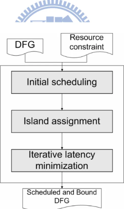
Fig. 12 : The overall flow of the proposed algorithm... 15
Fig. 13(a) : A scheduled and bound DFG, #islands = 2 ... 17
Fig. 14 : A compatibility graph with pseudo source and sink ... 18
Fig. 15 : An example of edge weight calculation ... 19
Fig. 16 : An edge-weighted compatibility graph ... 19
Fig. 17 : The scheduled and binding result... 20
Fig. 18 : Two key steps of Iterative Latency Minimization... 21
Fig. 19 : A FSPS example... 22
Fig. 20 : An example of swap gain calculation ... 23
Fig. 21(a) : The DFG at the beginning of the iteration... 24
Fig. 21 (b) : The DFG at the end of the iteration... 24
Fig. 22 : An example of Conveyer Insertion ... 26
Chapter 1
Introduction
As advancing into the deep-submicron (DSM) era, interconnects have become a crucial issue for electronic circuit and system designs. In particular, global interconnections extremely affect the performance, area and power dissipation of modern systems [1]–[3].
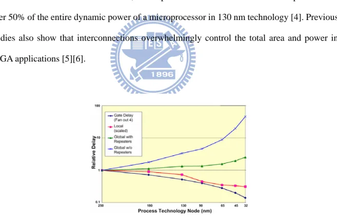
Fig. 1 shows that the interconnect delay, especially the global one, does not decrease well when the feature size decreases. In addition, it is reported that interconnections are responsible for over 50% of the entire dynamic power of a microprocessor in 130 nm technology [4]. Previous studies also show that interconnections overwhelmingly control the total area and power in FPGA applications [5][6].
Fig. 1 : Delay versus feature size
Several approaches have been proposed to deal with the critical issue arisen from long interconnects. Globally-asynchronous locally-synchronous (GALS) designs adopt handshaking protocols for communication between different modules over long interconnects [7]. In a
synchronous latency-insensitive system (LIS), special pipelining elements, named relay stations, are inserted to break a long interconnect into shorter wire segments in order to sustain high operating clock frequency [8]. Moreover, several types of distributed register (DR) architectures, in which the entire system is divided into several logic clusters, are also broadly studied [9]–[20]. In general, all DR-based architectures try to keep most interconnects local within a cluster and thus minimize the number of required inter-cluster long interconnects for better performance and smaller area.
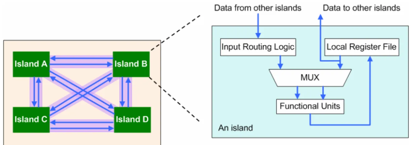
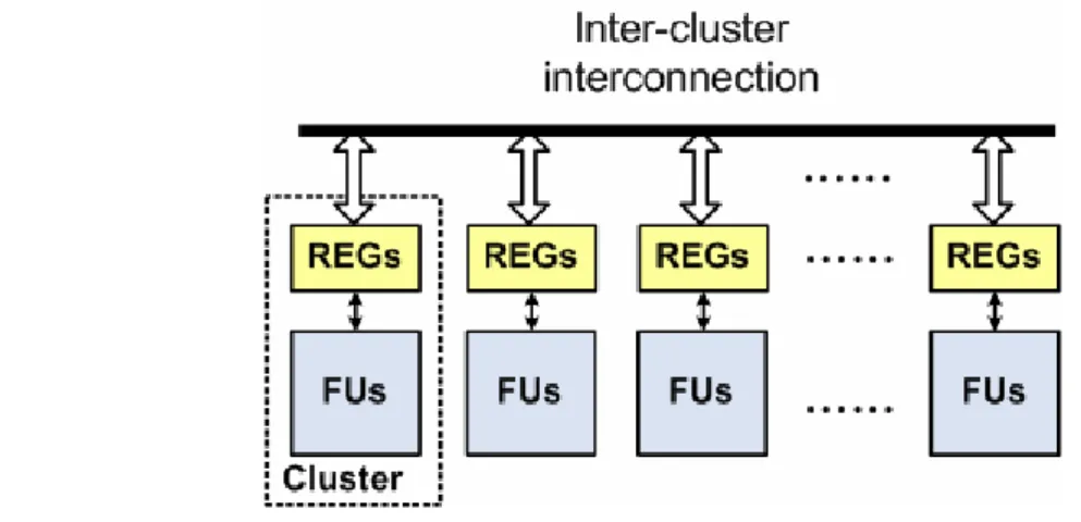
Distributed register-file microarchitecture (DRFM) is one of the DR-based architectures and is recently proposed in [9]. As shown in Fig. 2, DRFM consists of multiple islands and each of them has its own register file, functional units (FUs), and data-routing logic. Moreover, DRFM is adequate for platforms with a rich set of distributed memory blocks, e.g., modern FPGAs [21]–[22]. It is proven in [9] that the total number of inter-island connections (IICs) is highly correlated with the area and performance of synthesized designs. Therefore, the number of IICs is a good evaluation metric for quality of result (QoR) on DRFM. Accordingly, a resource constraint binding algorithm was also proposed in [9], and its target is to minimize the number of IICs.
Fig. 2 : The island architecture of DRFM
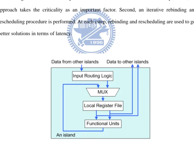
model appears oversimplified. In order to incorporate the IIT delay, we propose a new architecture named distributed register-file microarchitecture with inter-island delay (DRFM-IID), which considers unit inter-cluster delay and makes a move toward reality. Of course, the corresponding synthesis task is inherently more complicated. As shown in Fig. 3, DRFM-IID consists of multiple islands, each island having a local register file, functional units (FUs), data-routing logic. In DRFM-IID, data from other islands should be stored in the local register file first and then go to local functional unit at the next control step (cstep). Therefore, the system latency would increase due to the IIT delay. In this thesis, we propose a resource constraint binding algorithm targeting DRFM-IID for minimizing system latency. Given a data
flow graph (DFG) and a resource constraint (i.e., number of available islands). First, we realize
that binding nodes on the critical path to the same island could reduce the latency. Hence, our approach takes the criticality as an important factor. Second, an iterative rebinding and rescheduling procedure is performed. At each cstep, rebinding and rescheduling are used to get better solutions in terms of latency.
Fig. 3 : The island architecture of DRFM-IID
The rest of this thesis is organized as follows. The related works are discussed in Chapter 2. Chapter 3 and Chapter 4 present the details of DRFM-IID synthesis and motivational examples.
Chapter 5 presents the details of our proposed algorithm for DRFM-IID synthesis. The experimental results and analyses are given in Chapter 6, followed by the conclusions in Chapter 7.
Chapter 2
Related Works
2.1 Distributed Register Architecture
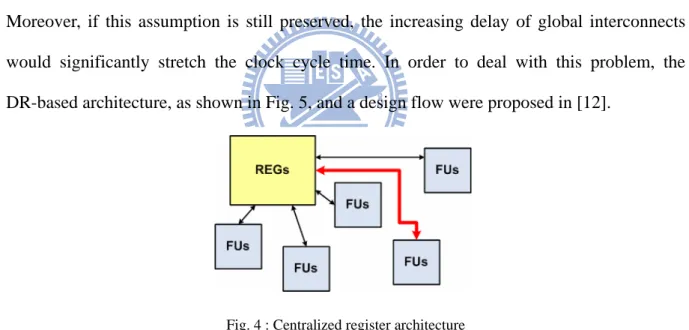
Conventionally, centralized register (CR) architectures are usually presumed in high level synthesis. In a CR-based architecture, as shown in Fig. 4, there exists a large aggregate register file shared by all FUs and an FU is expected to access any register within one clock cycle. Moreover, if this assumption is still preserved, the increasing delay of global interconnects would significantly stretch the clock cycle time. In order to deal with this problem, the DR-based architecture, as shown in Fig. 5, and a design flow were proposed in [12].
Fig. 5 : Distributed register architecture
In a DR-based architecture, the whole system is partitioned into a set of clusters and each cluster contains its own local register file and FUs. As a result, most register accesses are kept within a cluster while only few accesses require long inter-cluster communication.
2.2 Distributed Register-File Microarchitecture
The island structure of DRFM is shown in Fig. 2. An island is composed of a local register file , FUs, and input routing logic. The local register file is used to supply data for internal FUs and external FUs in other islands, and store computation results produced by internal FUs. DRFM allows use of the platform-featured on-chip memory or register-file IP blocks to implement its local register files, and the results in substantial saving of multiplexing logic and global interconnects [9].
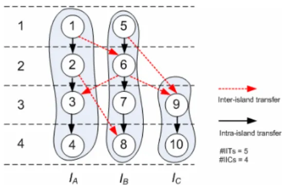
Because the correlation between the number of IICs in DRFM and the area and performance of designs is high, the number of IICs in DRFM is a good measure of QoR in early design phases [9]. As shown in Fig. 6, the number of IICs can be calculated after scheduling and binding. The operations in the same shaded region are bound to the same island, and the ones in the same row are scheduled at the same cstep. Then, data transfers whose start node and end node are in different islands become inter-island transfers (IITs). In the example of Fig. 6, IIT1,6
and IIT2,8 are IITs from island A to island B, IIT6,3 is an IIT from island B to island A, and IIT5,9
and IIT6,9 are IITs from island B to island C. Since DRFM assumes point-to-point IICs, two IITs
can share an IIC if and only if they are produced from a common island and consumed in another common island at different csteps [9]. In the example of Fig. 6, IIT1,6 and IIT2,8 can
share an IIC between island A and island B. On the contrary, IIT5,9 and IIT6,9 must use two
different IICs between island B and island C because they are consumed at the same cstep.
An approach for IIC minimization in DRFM was proposed in [9]. For simplicity, it proposes the following two assumptions. First, every operation can be executed in any island in one cstep and produces exactly one result. Second, a local register file has only one write port for the writeback of FUs on the same island. We also take these two assumptions in our work. In DRFM, IIT delay is ignored. To be more practical, IIT delay should be considered. Therefore, we propose DRFM-IID to solve this problem.
Chapter 3
DRFM-IID
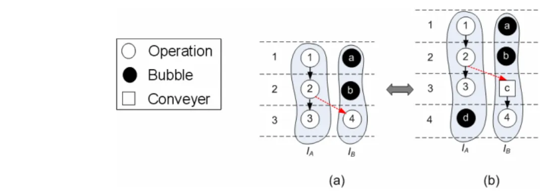
As mentioned above, DRFM ignores IIT delay. In this thesis, we propose a new architecture, named DRFM-IID to overcome this issue. In DRFM-IID, we assume every IIT takes one cstep delay. Data from other islands should be stored in the local register file at first and then go to the internal FUs at the next cstep. After calculation, computation results are stored in the local register file. Since the architecture is modified, the DFG and scheduling have to be altered accordingly. A special node, named conveyer, which represents the endpoint of an inter-island data transfer, is added on the IIT destination island. As shown in Fig. 7(a), there exists an IIT2,4 in the DFG on DRFM. For IIT2,4, v2 is at cstep2 and v4 is at cstep3. After
conveyer insertion, the corresponding DFG is shown in Fig. 7(b). We add a conveyer C into the destination island, island B, at cstep3, and move v4 to cstep4. As a result, the latency increases
from 3 csteps to 4 csteps. Since inserting conveyers can increase the latency, the synthesis task must make a good care of it. In this thesis, we propose an algorithm to minimize the latency by rescheduling and rebinding. The proposed algorithm is introduced in Chapter 4.
Chapter 4
Motivational Examples
4.1 Effects of IITs
The number of IITs may affect the latency because extra conveyers may make critical paths even longer. An example is shown in Fig. 8. Two binding solutions are depicted in Fig. 8(a) and Fig. 8(c). In Fig. 8(a), the number of IITs is 2. After inserting conveyers, the latency increases from 3 csteps to 5 csteps, as shown in Fig. 8(b). In Fig. 8(c), the number of IITs is 1. After inserting conveyers, the latency remains 3 cstps, as shown in Fig. 8(d).
Fig. 8(a) : A scheduled and bound DFG
(b) : A scheduled and bound DFG after conveyer insertion (c) A scheduled and bound DFG
(d) : A scheduled and bound DFG after conveyer insertion
The result, as depicted in Fig. 8(d), is better than the result shown in Fig. 8(b) in terms of the latency because the number of IITs is minimal in Fig. 8(b). In conclusion, the number of IITs is a key factor to minimize latency.
4.2 Effects of Criticality
How to insert conveyers depends on results of binding. Therefore, different binding solutions lead to different latency. An example of a scheduled DFG is shown in Fig. 9, in which the critical path is from v1, through v4, to v7. Two binding results without conveyer insertion are
shown in Fig. 10(a) and Fig. 10(c). In Fig. 10(a), nodes on the critical path are bound on island
A, island B and island C separately. The number of IITs is 3, and the number of IICs is 2. In
Fig. 10(c), nodes on the critical path are bound on the same island, island A. The number of IITs is 2 and the number of IICs is 2. In Fig. 10(a), the critical path includes two IITs, IIT1,4 and
IIT4,7. After inserting conveyers, the latency increases frrm 3 csteps to 5 csteps, as shown in
Fig. 10(b). In Fig. 10(c), the critical path is bound on the same island. Therefore, after inserting conveyers, the latency is still 3 csteps, as shown in Fig. 10(d).
Fig. 10(a) : A scheduled and bound DFG
(b) : A scheduled and bound DFG after conveyer insertion (c) : A scheduled and bound DFG
(d) : A scheduled and bound DFG after conveyer insertion
The result, shown in Fig. 10(d), is better than the result shown in Fig. 10(b) in terms of the latency because the nodes on the critical path are bound on the same island. In conclusion, the criticality and the number of IITs are two other key factors to minimize latency.
4.3 Effects of Islands Utilizations
For a scheduled and bound DFG, if most nodes are bound on few islands, the latency is dominated by these crowed islands. Furthermore, other islands with few nodes are frequently idle. Therefore, distributing nodes evenly among islands might lead to shorter latency. For this reason, we define the utilization of island I as an index of nodes distribution and it is defined as (1). When the difference between islands utilizations shrinks, it represents nodes distribution on islands more even.
(#nodes + #conveyers) ( ) =
#total csteps
i
U I (1)
As mentioned above, an IIT adds a conveyer on its destination island. Therefore, reducing the number of edges into islands with the maximum U(Ii) can minimize the latency. The
following example illustrates this key observation.
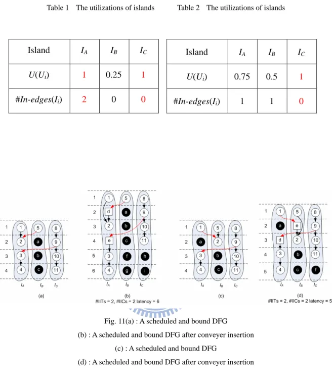
Given a scheduled DFG, two binding solutions are shown in Fig. 11(a) and Fig. 11(c). For Fig. 11(a), island utilizations are shown in Table 1. The number of in-edges incident to the island IK is defines as #in-edge(IK). From Table 1, the maximum utilization islands are island A
and island C. Their corresponding in-edges, #in-edge(IA) and #in-edge(IC), are 2 and 0. During
conveyer insertion, we insert a conveyer D between v5 and v2, and a conveyer E between v9
and v3. Finally, the latency increases from 4 csteps to 6 csteps in Fig. 11(b). For Fig. 11(c),
island utilizations are shown in Table 2. From Table 2, the maximum utilization is island C. Its corresponding in-edges, #in-edge(IC), is 0. During conveyer insertion, we insert a conveyer D
between v9 and v3, and a conveyer E between v1 and v2. Finally, the latency increases from 4
Table 1 The utilizations of islands Table 2 The utilizations of islands
Fig. 11(a) : A scheduled and bound DFG
(b) : A scheduled and bound DFG after conveyer insertion (c) : A scheduled and bound DFG
(d) : A scheduled and bound DFG after conveyer insertion
The result, shown in Fig. 11(d), is better than the result shown in Fig. 11(b) in terms of the latency because the difference of island utilizations is minimal. From this example, we find out that the number of edges incident to islands with the maximum U(Ii) would also affect the final
latency. Island IA IBB IC U(Ui) 1 0.25 1 #In-edges(Ii) 2 0 0 Island IA IBB IC U(Ui) 0.75 0.5 1 #In-edges(Ii) 1 1 0
Chapter 5
Proposed Algorithm
5.1 Overview
The problem formulation of this work is as follows: Assume an IIT delay takes one cstep in DRFM-IID. Given a DFG and a resource constraint (the number of available islands), obtain a scheduled and bound DFG with the minimized latency.
Fig. 12 : The overall flow of the proposed algorithm
The overall flow of the proposed algorithm is shown in Fig. 12. Given a DFG (V,E), List Scheduling is first performed to obtain an initial scheduling result and followed by Island Assignment. Island Assignment is aware that binding nodes on the critical path to the same
island and reducing number of IITs can potentially minimize the latency. Therefore, the problem is formulated as a maximum cost flow problem and the criticality is taken into consideration. More details are described in Section 5.2. However, Island Assignment does not allow rescheduling and rebinding. During the process of Island Assignment, it only potentially estimates the latency, but not practically minimizes the latency. Hence, Iterative Latency Minimization is proposed to obtain a better result via rebinding and rescheduling. This phase is composed of IIT Refinement and Conveyer Insertion. The way used for IIT Refinement in this work is similar to KL partitioning [23]. During the process of Conveyer Insertion, we insert conveyers and preserve the data dependency. The related details are described in Section 5.3.
5.2 Island Assignment
As mentioned in Section 4.2, nodes on the critical path and the number of IITs should be the main concerns while binding. In this phase, we use the network flow-based partitioning method to bind nodes. The details are as following. Given a scheduled DFG, a weighted compatibility graph is built first, as depicted in Fig. 13. Cstep(vi) denotes the cstep at which
node i is scheduled. In Fig. 13(a), if cstep(vi) is smaller than cstep(vj), there exists an edgei,j in
the compatibility graph. For example, cstep(v1) is smaller than cstep(v5) in Fig. 13(a), then
there is an edge1,5 in the compatibility graph in Fig. 13(b). In the compatibility graph, a solid
line denotes this edge exists in DFG, and a dotted line denotes this edge does not exists in DFG.
Fig. 13(a) : A scheduled and bound DFG, #islands = 2 (b) : A compatibility graph
After building the compatibility graph, we add two pseudo nodes vS and vT. Then vS
Fig. 14 : A compatibility graph with pseudo source and sink
In a network flow, the weight of an edge, w(ei,j), is defined in (2).
, 0 , ( ) = 1+ ( ) , i, j i j i, j i, j e E W e cri e e E ∉ ⎧⎪ ⎨ ∈ ⎪⎩ (2)
In (2), if an edge in the compatibility graph does not exist in the original DFG, the weight of this edge is zero. If an edge in the compatibility graph exists in the original DFG, the weight of this edge consists of two terms – the first one represents an edge is a real data transfer, and the second represents the criticality. Conceptually, W(ei,j) indicates the latency
impact if the edgei,j becomes an IIT. In other words, the higher the weight of an IIT is, the worse
the latency can be.
The criticality of an edgei,j , cri(ei,j), is defined in (3).
1 ( ) = ( ) - ( ) i, j j i cri e
The slack of edgei,j is regard as the critical indicator between vi and vj, that is, edges with
smaller slacks are more critical. The following example shows edge weight calculation. 1 ( ) = 1 + = 2 (2 - 1) 1 1.2 W e ( ) = 1 + = 1.5 (3 - 1) 1.3 W e
Fig. 15 : An example of edge weight calculation
After properly setting the weights of all edges in the compatibility graph, Island Assignment problem is formulated as finding a solution in which the total weighted sum of all IITs is minimal. This binding problem can already be optimally solved by the max-cost flow algorithm described in [23]. Fig. 17 is an edge-weighted compatibility graph.In the end, v1, v5 and v3 are
bound on island A and v2 and v4 are bound on island B, as shown in Fig. 17.
5.3 Iterative Latency Minimization
As mentioned above, the algorithm for Island Assignment potentially minimizes the latency. However, further improvement can still be achieved by rebinding and rescheduling during inserting conveyers as long as the data dependency is still intact. The overall algorithm of Iterative Latency Minimization is depicted in Fig. 18. In this section, we consider operations within one cstep at a time. Each iteration consists of IIT Refinement and Conveyer Insertion. In IIT Refinement, horizontal rebinding operations can further minimize the number of IITs and the number of edges incident to islands with the maximum U(Ii), as mentioned in
Section 4.2. The related details of IIT Refinement are described in Section 5.3.1 and the related details of Conveyer Insertion are described in Section 5.3.2.
5.3.1 IIT Refinement
The proposed IIC refinement process is based on KL algorithm [24], which is broadly used in partitioning-related problem. Within the process, nodes and bubbles are swapped for IIT minimization. A swap can be made between two nodes or between a node and a bubble. Feasible swaps include two kinds of candidates, nodes and bubbles. Nodes are considered feasible only on following conditions: (i) nodes must be unlocked, (ii) in-edges of nodes are not from conveyers and (iii) nodes must be in the current cstep. Bubbles are considered feasible only if they are in the current cstep. For example, in Fig. 19, at cstep3, the feasible swap
candidates for v3 are { v10, bubbleb }. A feasible swap pair of node u and node/bubble v is
denoted as (u, v). All feasible swap pairs are collected into the feasible swap pair set (FSPS). As depicted in Fig. 19, FSPS are { (3,b), (10,b), (3,10) }.
Fig. 19 : A FSPS example
In IIT Refinement, the gain of a swap pair (u,v), as defined in (4), is denoted as gu,v. It
consists of two elements, E and T. All islands with the maximum utilization are collected into the maximum utilization island set (MUIS). E is the total number of reduced IITs into islands in MUIS. T is the number of reduced IITs. For example, in Fig. 20, we assume α is 10, and the gain of swap pair v3 and bubbleb , g3,b, is calculated in (6).
Fig. 20 : An example of swap gain calculation
After performing an actual swap, FSPS, MUIS, and gains of swap pairs are updated accordingly. The key steps of IIT refinement are described as follows:
1 2 = ( - ) + 10 * (1- 2) 3 3 3,b g (6) ∈ ∈ ⎛ ⎞ ⎛ ⎞ ⎜ ⎟ ⎜ ⎟ ⎜ ⎟ − ⎜ ⎟ ⎜ ⎟ ⎜ ⎟ ⎜ ⎟ ⎜ ⎟ ⎝ ⎠ ⎝ ⎠
∑
∑
' MUI MUI ' # ( # ( ) = MUIS MUIS i i ' i i I I In - edge I In - edge I E ) (5) begin doset all operation nodes unlocked compute gi,j, ∀(i,j)∈FSPS
m=0
while ( FSPS is not empty )
find a pair (i,j) with the largest gain, gi,j, from FSPS
lock vi and vj and store the gaingi,j into gm
= +
g E αT
update FSPS and recalculate the gains of pairs in FSPS m++
Find k, such that is maximized
0 k k m G =
∑
= gm If ( Gk > 0 ) for (m=0 to m=k)swap vi andvj , which is the swap pair (i,j) with the gain gm
while ( Gk > 0 )
end
Fig. 21(a) : The DFG at the beginning of the iteration (b) : The DFG at the end of the iteration
Table 3 The corresponding island information
For example, a partially scheduled and bound DFG is shown in Fig. 21(a).The maximum Island IA IBB IC ID
U(Ii) 0.6 0.6 1 0.8
U(Ii) is 1 and MUIS = {IC}. At the beginning, an IIT number equal to 5, the number of IITs
into islands in MUIS is 1. Initially, the gains of all feasible swap pairs in FSPF are calculated as follows: 1 1 = ( - ) + 10(0) = 0 1 1 3,6 g 1 5 = ( - ) + 10(-1) = - 11.5 1 2 3,f g 1 2 = ( - ) + 10(2) = 20 1 2 6,f g
Then the swap pair (6, b) is selected to be swapped and node 6 is locked after the swap. This process is not terminated until FSPS is empty. Table 4 shows the gain and the partial gain sum of the two consecutive feasible swaps in this iteration. As a result, only the first swap, including (6, b), is actually desired. The resultant DFG at the end of this iteration is shown in Fig. 21(b)
Table 4 Gain and partial sum of gain in one iteration
n-th swap 1 2 Swapped pair (v6,bubblef) (v3,bubblef)
Gain 20 0
5.3.2 Conveyer Insertion
Conveyer Insertion consists of two key steps, inserting conveyers and preserving the data dependency. In this phase, we consider IITs in the current cstep. However, not all IITs require conveyers in the destination. The following principles avoid inserting conveyers: (i) the input data is already in the island, and (ii) there are usable bubbles in the island. For example, as depicted in Fig. 22(a), edge3,2 should conventionally insert a conveyer at cstep4 on island A. In
accordance with principle (i), input data(from v3) is already on island A at cstep2. Therefore,
edge3,2 is deleted, a new edgeb,2 is added and no conveyer is needed. Another IIT, edge4,10,
should insert a conveyer at cstep4 on island C. In accordance with principle (ii), there is an
usable bubble in the island C. Therefore, bubble d becomes into a conveyer d at cstep3, edge4,d
and edged,10 are added, and edge4,10 is deleted. Finally, as depicted in Fig. 22(a), edge1,6
requires a conveyer C at cstep4 on island B to preserve the data dependency.
Chapter 6
Experimental Results
The proposed algorithm has been implemented in C++/Linux environment, and all experiments are conducted on a workstation with an Intel Xeon 3.2GHz CPU and 4GB RAM. The test cases are from different benchmark sets [25]–[27], which are frequently used in the high-level synthesis field. The basic information of these test cases (DFGs) is shown in Table 5. The first column shows the test case name, and the followings show the number of nodes, the number of edges of the DFGs, respectively, and the last one reports the latency obtained by ASAP scheduling with unlimited resources islands. For fair and comprehensive comparison, two different synthesis flows are presented, as shown in Fig. 23. Given an input DFG and a resource constraint, list scheduling is first performed to provide an initial scheduling result for both flows. Flow1 implements the approach proposed in [9] and Conveyer Insertion; Flow2 applies the algorithm proposed in this work.
Two configurations are considered in our experiments – synthesis is performed without/with a resource constraint in Configuration 1/2, respectively. In the first configuration, the number of islands is set as the minimum number that still guarantees the synthesis outcome with the minimum latency indicated in Table 5. In Configuration 2, the number of islands is reduced by half as:
⎡ ⎤
⎢ ⎥
⎢ ⎥
number of islands in Config. 1 number of islands in Config. 2 =
The results of the Configuration 1 are shown in Table 6, and Table 7, respectively. Table 6 gives the latency result and Table 7 reports the result of number of IITs and the result of number of IICs. The results of the Configuration 2 are shown in Table 8 and Table 9 and, respectively. Table 8 gives the latency result, Table 9 reports the result of number of IITs the result of number of IICs. In Table 6, the second column is the number of the given islands, and the third one is the latency of DFGs after list scheduling is applied; the fourth is the latency by Flow1, the fifth is the latency by Flow2 and the sixth is the percentage of reduction in terms of the latency. In Table 7, the second column is the number of the given island, the third one is the number of IITs by Flow1, the forth one is the number of IITs by Flow2, and the fifth one is the percentage of reduction in terms of the number of IITs; The sixth one is the number of IICs by Flow1, the seventh one is the number of IICs by Flow2 and the eighth one is the percentage of increment in terms of the number of IICs.
The experiment results showed that latency was reduced by the proposed algorithm on average by 17.62% without resource constraints (i.e., configuration 1); the number of IITs was reduced by the proposed algorithm on average by 28.27% and the number of IIC was increased by the proposed algorithm on average by 36.76%. In conclusion, the area and the performance are trade off in experimental results.
In Table 8, the second column is the number of the given island, and the third one is the latency of a DFG after list scheduling is applied; the fourth is the latency by Flow1, the fifth is the latency by Flow2 and the sixth one is the percentage of reduction in terms of the latency. In Table 9, the second column is the number of the given island, the third one is the number of IITs by Flow1, the forth one is the number of IITs by Flow2, and the fifth one is the percentage of reduction in terms of the number of IITs; The sixth one is the number of IICs by Flow1, the seventh one is the number of IICs by Flow2 and the eighth one is the percentage of increment in terms of the number of IICs.
reduced by the proposed algorithm on average by 37.54% and the number of IIC was increased by the proposed algorithm on average by 32.86%. In the experimental results, the area and the performance are trade off. Moreover, when the number of islands decreased, the improvement of the latency increased. However, the number of IICs did not increase like that.
Table 5 The basic information of benchmarks
Test case #nodes #edges ASAP latency
wang 48 58 7 lee 49 62 9 feedback 53 50 7 h2v2 53 54 17 fft4 62 88 8 cosine1 66 76 8 writebmp 106 88 7 matmul 109 116 9 smooth 197 196 11 invert 333 354 11
Table 6 Experimental results of the latency in Configuration 1.
Table 7 Experimental results of IITs and IICs in Configuration 1.
#IITs Reduction #IICs Increment Test case #islands
Flow1 Flow2 2 to 1 Flow1 Flow2 2 to 1 wang 8 39 26 33.33% 17 21 23.53% lee 6 32 20 37.50% 11 14 27.27% feedback 9 27 18 33.33% 12 17 41.67% h2v2 4 24 17 29.17% 6 9 50.00% fft4 8 63 45 28.57% 24 34 41.67% cosine1 9 48 33 31.25% 20 29 45.00% writebmp 16 29 25 13.79% 18 26 44.44% matmul 16 39 38 2.56% 27 38 40.74% smooth 27 91 67 26.37% 49 63 28.57% invert 36 175 93 46.86% 77 96 24.68% Avg. 28.27% 36.76% Latency(#csteps) Reduction Test case #islands #csteps
Flow1 Flow2 2 to 1 wang 8 7 16 12 25.00% lee 6 9 17 14 17.65% feedback 9 7 13 11 15.38% h2v2 4 17 32 27 15.63% fft4 8 8 21 16 23.81% cosine1 9 8 16 15 6.25% writebmp 16 7 13 11 15.38% matmul 16 9 16 14 12.50% smooth 27 11 21 16 23.81% invert 36 11 24 19 20.83% Avg. 17.62%
Table 8 Experimental results of the latency in Configuration 2
Table 9 Experimental results of IITs and IICs in Configuration 2
Latency(#csteps) Reduction Test case #islands #csteps
Flow1 Flow2 2 to 1 wang 4 13 26 20 23.08% lee 3 18 36 25 30.56% feedback 4 14 28 20 28.57% h2v2 2 29 43 26 39.53% fft4 4 16 37 29 21.62% cosine1 4 17 34 24 29.41% writebmp 8 14 24 19 20.83% matmul 8 15 29 21 27.59% smooth 13 17 37 23 37.84% invert 18 20 42 28 33.33% Avg. 29.24%
#IITs Reduction #IICs Increment Test case #islands
Flow1 Flow2 2 to 1 Flow1 Flow2 2 to 1 wang 4 35 24 31.43% 16 12 -25.00% lee 3 36 23 36.11% 6 6 0.00% feedback 4 31 14 54.84% 8 10 25.00% h2v2 2 16 13 18.75% 2 2 0.00% fft4 4 58 44 24.14% 10 12 20.00% cosine1 4 46 26 43.48% 8 11 37.50% writebmp 8 42 27 35.71% 14 24 71.43% matmul 8 68 37 45.59% 19 28 47.37% smooth 13 111 69 37.84% 32 65 103.13% invert 18 204 107 47.55% 63 94 49.21% Avg. 37.54% 32.86%
Chapter 7
Conclusion
In this work, we proposed DRFM-IID, which takes IIT delay into consideration. On DRFM-IID, we develop an architecture synthesis flow for latency minimization. Island Assignment is first performed. It maps operations onto islands by network flow-based partitioning. Next, Iterative Latency Minimization is applied. It consists of two terms — IIT Refinement and Conveyer Insertion. IIT Refinement rebinds operations between islands to derive a better solution and Conveyer Insertion inserts conveyers into the DFG. The experimental results indicate that latency can be reduced by 17.6% ~ 29.2% on average.
References
[1] International Technology Roadmap for Semiconductors. Semiconductor Industry Association, 2005.
[2] D. Matzke, “Will physical scalability sabotage performance gains?” IEEE Computer, vol.20, pp. 37–39, 1997.
[3] L. P. Carloni and A. L. Sangiovanni-Vincentelli, “Coping with latency in SOC design,” IEEE Micro, vol. 22, pp. 24–35, 2002.
[4] N. Magen, A. Kolodny, U. Weiser, and N. Shamir, “Interconnect-power dissipation in a microprocessor,” Proc. Int’l Workshop System Level Interconnect Prediction, pp. 7–13, 2004.
[5] Singh, G. Parthasarathy, and M. Marek-Sadowska, “Efficient circuit clustering for area and power reduction in FPGAs,” ACM Trans. Design Automation of Electronics Systems, vol. 7, no. 4, pp. 643–663, Oct. 2002.
[6] E. Kusse and J. Rabaey, “Low-energy embedded FPGA structures,” Proc. Int’l Symp. Low Power Electronics and Design, pp. 155–160, 1998.
[7] D. M. Chapiro, “Globally-asynchronous locally-synchronous systems,” Ph.D. dissertation, Stanford Univ., Stanford, CA, 1984.
[8] L. P. Carloni, K. L. McMillan, A. Saldanha, and A. L. Sangiovanni-Vincentelli, “A methodology for correct-by-construction latency insensitive design,” Proc. Int’l Conf. Computer Aided Design, pp. 309–315, 1999.
[9] J. Cong, Y. Fan, and W. Jiang, “Platform-based resource binding using a distributed register-file microarchitecture,” Proc. Int’l Conf. Computer Aided Design, pp. 709–715, 2006.
register-file microarchitecture,” Proc. Design Automation Conf., pp. 765–770, 2007. [11] D. Kim, J. Jung, S. Lee, J. Jeon, and K. Choi, “Behavior-to-placed RTL synthesis with
performance-driven placement,” Proc. Int’l Conf. Computer Aided Design, pp. 320–325, 2001.
[12] J. Jeon, D. Kim, D. Shin, and K. Choi, “High-level synthesis under multi-cycle interconnect delay,” Proc. Asia South Pacific Design Automation Conf., pp. 662–667, 2001.
[13] J. Cong, Y. Fan, G. Han, X. Yang, and Z. Zhang, “Architecture and synthesis for on-chip multicycle communication,” IEEE Trans. Computer-Aided Design Integrated Circuits and Systems, vol. 23, no. 4, pp. 550–564, Apr. 2004.
[14] C.-I Chen and J.-D. Huang, “CriAS: A performance-driven criticality-aware synthesis flow for on-chip multicycle communication architecture,” Proc. Asia and South Pacific Design Automation Conf., pp. 67–72, Jan. 2009.
[15] S.-H. Huang, C.-H. Chiang, and C.-H. Cheng, “Three-dimension scheduling under multi-cycle interconnect communications,” IEICE Electronics Express, vol. 2, no. 4 pp.108–114, Feb. 2005.
[16] J. Cong, Y. Fan, and Z. Zhang, “Architecture-level synthesis for automatic interconnect pipelining,” Proc. Design Automation Conf., pp. 602–607, 2004.
[17] W.-S. Huang, Y.-R. Hong, J.-D. Huang, and Y.-S. Huang, “A multicycle communication architecture and synthesis flow for global interconnect resource sharing,” Proc. Asia and South Pacific Design Automation Conf., pp. 16–21, 2008.
[18] Y.-J. Hong, Y.-S. Huang, and J.-D. Huang, “Simultaneous data transfer routing and scheduling for interconnect minimization in multicycle communication architecture,” Proc. Asia and South Pacific Design Automation Conf., pp. 19–24, Jan. 2009.
[19] Ohchi, N. Togawa, M. Yanagisawa, and T. Hothuki, “High-level synthesis algorithms with floorplanning for distributed/shared-register architectures,” Proc. Int’l Symp. VLSI
[20] S. Gao, K. Seto, S. Komatsu, and M. Fujita, "Pipeline scheduling for array based reconfigurable architectures considering interconnect delays," Proc. Int’l Conf. Field-Programmable Technology, pp. 137–144, Dec. 2005.
[21] Altera website. [Online]. Available: http://www.altera.com
[22] Xilinx website. [Online]. Available: http://www.xilinx.com
[23] R. Ahuja, T. Magnanti, and J. Orlin, Network flows: theory, algorithms, and applications, Prentice Hall, Inc., 1993.
[24] B. Kernighan and S. Lin, “An efficient heuristic procedure for partitioning graphs,” Bell System Technical Journal, pp. 291–307, Feb. 1970.
[25] MCAS: multicycle architectural synthesis system. [Online]. Available:
http://cadlab.cs.ucla.edu/software_release/mcas/
[26] ExPRESS group. [Online]. Available: http://express.ece.ucsb.edu/
[27] T. Cormen, C. Leiserson, R. Rivest, and C. Stein, Introduction to algorithms, 2nd edition, the MIT press, 2001.
[28] D. Herrmann and R. Ernst, “Improved interconnect sharing by identity operation insertion,” Proc. IEEE/ACM Int’l Conf. Computer Aided Design, pp. 489–493, 1999. [29] M. Potkonjak and S. Dey, “Optimizing resource utilization and testability using hot potato
techniques,” Proc. Design Automation Conf., pp. 201–205, 1994.
[30] C.-I Chen, Y.-T. Lin, W.-L. Hsu, and J.-D. Huang, "Communication synthesis for interconnect minimization targeting distributed register-file microarchitecture," Proc. Electronic Technology Symposium, Jun. 2009.