PROCESSING AND MICROSTRUCTURE OF NANO-Mo/Al
2O
3COMPOSITES FROM MOCVD AND FLUIDIZED BED
Ching-Jang Lin, Chih-Chung Yang and Wen-Cheng J. Wei*
Institute of Materials Science and Engineering, National Taiwan University, Taipei,Taiwan 106, Republic of China (Received May 10, 1999)
(Accepted July 8, 1999)
Abstract—The process utilizing metal-organic chemical vapor deposition (MOCVD) was conducted in a fluidized
Al2O3powder bed for the preparation of nano-Mo ceramic composites. During the process, Mo species were deposited in fine Al2O3ceramic powder using a pyrolysis of Mo carbonyl. The composition and crystallinity of the intermediate phases of Mo2CxOy, and the microstructure of the coated particles and coated layer were analyzed using XRD/SEM/ TEM techniques. The granulated powder was then treated by H2reduction, pressureless sintering or hot-pressing in a vacuum, which could achieve densities better than 99% T.D. The densification, wear, and microstructural properties of the dense nano Mo-composites were then investigated and discussed. It is seen that the nano-inclusion of Mo grains inhibited the grain growth of the alumina matrix, which had a mean grain size of either 4.9m or 1.2 m, as the volume fraction of Mo increased from 0 vol% to 5 vol%. The wear resistance of the nano-Mo/Al2O3 was approximately 2 times better than that of pure Al2O3. Through an understanding of the pyrolysis of Mo(CO)6and grain growth kinetics of Mo-species growth kinetics, the morphology and size of the Mo grains in ceramic composites can be modified. ©2000 Acta Metallurgica Inc.
Introduction
Several breakthroughs have been made in the past decade in high performance ceramics that possess properties capable of changing the traditional image of ceramic materials. The successful preparation of nano-size composites (1,2) may be the one of the strongest impacts on the ceramic community.
Nanocomposite materials are defined as composites of more than one Gibbsian solid phase where at least one of the phases shows dimensions in the nanometric range (1). Composites with nano-powder are reported to be good in mechanical properties and in reliability with the help of microstructural modification with reduced inherent flow size (3,4). In comparison, the classical ceramic processing routes using ultrafine (⬍50 nm) ceramic powder may hold certain disadvan-tages (5). Strong agglomeration and poor dispersion problems, for example, are two major concerns in colloidal processing (5,6).
Metallic particulates used as the reinforced phase have innate properties, such as plastic and electric conductivity. Transition metals, such as Ni, Cr, Mo, W melt at high temperature and have a high elastic modulus. However, the thermal expansion coefficient (TEC) of these metals show a wide range, from 4.59*10⫺6/°C (for W), or 5.43*10⫺6/°C (for Mo), to a fairly high value of 19.2*10⫺6/°C (for Ag) (7). The mismatch between the metallic inclusion and ceramic matrix generates various types of reinforce-ment. When considering electrical conductivity, TEC mismatches, melting points, and Young’s mod-ulus, the optimized choice of the metallic phase for making structural ceramic composite is W or Mo.
* Corresponding author: 1 Roosevelt Rd., Section 4, Taipei, Taiwan, 106, R.O.C.
Pergamon
NanoStructured Materials, Vol. 11, No. 8, pp. 1361–1377, 1999 Elsevier Science Ltd Copyright © 2000 Acta Metallurgica Inc. Printed in the USA. All rights reserved. 0965-9773/99/$–see front matter
PII S0965-9773(00)00433-5
Mo reinforced ceramic composites have been studied by several researchers (8 –11). Recently, Nawa
et al. (8,9) conducted a ball-milling process using acetone as the solution to prepare fine Mo/Al2O3and
W/Al2O3mixtures. The fracture strength and toughness of the hot-pressed composites are significantly
improved. In addition to wet-processing methods, a gas reaction technique can be utilized to synthesize nano-sized powder mixtures, a technique, which enables the growth of nanometric particles to start from a molecular-scale phase.
Chemical vapor deposition (CVD) and fluidized powder bed processes are two mature and com-mercial techniques widely used in the semiconductor and chemical engineering industries. McCreary (12) first reported the combination of processes used to deposit high atomic number metals (such as Ni, Mo, and Re) on micro-spherical glass in fluidized beds. The sources of the metallic phase were obtained from the pyrolysis of metal carbonyls at a reduced atmosphere.
MOCVD is one of the gas reaction processes. Wei and Lo (13,14) have extensively reviewed the process and properties of the (Mo, Cr) oxycarbides on various substrates, e.g. stainless steel and SiC, prepared using the metal-organic CVD (MOCVD) process. There were several concerns, however, about the processing conditions, including low deposition pressure, ultrafine particle size and agglom-eration during deposition, etc. If the MOCVD process can be conducted in a fluidized powder reactor, it can potentially lead to nanometric dispersoid and homogeneous coating on submicron ceramic powders (15).
Wear properties among all the mechanical properties of nano-sized ceramic composites reported in literature (16 –19) showed the most consistent results. The pinning of grain boundaries by these secondary inclusions resulted in a smaller grain size and wavy grain boundaries. The matrix grains are interlocking, therefore, the microstructure displays better performance in the wear resistance of the nano-SiC/Al2O3.
Modulus mismatch causing a change in the fracture mode in ceramic composites may also be responsible for the improvement in toughness of some nanocomposites. Huang and Lin (20) studied WC/Si3N4 ceramic composites and the role of elastic property mismatch in the failure of ceramic
composites. The fracture may involve various mechanisms of crack-branching, crack-deviation, and/or crack-arrest, but the strength of composites increased when the initial crack was subcritically extended and arrested at the interface of the matrix. Strengthening and toughening are evident with the secondary metallic phase.
The objectives of the present study are several. The fabrication of the nano-Mo/Al2O3composite by
a new process— conducting MOCVD in a fluidized powder reactor—is the primary objective. Special emphasis is placed on the pyrolysis sequence of Mo(CO)6and the growth mechanisms of Mo-species
in the H2reduction stage. Secondly, the densification and characterization of the composite are also
conducted. The distribution of Mo inclusions may resolve the homogeneity and the interaction of the metallic grains with matrix Al2O3. As a consequence, the mechanical properties, e.g. wear resistance,
could be improved. Finally, the relationship between microstructure and wear property of the nano-composite is studied and discussed.
2. Experimental 2.1 Processing Operation
The fluidized powder reactor and an MOCVD system are constructed based on the schematic diagram shown in Fig. 1. Molybdenum hexacarbonyls (Mo(CO)6, Alfa Chemicals Co., MA, USA) were placed
in a source chamber and carried by N2gas (99.9% pure) at a flow rate of 0.5 to 2.0 l/min. Deposition
vapor flowed through the bottom of the fluidized powder bed and deposited on the fluidizing alumina powder (AKP-50, Sumitomo Chemical Co., Japan) which was preheated in a dry oven at 105°C and left overnight. Two gas outlets were attached to the top of the reactor, one for the measurement of absolute-pressure using a gauge with a variable capacitance sensor (MKS-Baratron, type 122A), the other, for vacuuming using a rotary pump installed with a cold trap system in front of the connection. According to Lander’s results (21), molybdenum carbonyl [Mo(CO)6] evaporates readily in a
vacuum system with a saturation pressure P:
logP*⫽ 11.795 ⫺ 3800/T,
where T is the reaction temperature in Kelvin. The saturation pressure P of the carbonyl is 10.7 torr at 80°C. The source chamber was maintained at the pressure and kept at a constant 80°C in a water bath. When the temperature of the reactor was reached, a gas pressure of 10 torr was maintained through the whole coating stage. The coating temperature in the reactor was kept either at 250°C, 325°C or 400°C, and at a constant flow rate of N2in 2.0 l/min. The process was normally conducted for 2 hr or lasted
for 1 to 4 hr when the coating temperature 325°C was selected.
In order to avoid the uncertainty of powder fluidization, the minimum fluidization velocity (Umf) had
to be determined (22–26). The flow rate was adjusted and controlled at 2000 ml/min of which was larger than the Umf(ca. 736 ml/min) in this MOCVD process. Larger agglomerates (⬎20m) or heavy
particles (coated with high density Mo-species) required greater floating forces which could be supplied by a greater flow rate. The deposited powder and a pure AKP-50 alumina (Sumitomo Chemical Co., LTD., Japan) were either pressureless sintered at 1600°C for 1 hr in H2/Ar atmosphere (Tungsten-mesh
furnace, Centorr Co., USA) or hot-pressed at 1400°C for 1hr in a vacuum. (High-Multi 5000 HP furnace, Fujidempa Kogyo Co., Ltd., Japan).
Figure 1. Schematic diagram of the MOCVD and fluidized powder bed equipment used in this research.
NANO-Mo/Al2O3COMPOSITES 1363
2.2 Characterization of Nanocomposites
The density variation of molybdenum oxycarbide deposited powder was measured using a pycnometer (Ultrapycnometer 1000, Quantachrome Co., USA). The thermogravimetric analyzer (TGA, Thermal Analyst 2000, DuPont Co., USA) was used to analyze the pyrolysis behavior of the composite powder processed at the temperature of either 250°C, 325°C or 400°C. The heating rate was 10°C/min tested in a constant flow of 5% H2/N2atmosphere.
Crystalline phases of the deposited powder were identified with an X-ray diffractometer (XRD, PW1729, Philips Co., Holland). The morphology of deposited powder, the microstructure and com-position of the sintered bulk were analyzed by a TEM (100CX⌱⌱, JEOL Co., Japan) or an SEM (XL30, Philips Co., Holland) equipped with an X-ray energy dispersive spectroscopy (EDS, DX-4, EDAX Co., USA).
In this study, the wear resistance of pure alumina (AKP-50) and Mo/alumina was investigated using a wear tester (Multi-Purpose Friction and Wear Tester, TE53/7891, Plint & Partners Ltd., England). The test was performed under dry conditions, against an 800-mesh diamond wheel with a constant load of 42 N and under a constant rate of 200 rpm (equivalent to 0.1 m/s).
3. Result and Discussion 3.1 Density Variation
The density of the composite powder measured by pycnometer increases from 3.986 g/cm3of pure
alumina powder to 4.033 g/cm3of the deposited powder. The deposited powder was tested by the
semi-quantitative analysis of SEM-EDS which revealed 8 wt% of molybdenum species in the alumina powder. The density and EDS results of the composite powder show that Mo species have been incorporated in the alumina powder.
The density of pressureless sintered Mo/Al2O3 block (MA3-1) is 3.59 g/cm3. Under the same
sintering conditions, a pure alumina sample (AKP-50) shows a sintered density of 3.934 g/cm3, which
is equal to a 98.7% theoretical density (T.D.). The density of the hot-pressed composite block is 4.05 g/cm3(MA3-2/HP) and the open porosity is less than 0.02 vol%.
3.2 Pyrolysis of Molybdenum Carbonyl
Lander (21) first reported the use of metal carbonyls as the sources for metallic coatings. The vapor of Mo carbonyl was thermally pyrolyzed, then deposited on a substrate to form metal-related phases. In the early reports (27,28), the deposited film was characterized as a metal phase. However, minor contents of carbon or oxygen in the films found by those researchers were treated as impurities. The crystal structure of the ‘Mo metal’ phase of the coatings was indexed to be a face-centered cubic (FCC) structure, not the body-centered cubic (bcc) structure of molybdenum at room temperature. Recently, Ferguson et al. (29) have pointed out that the structure of the deposited phase is similar to Mo2C with
the chemical composition falling between Mo2C0.7O0.6and Mo2C0.6O0.5. In addition, Wei and Lo (14)
have studied the properties of the (Mo, Cr) oxycarbides under a similar MOCVD process. They reported that the coating phase of molybdenum carbonyl is Mo2CxOy, structurally similar to Mo2C, but the
composition and crystalline structure may vary with deposition conditions (temperature and pressure). McCreary (12) reported that molybdenum carbonyl sublimated at 315K and pyrolysized to Mo metal and CO gas at 623K. The given pyrolysis sequence is oversimplified due to the lack of knowledge of the effects of deposition temperature. Three TGA curves of the composite powders obtained either at
250°C, 325°C or 400°C are shown in Fig. 2. Each curve has two stages of weight loss. The drifting of the curves, which occurred from 50 to 100°C, is due to the shift of the base-line to the equilibrium condition of the TGA instrument. The first weight loss happens from 490 to 618°C and the second weight loss occurs between 718 to 883°C as tested in 5%H2/N2atmosphere. The first and second stages
of weight loss, either 0.6 wt% or 2.0 wt%, are caused by the reduction of Mo-species. The reduction is first transformed to MoO2, then to the Mo phase.
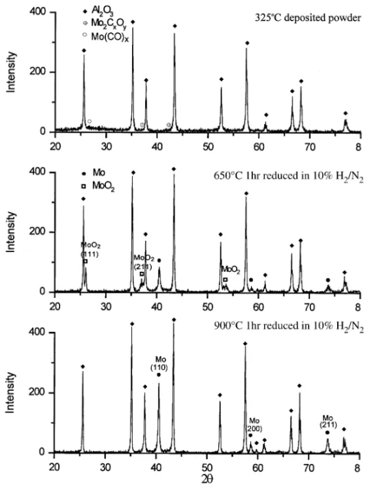
In order to confirm the TGA results, we selected 650°C and 900°C as the temperatures of the heat treatment. The composite powders in different stages of the heat treatment were analyzed by XRD. Fig. 3 displays the XRD results of a 5 vol% Mo/Al2O3deposited powder at the temperatures in an H2/N2
atmosphere. The spectra show that the 325°C as-deposited phase is an amorphous molybdenum oxycarbide, resulting in the broadening of the XRD peak from 22° to 30° (2 angle). With the treatment at a higher temperature, the amorphous phase in deposited powder decomposes and forms the MoO2
crystalline phase at 650°C treated for 1hr, and further reduces to Mo metal at 900°C for 1hr in 10%H2/N2atmosphere.
The pyrolysis occurs through the breakage of Mo-(CO) bonds in the fluidizing powder bed reactor, and can be shown as the following sequential reactions:
80°C in 10 torr
Mo(CO)6(s)3 Mo(CO)x(g)⫹ (CO)6-x(g) (1)
50°C to 400°C in flowing N2
Mo(CO)x(g)3 Mo2CxOy (s)(amorphous) (2)
490°C to 620°C in 10%H2/N2
Mo2CxOy (s)3 MoO2(s)(crystalline)⫹ H2O(g)⫹ CO2(g) (3)
650°C to 900°C in 10%H2/N2
Figure 2. TGA results of Mo2CxOy/Al2O3powders obtained at various deposited temperatures (a) 250°C, (b) 325°C, and (c)
400°C. The testing condition is 10°C/min in 5% H2/N2atmosphere.
NANO-Mo/Al2O3COMPOSITES 1365
MoO2(s)3 Mo(s)(crystalline)⫹ H2O(g) (4) 3.3 Microstructure and Microstructural Development
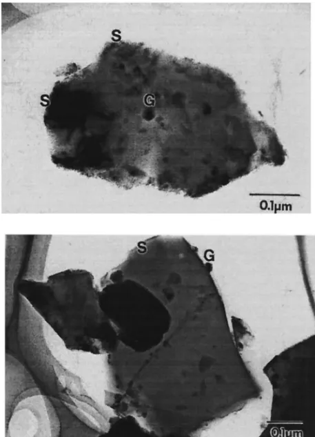
3.3.1 Deposited Particles and Sintered Block. TEM morphology of several Mo-species/Al2O3particles
prepared from the MOCVD in the fluidized powder bed is shown in Fig. 4. The coating features can be divided into two types, either smooth coating ‘S’ or granular deposits ‘G’. The features of the granular surface are irregular with darker spots of sizes ranging from 6 nm to 30 nm. In addition, certain area is covered with a smooth amorphous film of Mo-species on Al2O3particles. These features as
indicated with ‘S’ markers (in Fig. 4) show the atomic adsorption effect on the electron beam. The contrast in the coating region changes gradually.
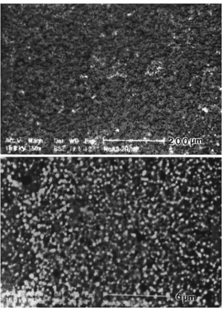
The SEM morphologies of one pressureless sintering composite are shown in Fig. 5(a). The homogeneity of the sintered Mo/Al2O3nanocomposite is in the scale of 50 –150m (Fig. 5(a)) and the
composition of the brighter (marker “b”) and darker area (marker “d”) contain 15 wt% or 5 wt% of Mo which was quantified by the EDS. The correspondent EDS pattern of bright (“b”) regions is shown in Fig. 5(b). The inhomogeneity of pressureless sintered sample is a matter of agglomerate formation caused by non-uniformity in the fluidizing bed. However, the inhomogeneous structure will be prevented when hot-pressing is utilized. Fig. 6 shows the polished surfaces of hot-pressed composites, which use the same batch of composite powder as in Fig. 5(a). The agglomeration features in the scale of 200m are hardly observed, as shown in Fig. 6. Instead, submicron Mo features in bright contrast are still evident. Hot pressing and the atmosphere (vacuum) play an important role in the homogeni-zation of the texture. During the previous coating process, only the minimal segregation of Mo and maximal homogeneity in hot-pressed composites were obtained when the agglomeration and second-phase additives were well dispersed in composite powder.
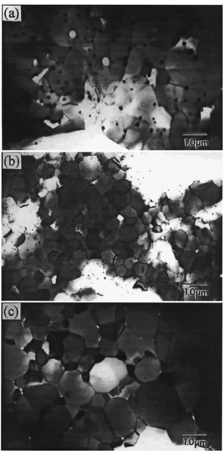
A series of TEM micrographs of three dense Mo/Al2O3composites are shown in Fig. 7 illustrating
Al2O3composites with various types of Mo distribution. Fig. 7(a) shows the MA3-2 sample, which was
pressureless-sintered at 1600°C for 1 hr in an H2/Ar atmosphere and consisted of 5 vol% Mo in sizes
Figure 4. TEM micrographs of the composite particles.
NANO-Mo/Al2O3COMPOSITES 1367
of 50 to 200 nm. Most of the Mo grains are inter-granular, and the average grain size of Al2O3is 1.2 m in this MA3-2 composite.
The MA3-1 sample contained 2 vol% Mo grains in sizes of 5 to 50 nm sintered under the same conditions as in the previous sample (MA3-2), as shown in Fig. 7(b), revealing an average grain size of 0.8m Al2O3matrix. Fig. 7(c) is the morphology of the MA3-2/HP sample, which contains 5 vol%
Mo in sizes of 50 to 700 nm. The MA3-2/HP was hot-pressed at 1400°C for 1 hr in a vacuum atmosphere. The average grain size of the Al2O3in Fig. 7(c) is 1.6m. The Mo phase with a large size
distribution could be the result of the variation of crystallization behavior and grain growth at the sintering temperature.
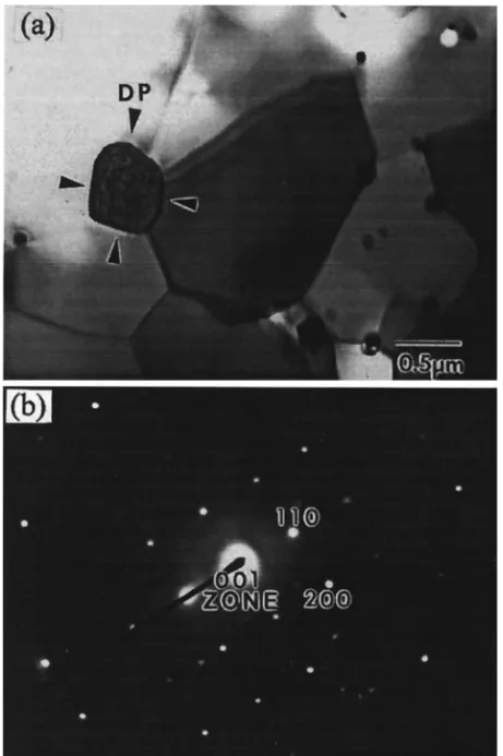
A bright-field (BF) TEM micrograph of an Mo grain at the boundaries of Al2O3grains is shown in
Fig. 8. The corresponding diffraction pattern (DP) is indexed as the crystalline BCC phase of Mo. Clean interface between Mo/Al2O3 is evident. A higher content of Mo in Al2O3 matrix inhibits the grain
Figure 5. (a) SEM micrograph of 15 wt% Mo/Al2O3nanocomposite imaged by back scattered (BS) mode; (b) EDS pattern of the “b” region pointed in the micrograph. The sample was pressureless-sintering in H2/Ar atmosphere
growth of Al2O3. In the opposite case, fewer (⬍5 vol%) and finer (⬍50 nm) Mo grains can not
effectively inhibit the coarsening of Al2O3. These finer Mo grains are likely engulfed in Al2O3grains
as they grow. In this composite system, the mean grain size of Al2O3matrix decreases to 1.2m as the
volume fraction of second-phase Mo content increases to 5 vol% with pressureless sintering at 1600°C for 1 hr in H2/Ar atmosphere.
3.3.2 Grain Growth Mechanism. The TEM studies on Mo/Al2O3 nanocomposites reveal that Mo
grains belonging to inter- and/or intra-granular are controlled by pyrolysis reactions, the volume fraction of Mo, and the sintering atmosphere. The amorphous phase nucleated to form MoO2below
620°C, and further reduced to metal Mo at elevated temperatures. The crystallization and grain growth of Mo took place before the rearrangement of Al2O3 grain in the first stage of sintering. The grain
growth of the Mo phase may be due to the transport of Mo-species by diffusion either along the surface or on the grain boundaries of the matrix.
The primary reason for the production of intra-type Mo is mainly induced by the grain growth of Al2O3in sintering stage. The dragging force of these fine Mo (⬍200 nm) is not strong enough to pin
the grain boundary of Al2O3in position. As a result, the Mo is engulfed in the growing Al2O3. Under
opposite conditions, large Mo grains stayed at Al2O3grain boundaries throughout the entire sintering
Figure 6. SEM micrographs in different magnifications imaged by back scattered (BS) mode. The composite was prepared by hot-pressing (HP) in vacuum atmosphere.
NANO-Mo/Al2O3COMPOSITES 1369
process, resulting in smaller Al2O3grains. Previous results of the grain sizes could be interpreted with
the Zener relation (30,31), Rc⫽ 4r/3Vf, where r and Vf are the radius and the volume fraction of the
Figure 7. TEM micrographs of three sintered Mo/Al2O3composites with (a) intergranular nano-sized Mo grains, (b) inter- and intra-Mo grains in the MA3-1 sample, and (c) inter-submicron and intra-nano-sized Mo grains in the MA3-2/HP sample
second phase, respectively. This simple and approximate relationship shows that the critical size (Rc) of the matrix grains decreases as the particle size of effective inclusions decrease and the volume fraction increases.
The partial pressure of oxygen is still high enough to form MoO2 and MoO3 phases (32) at
temperature below 1200°C when sintering under a rough vacuum condition. Sintering the composites containing Mo in an H2atmosphere can avoid the formation of the MoO2or MoO3phase. The melting
point of Mo is 2610°C. The neck growth of Mo particles may occur at 1200°C. However, densification (or large shrinkage) of Mo particles is apparent at temperatures higher than 1600°C due to the low diffusion rate of Mo in the H2/Ar atmosphere. The results depict that the microstructure of Mo/Al2O3
is controlled by the content of Mo and a sintering atmosphere.
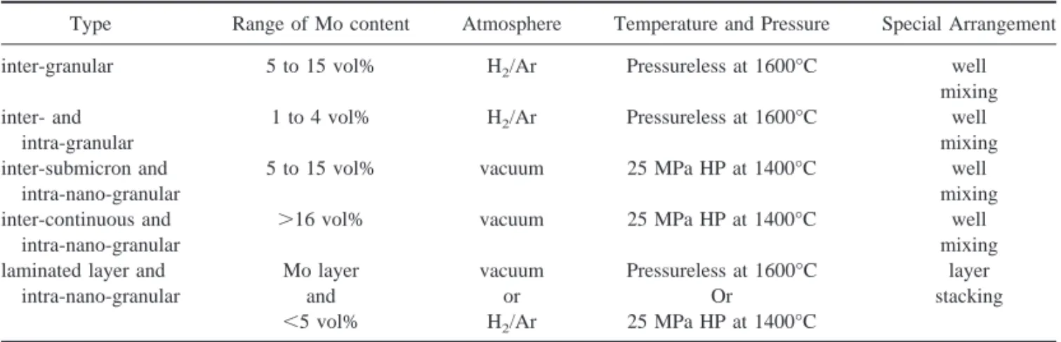
From the results, it can be seen that the microstructure of the composite can be designed by adjusting or optimizing processing parameters, such as the content of Mo, the sintering atmosphere, temperature, pressure, and special arrangement of powder packing to fabricate at least five types of the Mo Figure 8. (a) Bright-field micrograph of Mo/Al2O3, and (b) diffraction pattern of the Mo as pointed “DP” in the micrograph.
NANO-Mo/Al2O3COMPOSITES 1371
metal/ceramic nanocomposite. The conditions that are optimal for the fabrication of different types of the nanocomposite are shown in Table 1. The features of microstructures of Mo grains in Al2O3matrix
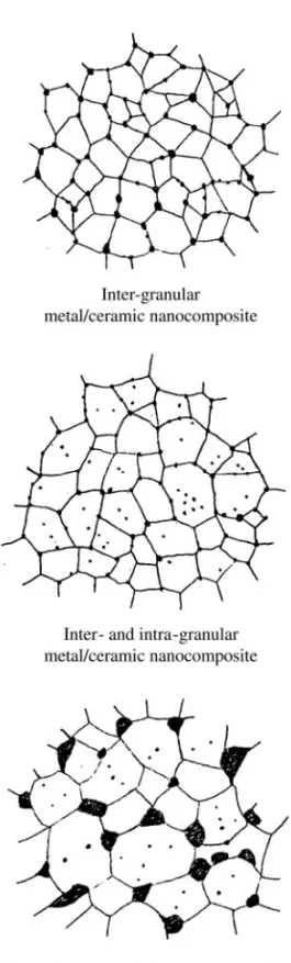
could be (a) pure inter-granular, (b) inter- and intra-granular, (c) inter-submicron and intra-nano-granular, (d) inter-continuous and intra-nano-intra-nano-granular, or (e) laminated layer and intra-nano-granular Mo/Al2O3nanocomposites. Three schematic diagrams are shown in Fig. 9 to reveal two-dimensional
features of the metal/ceramic nanocomposites. 3.4 Wear Resistance
The relationship between Mo/Al2O3composites and wear results of the samples is shown in Table 2
which lists the processing conditions of the samples, the sintered density, wear test parameters, and wear resistance results. The preliminary testing results showed that the diamond wheel should be dressed after every four thousand cycles in order to maintain good surface conditions. Therefore, the wear was tested under the conditions similar to those of the diamond wheel.
The wear results of pure alumina and Mo/Al2O3are shown in Fig. 10. The wear rate of pure alumina
is nearly two times greater than that of Mo/Al2O3composites, either MA3-1 or MA3-2. It is believed
that the addition of nano-sized molybdenum to aluminum oxide helps improve the wear resistance of pure alumina. First of all, a higher content of Mo in the Al2O3matrix inhibits the grain growth of Al2O3.
The refinement of the matrix grains can remarkably decrease the grain size and critical flow size, which probably enhance the mechanical properties of the surface layer (16).
The wear resistance of the MA3-2/HP is superior to pure Al2O3, but inferior to that of MA3-1 or 3-2.
The sintering atmosphere of HP is a vacuum, but that of MA3-1 and 3-2 is H2/Ar. The density of the
HP sample is highest among those samples. On the other hand, the grain size of Mo and Al2O3, which
is sintered in H2/Ar, is finer than those sintered in a vacuum.
Fig. 11 shows the TEM micrographs of the Mo/Al2O3nanocomposite. Figs.11(a) and 11(b) show
second-phase Mo grains located at Al2O3 grain boundaries. Note that Mo grains are trapped at the
boundaries and result in a wavy grain boundary. Similar observations have been reported by Harmer (19) and his colleague in the nano SiC/Al2O3composite system. The matrix grains are interlocking,
therefore, response for a better wear resistance to grain-pull-out during the test.
Fig. 11(c) shows the network of dislocations in the Al2O3grain, perhaps resulting from the different
thermal expansion coefficients between matrix (Al2O3:␣ 61 7.8*10⫺6/°C) and second phase (Mo:␣ ⫽
5.43*10⫺6/°C). Large internal stresses may be generated during cooling from the fabrication
temper-TABLE 1
The Processing Conditions of Various Mo/Al2O3Ceramic nanocomposites
Type Range of Mo content Atmosphere Temperature and Pressure Special Arrangement inter-granular 5 to 15 vol% H2/Ar Pressureless at 1600°C well
mixing inter- and
intra-granular
1 to 4 vol% H2/Ar Pressureless at 1600°C well mixing inter-submicron and
intra-nano-granular
5 to 15 vol% vacuum 25 MPa HP at 1400°C well mixing inter-continuous and
intra-nano-granular
⬎16 vol% vacuum 25 MPa HP at 1400°C well
mixing laminated layer and
intra-nano-granular Mo layer and ⬍5 vol% vacuum or H2/Ar Pressureless at 1600°C Or 25 MPa HP at 1400°C layer stacking
ature 1400°C, e.g. hot-pressing. The results also imply the possibility of the occurrence of subgrains or a low angle grain boundary for strengthening the nanocomposites. As a result, wear resistance can significantly improve.
Figure 9. Schematic classification of three Mo/Al2O3nanocomposites.
NANO-Mo/Al2O3COMPOSITES 1373
4. Conclusion
The objectives of this work are to develop a new synthesizing process and to fabricate different types of nano-Mo/Al2O3composite through an understanding of the grain growth mechanism and the control
of the microstructure. The results are summarized below.
1. The process utilizing metal-organic chemical vapor deposition (MOCVD) conducted in a fluidized powder bed can offer the opportunity to fabricate Mo/Al2O3nano-composites with high density. The
content of Mo can range from 1 to 15 vol% and the sizes of Mo grains ranging from 5 to 700 nm.
TABLE 2
The Fabrication Conditions, Wear Test Parameters and Wear Rate of Mo/Al2O3Composites and Pure Al2O3
Sample Deposition conditions Sintering conditions Bulk density (g/cm3) Wear rate (mm3/Nm) After 10000 revolutions A16-SG 1600°C/1 hr 3.92 5.47⫻ 10⫺4 MA3-1 1 hour at 325°C 1600°C/1 hr 3.59 2.66⫻ 10⫺4 MA3-2 2 hours at 325°C 1600°C/1 hr 3.31 2.52⫻ 10⫺4 MA3-2/HP 2 hours at 325°C 1400°C/1 hr⫹ HP 4.05 3.68⫻ 10⫺4 Wear conditions: The applied load is 42 N corresponding to 1.0⫾ 0.3% MPa and 200 rpm (0.1 m/s).
Figure 11. TEM micrographs of Mo/Al2O3nanocomposites illustrating (a) nano-sized Mo inclusions at grain boundaries, (b) wavy grain boundaries pinning by Mo grains, and (c) the dislocation network associated with Mo inclusions in Al2O3grain.
NANO-Mo/Al2O3COMPOSITES 1375
2. The constructed nano-Mo/Al2O3composites show an average grain size of Al2O3varying from 4.9 m to 1.2 m as the volume fraction of second-phase Mo increases from 0 vol% to 5 vol%.
3. The grain size of Mo sintered in H2/Ar is finer than that sintered in a vacuum. The results may be
due to the sintering in H2/Ar which can avoid the formation of Mo oxides which have a higher
diffusion rate or different diffusion routes than that of Mo.
4. A grain growth mechanism of Mo/Al2O3nanocomposites is proposed. Mo diffusion through the
surface and/or grain boundary takes place before the densification of matrix. However, the Mo grains tend to coalesce as soon as the Al2O3 grain grows in the matrix occurring in the final stage of
sintering or hot pressing.
5. Various microstructures consisting of the Mo incorporated in the Al2O3 matrix can be made by
varying the content of Mo, the sintering atmosphere, sintering temperature and the type of sintering. 6. It is believed that the addition of nano-sized Mo grains into Al2O3 matrix improves the wear
resistance of pure alumina. The remarkable decrease in grain size and critical flow size is the factors of improvement. The second phase Mo grains act as a barrier to Al2O3boundaries and form wavy
grain boundaries.
Acknowledgment
The authors would like to acknowledge the research funding provided by the National Science Council (NSC) in Taiwan under contract NSC88-2216-E-002-028.
References 1. R. Roy, R.A. Roy, and D.M. Roy, Mater. Lett. 4, 323 (1986). 2. K. Niihara and A. Nakahira, J. Ceram. Soc. Jpn. pp. 404 – 417 (1991). 3. Y. Kinemuchi, T. Yanai, and K. Ishizaki, Nanostruct. Mater. 9, 23 (1996).
4. G. Pezzotti, V. Sergo, K. Ota, O. Sbaizero, N. Muraki, T. Nishida, and M. Sakai, J. Ceram. Soc. Jpn. 104, 479 (1996). 5. M. Sternitzke, J. Europ. Ceram. Soc. 17, 1061 (1997).
6. L.C. Stearns and M.P. Harmer, J. Am. Ceram. Soc. 79, 3013 (1996).
7. S.F. Wang, J.P. Dougherty, W. Huebner, and J.G. Pepin, J. Am. Ceram. Soc. 77, 3051 (1994). 8. M. Nawa, T. Sekino and K. Niihara, J. Mat. Sci., 29, 3185–3192 (1994).
9. M. Nawa, K. Yamazaki, T. Sekino, and K. Niihara, Mat. Letters 20, 299 –304 (1994). 10. S.C. Wang and W.J. Wei, 1998, Nanostruct. Mater., Vol. 10, No. 6, pp. 983–1000 (1998). 11. W.J. Wei, S.C. Wang and F.H. Cheng, Nanostruct. Mater., Vol. 10, No. 6, pp. 965–981 (1998).
12. W.J. McCreary, “Microspherical laser targets by CVD,” Proc. 5thInt. Conf. On CVD Electrochemical Society, Princeton, NJ, 714 –725 (1975).
13. Ming-Hung Lo and Wen-Cheng J. Wei, J. Mater. Res., Vol. 11, No. 8, Aug 1996.
14. Wen-Cheng J. Wei and Ming-Hung Lo, Appl. Organometal. Chem., Vol. 12, 201–220 (1998). 15. H. Hahn, Nanostruct. Mat., Vol. 9, 3–12 (1997).
16. K. Niihara, J. Ceram. Soc. of Jap. vol. 99, 945–952, (1991).
17. T. Ohji, Y. K. Jeong, Y. H. Choa, and K. Niihara, J. Am. Ceram. Soc., 81[6] 1453– 60 (1998). 18. R. W. Siegel, Nanostructured Mater., Vol. 4, No. 1, pp. 121–138 (1994).
19. A.M. Thompson, J. Fang, H.M. Chan, and M.P. Harmer, in Ceramic Transaction Vol 51, Ceramic Processingand Science, ed. H. Hausner, G.L. Messingand, S.I. Hirano, pp. 671–78, The Am. Ceram. Soc.
20. Jow-Lay Huang, Ching-Jang Lin, J. Mater. Sci., 28, 1074 – 80 (1993).
21. J.J. Landerand, L.H.Germer, Platingmolybdenum, tungsten and chromium by thermal decomposition of their carbonyls, Am. Inst. Metal. Eng. Tech. Pub. No. 2295, Sept. (1947).
22. D. Geldart, Powder Technol., 7, 285–290 (1973).
23. M. Kwauk, Fluidization, idealized and bubbleless, with applications, Chap. 14: Powder assessment, Ellis Horwood, NY, 229 –232 (1992).
24. Nicholas P. Cheremisinoff and Paul N. Cheremisinoff, Hydrodynamics of gas-solid fluidization, Gulf Publishing Co. Londonetal. (1986).
25. S. Morooka, K. Kusakabe, A. Kobataand, Y. Kato, J. Chem. Eng. Jpn., 21, 41– 46 (1988). 26. C.Y. Wen and, Y.H. Yu, A.I. Ch. E. Jour., 12, 610 (1966).
27. F. Okuyama and Y. Fujimoto, J. Appl. Phys. 56 566 (1984).
28. D.K. Flynn, J.I. Steinfeld and D.S. Sethi, J. Appl. Phys. 59 3914 (1986).
29. I.F. Ferguson, J.B. Hinseough, D. Morseand A.W. Miller, Nature (London) 202 1327 (1964).
30. Y.M. Chiang, D. Birnie III, and W.D. Kingery, Physical Ceramics, John Wiley & Sons, New York (1997). 31. R.J. Brook, J. Am. Ceram. Soc., 52, 59 (1969).
32. P. Gorden, Principles of phase diagrams in materials systems, McGraw-Hill, 1968.
NANO-Mo/Al2O3COMPOSITES 1377