Experimental Mass Transfer at a Forced-Convective
Rotating-Disk Electrode
Shi-Chern Yen* and Jin-Shen Wang
Department of Chemical Engineering, National Taiwan University, Taipei, Taiwan 106, China
Thomas
W.
Chapman*
Department of Chemical Engineering, University of Wisconsin, Madison, Madison, Wisconsin 53706
A B S T R A C T
The mass transfer at a rotating-disk electrode with an external forced convection has been studied in this paper. The mass-transfer factor of the forced-convective rotating disk suitable for Schmidt n u m b e r s greater t h a n 1 is presented. The limiting currents of the ferricyanide reduction at various forced-flow strength and rotating speeds were measured exper- imentally and used to estimate the mass transfer at the forced-convective rotating disk. It is found that the experimental results agree very well with the values calculated theoretically.
The fluid flow and mass transfer (or heat transfer) near a rotating disk in the presence of an external forced flow is an interesting problem worthy of investigation. There are two limiting cases of this flow type. One is the flow induced by a rotating disk, which is well k n o w n in electrochemistry, and the other is the axisymmetrical flow with stagnation on a p l a n a r wall. Both have been applied extensively in m a n y fields I-~"
T h e solution of fluid flow i n d u c e d purely b y a rotating disk w a s first obtained b y y o n K ~ r m ~ n ~ a n d later b y C o c h r a n 6. T h e w o r k s of y o n K ~ r m ~ n a n d C o c h r a n h a v e stimulated n u m e r o u s authors to study fluid flow near a ro- tating disk b y using various m e t h o d s . T h e relevant heat or m a s s transfer to a rotating disk has b e e n studied exten- sively. T h e a s y m p t o t e derived b y L e v i c h I is suitable for high S c h m i d t n u m b e r s . Corrections to this a s y m p t o t e w e r e presented by Sparrow a n d Gregg 7, Newman 8, a n d Liu a n d Stewart ~, respectively, so they can be applied to moderate and low Schmidt numbers. Generally, the experimental data were found to have good agreement with the theoreti- cal values for l a m i n a r flow 1~ As for t r a n s i t i o n (3 x 10⁵ < Re < 106) and t u r b u l e n t flows (Re > 106), most of the studies were experimental approach a n d correlations applied to various regions of Reynolds n u m b e r s are available in the literature 12,14,15.
On the other hand, the impinging jet on a flat plate is also an interesting flow which can provide "uniform accessibil- ity" at its center spot for heat or mass transfer similar to that on a rotating disk. Because of this property it receives the same attention as the rotating disk. From the results in the literature 4'16-19, it is concluded that the local transfer rate depends on the Reynolds n u m b e r of the fluid in the nozzle, the Schmidt n u m b e r of the diffusing species, the nozzle height, a n d the radial position on the plate. The dependences on these parameters are somewhat different in the stagnation a n d wall-jet regions on the impinged plane 4'~-I~. The flow p a t t e r n in the nozzle also plays an i m - p o r t a n t role i n heat or mass transfer of an impinging jet. Scholtz and Trass 16 considered an impinging jet with a parabolic velocity distribution. In addition to the theoreti- cal and experimental examinations of fluid flow, the local mass-transfer coefficients:/l~have been calculated theoreti- cally a n d compared with the experimental data for the air- n a p h t h a l e n e system. It was pointed out that even at equal Reynolds numbers, the mass transfer observed for a n o n u n i f o r m jet at the stagnation point is two times that calculated for a uniform jet. Recently several investigators utilized the impinging jet system for electrochemical stud- ies 18-22. Chin a n d Tsang 2~ presented both the theoretical a n d experimental studies of mass transfer at a circular disk electrode in the stagnation region of an impinging jet. Part of their theoretical analysis was essentially a limiting case
* Electrochemical Society Active Member.
of this study. Chin a n d C h a n d r a n 21 extended the study to a ring disk electrode and tried to develop the impinging jet as a practical tool for electroanalytical applications. Alkire and Chen 22 utilized a n unsubmerged jet system to study high-speed selective electroplating. Mass-transfer mea- surements were carried out in the impingement zone by using disk electrodes of different radii a n d in the wall-jet region by using a sectioned electrode, respectively. As for the mass transfer in the impingement zone, the experimen- tal data were w i t h i n 10% of the correlation presented by Chin a n d Tsang 2~
As for the fluid flow and mass transfer of a rotating disk coupled with an external forced convection, H a n n a h 23 first gave the solution for the forced-convective rotating disk by expressing the velocity profiles near the disk surfa'ce in power series which were similar to those by Cochran% There were some flow constants to be determined, and these constants were obtained numerically through a te- dious procedure of trial a n d integration. Afterwards, Schllchting and Truckenbrodt 24 obtained a n approximate solution by using the integral method a n d assuming the velocity components in the radial a n d azimuthal directions as polynomials of the dimensionless distance from the wall, which fulfill the constrained b o u n d a r y conditions at the wall a n d at the edge of the b o u n d a r y layer. The relevant heat-transfer problem in this flow field was solved n u m e r i - cally b y Tien a n d Tsuji 26. H a n n a h ' s velocity functions w e r e u s e d to obtain the t e m p e r a t u r e profile. Besides the n u m e r i - cal calculations for m o d e r a t e Prandt] n u m b e r s , asymptotic heat-transfer relations for large a n d small Prandtl n u m - bers w e r e also given. Recently, L e e et al. 26 e x t e n d e d the p r o b l e m to the m o r e general case of heat transfer over ro- tating bodies. T h e m o m e n t u m - a n d heat-transfer rates w e r e calculated numerically b y e m p l o y i n g M e r k ' s series- e x p a n s i o n technique. K o o n g a n d B l a c k s h e a r 27 c o m p u t e d the average Nusselt n u m b e r for the rotating disk in ap- p r o a c h flow b y m e a s u r i n g the mass-transfer rates of n a p h - thalene sublimation in air (Sc = 2.4). T h e y f o u n d that the experimentally m e a s u r e d Nusselt n u m b e r s agreed w i t h the theoretical results modified f r o m the correlation of Schllchting a n d T r u c k e n b r o d t 24.
In this paper, the velocity field will be estimated f r o m the N a v i e r - S t o k e s equation, a n d the flow constants pertinent to the e x p a n d e d series will be presented as functions of the dimensionless flow constant of the external forced flow. T h e corresponding mass-transfer correlation w h i c h is value for Sc > i is also formulated. T o confirm the theoret- ical analysis, w e also utilize a n electrochemical m e t h o d to m e a s u r e the mass-transfer rates at the forced-convective rotating disk. Electrochemical m e a s u r e m e n t is convenient a n d avoids the p r o b l e m s such as surface r o u g h n e s s a n d simultaneous heat transfer w h i c h arises in m e a s u r i n g mass-transfer rates b y sublimation f r o m a solid surface. This study also lays the foundation for analyzing the m a s s
J. Electrochem. Soc.,
Vol. 139, NO. 8, August 1992 9 The Electrochemical Society, Inc. 22312232
u
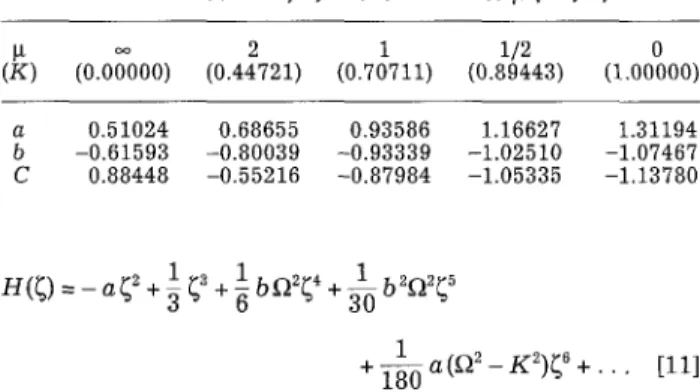
Vol. 139, No. 8, A u g u s t 1992 9 The Electrochemical Society, Inc. Table I. Values of a, b, and C at various ~ (=~/K).
(K) (0.0o0001 (0.44721) (0.70711) (0.89443) (1.00000)
Z
Fig. I. The rotating disk in a uniform flow field with the uniform approaching velocity U. t r a n s f e r of a t w o - p h a s e flow s y s t e m a t a r o t a t i n g d i s k w i t h a n e x t e r n a l f o r c e d c o n v e c t i o n .
Theoretical
T h e flow s y s t e m c o n s i d e r e d h e r e is a u n i f o r m , n o r m a l , l a m i n a r f o r c e d flow of a n i n c o m p r e s s i b l e f l u i d a g a i n s t a r o t a t i n g d i s k of i n f i n i t e r a d i u s as i n d i c a t e d i n Fig. 1. If t h e flow is a x i a l l y s y m m e t r i c a l , u n d e r s t e a d y s t a t e , t h e g o v e r n - i n g N a v i e r - S t o k e s e q u a t i o n m a y b e r e d u c e d to a set of o r d i - n a r y d i f f e r e n t i a l e q u a t i o n s b y i n t r o d u c i n g t h e f o l l o w i n g v a r i a b l e s 23 u = ;LrF(~) v = o)rG(~) w = (vX)I/2H(~) [1] a n d = ( k 2 + o~2) 1/2 ~ = (X/v)l/2z [2] w h e r e ~ is a d i m e n s i o n l e s s d i s t a n c e f r o m t h e d i s k s u r f a c e , a n d k is a h y d r o d y n a m i c c o n s t a n t w h i c h i n d i c a t e s t h e i n - t e n s i t y of t h e f o r c e d flow. T h e d e f i n i t i o n of k w i l l b e r e l a t e d to t h e f r e e - s t r e a m v e l o c i t y U i n a l a t e r s e c t i o n (see Eq. 26). O t h e r v a r i a b l e s a r e d e f i n e d i n t h e l i s t of s y m b o l s . T h e e q u a - t i o n s of c o n t i n u i t y a n d m o t i o n b e c o m e c o n t i n u i t y H ' + 2 F = 0 [3] m o t i o n F " - H F ' = F 2 - ~ 2 G 2 - K 2 [4] G " - H G " - 2 F G = 0 [5] T h e b o u n d a r y c o n d i t i o n s a f t e r t h e a b o v e t r a n s f o r m a t i o n a r e a t and at 4 = 0 F = H = O G = I [6] ~ --> ~ F = K G = 0 [7] w h e r e F~ = 0)/;% K = k / E , a n d ~2 + K 2 = 1. F o r v e r y l a r g e ~ ( f a r f r o m t h e s u r f a c e ) , H w i l l a p p r o a c h H - - 2 K ~ - C [8] w h e r e C is a flow c o n s t a n t w h i c h n e e d s to b e d e t e r m i n e d i n t h e n u m e r i c a l c o m p u t a t i o n to s a t i s f y Eq. 3-5 T h e d i m e n s i o n l e s s v e l o c i t i e s , F, G, H c a n b e e x p a n d e d f o r s m a l l ~ i n s e r i e s f o r m as 1 2 l b ~ 2 ~ l b 2 ~ 2 ~ 4 F ( ~ ) = a ~ - ~ ( - ~ + . . . [9] 1 3 + l ( a b 1)~ 4+ [10] G ( ~ ) = l + b ~ + ~ a ~ - . . . a 0.51024 0.68655 0.93586 1.16627 1.31194 b -0.61593 -0.80039 -0.93339 -1.02510 -1.07467 C 0.88448 -0.55216 -0.87984 -1.05335 -1.13780 1 ~ 1 31 0 H ( ~ ) = - a ~ 2 + ~ + ~ b F ~ 2 ~ + b 2s 5 1 2 + ~ a ( ~ - K 2 ) ~ 8 + . . . [11] Y e n a n d W a n g 29 c o m p u t e d t h e v e l o c i t i e s b y t h e m e t h o d of o r t h o g o n a l c o l l o c a t i o n s u g g e s t e d b y C a b a n a n d C h a p - m a n 29. T h e r e s u l t s w e r e s u m m a r i z e d i n T a b l e I. V a l u e s of a, b, a n d C w e r e c o r r e l a t e d b y t h e d i m e n s i o n l e s s h y d r o d y - n a m i c c o n s t a n t K a n d e x p r e s s e d i n a p o l y n o m i a l f o r m as a = 0.51023 - 0 . 0 3 2 4 7 K + 1 . 0 4 8 1 8 K 2 - 0 . 2 1 3 9 7 K 3 [12] b = - 0 . 6 1 5 9 2 - 0 . 1 7 7 1 2 K - 0 . 9 0 8 5 9 K 2 + 1 . 0 2 6 3 3 K 3 - 0 . 4 0 0 9 4 K 4 [13] C = 0.88447 - 7 . 1 7 8 2 6 K + 2 0 . 6 3 8 1 4 K 2 - 4 9 . 4 8 3 0 5 K ~ + 7 4 . 0 3 4 7 9 K 4 - 5 8 . 1 3 3 1 6 K ~ + 1 8 . 1 0 5 0 3 K 6 [14] T h e a b o v e e q u a t i o n s a r e h a n d y i n c a l c u l a t i n g a, b, a n d C f o r v a r i o u s v a l u e s of t h e d i m e n s i o n l e s s f o r c e d - f l o w c o n s t a n t K ; t h e s t a n d a r d d e v i a t i o n s a r e 0.00098 f o r a, 0.00087 f o r b, a n d 0.0042 f o r C, r e s p e c t i v e l y . If t h e d i s k is i n f i n i t e l y l a r g e a n d t h e i n t e r r a c i a l c o n c e n - t r a t i o n is u n i f o r m , t h e c o n c e n t r a t i o n profile is i n d e p e n d e n t of t h e r a n d 0 d i r e c t i o n s , a n d t h e c o n v e c t i v e d i f f u s i o n e q u a - t i o n i n d i m e n s i o n l e s s f o r m a t s t e a d y s t a t e b e c o m e s 0 " - S c H O ' = 0 [ 1 5 ] w i t h t h e b o u n d a r y c o n d i t i o n s a t = 0 O = 0 [16] at ~ ---> ~ O = l w h e r e Sc is t h e S c h m i d t n u m b e r , v / D i , a n d O r e p r e s e n t s t h e d i m e n s i o n l e s s c o n c e n t r a t i o n . T h e S h e r w o o d n u m b e r f o r m a s s t r a n s f e r is e x p r e s s e d as S h --- ~ = O'(O) [17] 0.9 0.8 o C/~ 0.7 030.6
0.5
0.0
0.85002
for
0.62048
for
flow
~
b y arotating
/ / / /
disk/ / / /
SO
q ~ - ~ e / / c tooo / d too e I0 I i I i r i I t r 0.2 0.4 0.6 0.8 1.0K
Fig. 2. Dimensionless mass-transfer factor vs. the dimensionless hydrodynamic strength for a rotating disk with an external forced flow at various Schmidt numbers.
J. Electrochem. Soc., Vol. 139, No. 8, August 1992 9 The Electrochemical Society, Inc.
2233
Table II. Comparison of the asymptotic value with the complete solution of the dimensionless moss-transfer factor for 5r _> 1.
ShSc-]/3
p = 0 ~ = 1 ~ = 2 ~ = ~
(K = 1.000) (g = 0.707) (K = 0.894) (K : 0.000)
Sc Eq. 19 Complete Eq. 19 Complete Eq. 19 Complete Eq. 19 Complete
1000 0.8427 0.8427 0.7494 0.7494 0.6713 0.6713 0.6016 0,6016 100 0.8336 0.8338 0.7378 0.7378 0.6555 0.6555 0.5789 0.5789 10 0.8132 0.8133 0.7127 0.7126 0.6225 0.6223 0.5266 0.5264 5 0.8024 0.8025 0.7004 0.7003 0.6071 0.6069 0.4995 0.4990 2 0.7823 0.7828 0.6790 0.6791 0.5821 0.5814 0.4506 0.4486 1 0.7607 0.7622 0.6575 0.6582 0.5596 0.5577 0.4007 0.3963
where Sh involves k to provide the characteristic length. (9'(0) can be obtained by integrating Eq. 22 w i t h the given boundary conditions as
1
O'(O)= foexp {Scf:
[18]
The complete solution for Sherwood n u m b e r was found by numerical integration. The resulting dimensionless mass-transfer factor S h / S c ~/3 as a function of the forced- flow strength K at various Schmidt numbers is shown in Fig. 2.
Asymptotic solution of mass transfer.--Equation
11 is substituted into Eq. 18, and part of the integrand in Eq. 18 is expanded in p o w e r series of Sc, the Sherwood n u m b e r is formulated as 9'2m3~Sel/3
Sh - f l +f2S c-u~ +f3Sc 2/3 + f4Sc-1 + f5Sc-4/3 + . . . [19] where1
1 P - V 7 (-h
/ l = 3 g ' F ( 1 ) =3
\a]
\3)1
f3 = ~ g,(g3 + g~)
1 140g~)F(1) f4 = 729 gl(108g4 + 252g2g3 + 1 f~ = 2~-87 g11810g5 + 1080(g~ + 2g2g4) + 3960g~g, + 1540g4]F(2) and [20]g,=
g2=12\a /
g 3 = ~ btl2
1b2~-12
(3) 2g5 = ~ a ( t l 2 - K 2 ) ( 3 )
v3
[21] g4 = l--~Thus, the values of f~ and g, can be estimated for any set of flow constants a and b, which depend on the forced-flow strength K and are estimated according to Eq. 12-14 or the numerical computation.
The dimensionless mass-transfer factor S h / S c u3 calcu- lated by Eq. 19 and the complete solution are listed in Table II. The complete solution is computed directly from Eq. 18. It is shown that the values predicted by the asymp- totic formula, Eq.19 can be valid down to Sc = 1. If the Schmidt n u m b e r is large enough, the velocity function in the concentration boundary layer may be a p p r o x i m a t e d as - a ~ 2, and Eq. 19 may be further simplified as
Sh = 0.7765aU 3 [22]
S e 1/3
For the flow induced purely by a rotating disk, Sh/Sc 1/3 is 0.62048 calculated w i t h a = 0.51023 and the above e q u a - tion, which shows good agreement with the ones presented
in the cited literature3< Practically, the Schmidt number is on the order of 1000 for diffusion in liquids, and Eq. 22 overestimates the mass transfer even at Sc = 1000. The error at Sc = 1000 is about 3% for the pure rotating-disk flow (K = 0) and 0.9% for the axisymmetrical stagnation flow
(K = 1).
Experimental
Although the rotating disks used in the experiment were finite, the radii of the disks were considered very large w h e n compared w i t h the boundary-layer thickness of ve- locity or concentration. The flow can be treated as that caused by an infinite disk. Similarly, the radial diffusion is usually neglected due to the thinness of the diffusion layer compared w i t h the radius of the electrode 32. In addition, the side wall of the electrolytic cell was set five times larger t h a n the diameter of the disk to avoid the effect from enclo- sure geometry. In order to m a t c h the conditions considered in the theoretical analysis, we employed a rotating disk of which the radius (ro = 0.666 cm) was smaller than the radius of the nozzle (rn = 0.8 cm). The relative size of nozzle to disk m a k e s the experimental condition closer to a u n i f o r m flow a p p r o a c h i n g to a finite disk so that the value of flow con- stant k can be determined. For comparison, w e also e m - ployed another rotating disk of 'which the radius (ro = 0.9 cm) w a s larger than that of the nozzle. This electrode g e o m e t r y is usually used in the investigation of i m p i n g i n g jet electrode. T h e determination of the h y d r o d y n a m i c strength k d e p e n d s on the g e o m e t r y of the nozzle, the di- mensionless nozzle height, a n d the exit flow condition, so a n u m b e r of correlations are available 2~ Besides the t w o dif- ferent disks w e r e used in the m e a s u r e m e n t s , the effect of the nozzle height on the mass-transfer rates w a s also d e m o n s t r a t e d in our experiments.
T h e electrolyte w a s c o m p o s e d of 2 m M p o t a s s i u m ferri- cyanide, 2 m M p o t a s s i u m ferroeyanide, a n d 0 . 2 M s o d i u m sulfate. T h e viscosity a n d density of the solution at 25~ w e r e d e t e r m i n e d to be 0.963 cp a n d 1.028 g / e m 3, respec- tively. Analytical grade chemicals ( M e r c k Co.) a n d d o u b l y distilled w a t e r w e r e used throughout. T h e temperature in all experiments w a s controlled at 25 +_ 0.1~ Nitrogen gas w a s b u b b l e d t h r o u g h the solution for at least 2 h before each e x p e r i m e n t a n d kept passing over it during the run.
The working electrode was a p l a t i n u m disk of 0.457 cm in diameter embedded in a Teflon rod either 1.333 or 1.8 cm in diameter. The electrode was first polished w i t h 0.05 lim alumina on a microclot h (Ecomet, Buehler) to a mirror-like finish. Then, it was treated electrochemically in 0,5M H2SO4 according to the method suggested by Gileadi
etal. ~.
The potential was set at 1.8 Vvs.
SCE for 10 s to oxidize impurities on the electrode surface and changed to 1.2 V for 30 s to remove oxygen formed at the higher poten- tial. Then the oxides formed at the electrode surface in the previous steps were reduced cathodically by setting the po- tential at 0.05 V. This procedure was repeated five times.In our experiments, the reduction of ferricyanide ion at the working electrode was used for limiting-current meas- urements. The current was obtained by scanning the poten- tial from 0.3 V to -0.4 V
vs.
SCE w i t h a scan rate 5 mV/s in the negative direction, which yielded current plateaus al- most identical to the current obtained at the fixed potential2234
J. Electrochem. Soc.,
Vol. 139, No. 8, August 1992 9
The Electrochemical Society,
Inc.
l 0.2 # 0.3 m A 2500 R P M r -0.2 f 0.2 /600 900 0.1 400 S c a n d i r e c L i o n 0 . 0 ~ i 0 E vs. S C E (V) - O AFig. 3. Voltammograms at rotating-disk electrode for the reduction
of Fe(CN)6 3.
-0.3 V. A n X - Y r e c o r d e r (Yew 3086) w a s c o n n e c t e d to t h e p o t e n t i o s t a t / g a l v a n o s t a t (PAR M o d e l 273) to r e c o r d t h e c u r r e n t - v o l t a g e curves. T h e e x p e r i m e n t a l r e s u l t s of t h e p o - l a r i z a t i o n c u r v e s a r e s h o w n in Fig. 3. As t h e a p p l i e d v o l t a g e is i n c r e a s e d , t h e c u r r e n t is first increased, a n d t h e n l e v e l e d off to f o r m a p l a t e a u . T h e r e s e e m e d to be a slight u p w a r d slope f o r t h e s e p o l a r i z a t i o n c u r v e s u n d e r v a r i o u s r o t a t i n g speeds. It w a s a t t r i b u t e d to t h e b a c k g r o u n d c u r r e n t g e n e r - a t e d d u r i n g s c a n as c a n be i n d i c a t e d in t h e p o l a r i z a t i o n c u r v e of 0.2M Na2SO4 b l a n k solution. H o w e v e r , t h e b a c k - g r o u n d c u r r e n t w a s so s m a l l t h a t t h e c u r r e n t p l a t e a u s c o u l d be t a k e n as t h e l i m i t i n g c u r r e n t for t h e r e d u c t i o n of ferricyanide. T h e diffusion coefficient of ferricyanide ion can be obtained f r o m the relation b e t w e e n limiting cur- rents a n d rotating speeds.T h e e x p e r i m e n t a l setup u s e d to d e t e r m i n e the m a s s - transfer coefficient k m is s h o w n in Fig. 4. W h e r e there w e r e
,
"~FLOW
I I
/DAMPER
I _ I ROTAM ETER
GLoB , .2_._
V NT
Z~ VALVE
CJ
TO
THERMOSTAT
.-),,-PUMP
SOLUTION
TANK
Fig. 4. The experimental setup for mass transfer at the forced-con-
vective rotating-disk electrode.
ROTATING
ELECTRODE
DISK t
I
J
ELE TROLYTE
EXIT
(STAINLESS STEEL)
Fig. 5. The configuration of the electrolytic cell.
t w o r o t a m e t e r s , one w a s u s e d for flow rates b e t w e e n 0.5 a n d 4 liter/rain, a n d t h e o t h e r w a s u s e d for flow rates g r e a t e r t h a n 4 liter/rain. A flow d a m p e r d o w n s t r e a m of the r o t a m e t e r s w a s u s e d to e l i m i n a t e a n y d i s t u r b a n c e in t h e e l e c t r o l y t e flow r a t e a n d to m a k e t h e v e l o c i t y profile m o r e u n i f o r m b e f o r e it e n t e r e d i n t o t h e i m p i n g i n g jet. In t h e e l e c t r o l y t i c cell (see Fig. 5), an acrylic t u b e w i t h an inside d i a m e t e r of 16 m m l o c a t e d in t h e c e n t e r of t h e b o t t o m p l a t e w a s u s e d as a nozzle, a n d t h e n o z z l e - d i s k d i s t a n c e was 15 mm. A s t a i n l e s s - s t e e l t u b e of t h e s a m e d i a m e t e r (7 cm in length) s c r e w e d to t h e acrylic t u b e s e r v e d as c o u n t e r e l e c - trode. The l i m i t i n g c u r r e n t s w e r e m e a s u r e d by s e t t i n g t h e p o t e n t i a l at -0.3 Vvs.
SCE. A t this a p p l i e d voltage, it has b e e n a s c e r t a i n e d t h a t all t h e c u r r e n t s w e r e u n d e r m a s s - t r a n s f e r c o n t r o l in o u r e x p e r i m e n t a l ranges. The c u r r e n t was m e a s u r e d for e a c h flow r a t e at several r o t a t i o n speeds. The c u r r e n t s w e r e s a m p l e d at a r a t e of 0.01 s p e r s a m p l i n g point, a n d t h e a v e r a g e v a l u e of one h u n d r e d samples w a s t a k e n as one d a t a p o i n t for current. F r o m t h e r e l a t i o n b e - t w e e n t h e l i m i t i n g c u r r e n t d e n s i t y a n d t h e i o n flux, t h e m a s s - t r a n s f e r coefficient c a n be easily c a l c u l a t e d ,i.e.
k~ - n ; C i b -[23] The l i m i t i n g c u r r e n t s u s e d for t h e d e t e r m i n a t i o n of t h e m a s s - t r a n s f e r coefficient k~ w e r e f o u n d to f l u c t u a t e d u r i n g t h e m e a s u r e m e n t s . T h e f l u c t u a t i o n w a s s m a l l w h e n the flow in t h e n o z z l e w a s l a m i n a r a n d b e c a m e m o r e o b v i o u s w h e n t h e flow w a s t u r b u l e n t . In general, it w a s a b o u t 2% of t h e a v e r a g e l i m i t i n g current. The l i m i t i n g c u r r e n t s w e r e a v e r - a g e d to g i v e a v a l u e for c a l c u l a t i o n of t h e m a s s - t r a n s f e r coefficient.
Results and Discussion
Diffusion coefficient of ferricyanide.--Under
t h e l i m i t - i n g - c u r r e n t condition, a m o d i f i e d L e v i c h ' s e q u a t i o n for t h e p u r e r o t a t i n g disk flow can be d e d u c e d f r o m Eq. 30 w i t h K = 0 a n d e x p r e s s e d as l/2 1/2 2/30.62048nFDio~
v Sc- Ci,b il = 1 + 0.2980Sc -1/~ + 0.1451Sc -2/~ + 0.0702Sc -1 + 0.0352Sc -~/3 [24] w h e r e il is t h e l i m i t i n g c u r r e n t d e n s i t y in A / c m 2. E q u a - t i o n 24 is s i m i l a r to t h e one p r e s e n t e d b y N e w m a n ~1. TheJ. Electrochem. Soc.,
Vol. 139, No. 8, August 1992 9 The Electrochemical Society, Inc. 2235 1.4 1.2 1.0 r0.8
0.6v
0.4 0.2 0.0 a n d 2ram Fe(CN)~ ~/
ak 25~0 i ~ i i I i i i i I i i i t I i ~ i i 5 10 15, / 2 , (rad/s)t/2
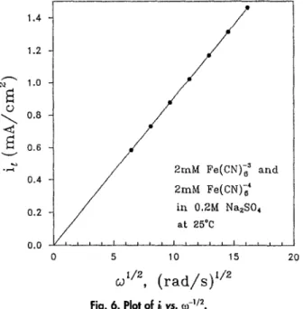
Fig. 6. Plot of ~ vs.~-~/2.
20a b o v e expression is m u c h better than the Levich equation, since the latter overestimates S h b y 3 % even at Sc = I000. T h e diffusion coefficient can be d e t e r m i n e d f r o m the de- p e n d e n c e of the limiting current density ii o n the square root of the rotating speed o Iz. T h e diffusion coefficient of ferricyanide ion w a s estimated b y iterations according to Eq. 24 f r o m t h e s l o p e of t h e b e s t f i t t e d l i n e of il vs. 0) 1/2, as s h o w n i n Fig. 6. T h e v a l u e is 6.68 • 10 -6 cm2/s, w h i c h is i n g o o d a g r e e m e n t w i t h t h e l i t e r a t u r e v a l u e s 2~ So t h e S c h m i d t n u m b e r f o r f e r r i c y a n i d e i n 0.2M Na2SO4 s o l u t i o n a t 25~ is 1402. E v a l u a t i o n of h y d r o d y n a m i c constant, k . - - T h e r a d i a l v e l o c i t y a l o n g t h e d i s k s u r f a c e f o r a c i r c u l a r d i s k of r a d i u s ro i n a u n i f o r m flow c a n b e e x p r e s s e d as 3~ 2 U r u - n rorl_/r~2]l/2L / I / [25] \~o/ J w h i c h c o u l d b e d e r i v e d f r o m t h e p o t e n t i a l t h e o r y . H e r e , U is t h e f r e e - s t r e a m v e l o c i t y of t h e u n i f o r m flow. A c c o r d i n g to H o m m a n a x i s y m m e t r i c s t a g n a t i o n flow, t h e r a d i a l v e - l o c i t y f o r a x i s y m m e t r i c s t a g n a t i o n flow is g i v e n as u = k r 36. T h e r e l a t i o n is v a l i d n o m a t t e r w h e t h e r t h e flow a t t h e n o z z l e e x i t is l a m i n a r or turbulent2% So t h e h y d r o d y n a m i c c o n s t a n t k is r e l a t e d to t h e v e l o c i t y of t h e f o r c e d flow U as 2 U 1 k - [26]
r o l l _ (r/2]1/2
\~ool J If r/ro is s m a l l e n o u g h , w h i c h m e a n s i n t h e r e g i o n n e a r t h e c e n t e r of t h e disk, k m a y b e e x p r e s s e d as k = - - 2 U [27] ~ro If t h e d i s k e l e c t r o d e e m b e d d e d i n t h e i n e r t i n s u l a t o r is s m a l l e n o u g h , k c a n b e e v a l u a t e d f r o m t h e a b o v e e q u a t i o n . B e c a u s e t h e r a t i o of t h e d i s k e l e c t r o d e to the- s m a l l d i s k u s e d in the e x p e r i m e n t w a s re/ro = 0.228/0.666 = 0.343, it s e e m e d m o r e r e a s o n a b l e to t a k e t h e a v e r a g e v a l u e of k f r o m Eq. 26. T h e r e s u l t is = rore sin ~ ro • ( ~ o U) [28] F o r rJro = 0.343, k = 1.02 • (2/nro U). T h e r e f o r e , e v e n t h o u ~ h rJro is as l a r g e as 0.343, t h e d i f f e r e n c e b e t w e e n k a n d ~ i i so n l y 2%. I n o u r c a l c u l a t i o n , k w a s u s e d i n s t e a d of k.
Mass transfer at the forced-convective rotating and sta- tionary disk e l e c t r o d e s . - - T h e d i m e n s i o n l e s s m a s s - t r a n s f e r
f a c t o r s m e a s u r e d i n t h i s e x p e r i m e n t a r e l i s t e d i n T a b l e HI
Table IlL Experimental data.
U k to il Sh/Scl/~
(cm/s) (l/s) (rad/s) p = 0Y~/k (mA/cm 2) Exptl. Theory 5.803 5.657 0.000 0.000 0.355 1.000 0.843 10.472 1.851 0.386 0.750 0.680 20.944 3.702 0.458 0.660 0.629 31.416 5.553 0.534 0.634 0.615 41.888 7.404 (I.602 0.621 0.610 52.360 9.256 0.666 0.616 0.607 62.832 11.107 0.725 0.612 0.606 94.248 16.660 0.877 0.605 0.604 9.118 8.890 0.000 0.000 0.442 0.995 0.843 10.472 1.178 0.454 0.822 0.732 20.944 2.356 0.499 0.702 0.658 31.416 3.534 (}.562 0.660 0.631 41.888 4.712 0.621 0.637 0.619 52.360 5.890 0.682 0.628 0.614 62.832 7.068 0.737 0.621 0.610 73.304 8.246 0.792 0.618 0.608 16.579 16.163 0.000 0.000 0.579 0.965 0.843 10.472 0.648 0.587 0.897 0.793 20.944 1.296 0.609 0.794 0.720 31.416 1.944 0.640 0.722 0.675 41.887 2.592 0.688 0.689 0.650 62.832 3.887 0.780 0.649 0.626 83.776 5.183 0.865 0.628 0.617 104.720 6.479 0.962 0.627 0.612 24.868 24.245 0.000 0.000 0.704 0.958 0.843 10.472 0.432 40.694 0.906 0.818 26.180 1.080 ,0.722 0.810 0.742 41.888 1.728 0.745 0.718 0.688 62.832 2.592 0.822 0.672 0.650 83.776 3.455 0.904 0.649 0.632 104.720 4.319 0.987 0.638 0.622 125.664 5.183 1.060 0.628 0.617 41.447 40.408 0.000 0.000 0.834 0.881 0.843 10.472 0.259 0.826 0.857 0.833 26.180 0.648 0.839 0.811 0.793 41.888 1.037 0.852 0.749 0.746 78.540 1.943 0.950 0.678 0.675 104.720 2.592 1.023 0.648 0.650 130.900 3.239 1.109 0.635 0.635 167.552 4.147 1.212 0.619 0.624 62.170 60.612 0.000 0.000 0.979 0.844 0.843 10.472 0.173 0.980 0.838 0.839 26.180 0.432 0.987 0.815 0.818 41.888 0.691 1.003 0.783 0.787 78.540 1.296 1.051 0.708 0.720 104.720 1.728 1.114 0.679 0.688 130.900 2.160 1.170 0.653 0.665 167.552 2.764 1.267 0.637 0.645
a n d p l o t t e d i n Fig. 7. T h e c o m p l e t e s o l u t i o n (solid line) is c o m p u t e d b y t h e n u m e r i c a l i n t e g r a t i o n of t h e c o n v e c t i v e - d i f f u s i o n e q u a t i o n , Eq. 18, a n d t h e a p p r o x i m a t e s o l u t i o n 1
t
S c = / 4 0 2 |l .
Re
0.9 "~ * + 9 9 1 J . • 1 5 5 8 ~, , 2 8 3 2 0.8 ~ x * 4 2 4 9 ~ , * 9 7 0 8 1 O - ~ 9 1 0 6 2 2+
~k\o* C o m p l e t e s o l u t l o n LQ 0.7 A \ \ x . - - - A p p r o x i m a t e v a l u e ,='~ .~ calculated by Eq.[221 0.6 0 . 5 , J i I i , i ! , , , I I I ~ I I I I 0 2 4 6 8 10=O/K
1/3
Fig. 7. Sh/Sc vs. ~ under various Reynolds numbers of lhe forced R O W .
2236 J. E l e c t r o c h e m .
Soc., Col. 139, No. 8,
August 1992 9 The Electrochemical Society, Inc. 1.0 S c = 1 4 0 2 o.9 R e + 991 x 1558 \ . * 2 8 3 2 0 . 8\
(9 ~d~ 0.7 ~ T h e o r e t i c a l 0.6 0.5 , I a I n I , I t r r [ r t I I r t , 0 2 4 6 8 10Fig. 8. Sh/Sc '/s vs. p for laminar flow in which the velocity used to calculate/c was corrected according to Eq. 29.
(dashed line) is calculated according to Eq. 22, which is exact for very large Schmidt numbers. By comparing the experimental data with the complete solution, it is found that there is a satisfactory agreement if the flow in the nozzle is t u r b u l e n t (Re > 4000; the Reynolds n u m b e r is based on the diameter of the circular nozzle, i.e., Udn/v).
But the agreement does not seem good, if the flow in the nozzle is l a m i n a r (Re < 2100), especially when fa/K is small. As we know, the velocity profile is parabolic in the nozzle for l a m i n a r flow. The velocity near the central line is greater t h a n the average_velocity. Therefore, the calculated hydrodynamic strength k based on the average velocity U will be smaller t h a n that based on the actual velocity. In order to account for the deviations caused by the k values in the l a m i n e r flow region, the velocity profile in the nozzle was considered a n d E should be corrected as
U * = 4 r 1 - ~ dr/r~=l.3O6g [291
where ro = 0.666 cm, a n d U* represents the effective free- stream velocity from the nozzle. The dimensionless mass- transfer factors after replacing U by U* in the calculation of k is replotted a n d shown in Fig. 8. As can be seen in Fig. 8, the measured mass-transfer coefficients are i n good accordance with the theoretical values. For t u r b u l e n t flow in a smooth circular tube, the velocity profile over the cross section is much more uniform t h a n that i n l a m i n a r flow. So it is .not necessary to use Eq. 29 to correct k for t u r b u l e n t flow.
Figure 9 is the plot of Sh/Sc 1/3 vs. the relative rotating strength ~t for the theoretical values and the experimental results obtained by the larger disk (ro = 0.9 cm). The disk radius was used for calculating k a n d Sh. It is found that the deviations from theoretical values are more obvious t h a n those obtained previously by the smaller disk (ro = 0.666 cm). The discrepancy reveals the evaluation of k by use of the disk radius is inappropriate if the disk radius becomes larger t h a n the nozzle radius. I n this case, how- ever, the disk would be supposed to have the same radius as the nozzle, a n d the value of k could be determined accord- ingly. The results with this correction are replotted i n Fig. 10, and the agreement is shown to be improved. The same difficulty in estimating the hydrodynamic strength k had been encountered in the study of Chin and Tsang 21. The electrode used in their experiments was m o u n t e d i n a Plex- iglas plate, the diameter of which was larger than the di- ameter of the nozzle. Although they presented a theoretical equation as Eq. 22 with a = 1.3119 for predicting mass- transfer rates, the experimental data were not compared
1.2 0 1.1 1.0 0.9 0.8 0.7 0.6 an~ Sc=1402 Re + 991 x 1558 , 2 8 3 2 9 4 2 4 9 9 7 0 8 1
N
x *•
T h e o r e t i c a l ~ . Z + x 0 . 5 I I i I i i t I r i I I i , r l i i 0 2 4 6 8 10/,=f}/K
Fig. 9. Sh/Sc '/a vs. ~t for various Reynolds numbers of the forced flow. The ex_l~rimental data were obtained by the larger disk, ro = 0.9 cm, and k was calculai~ on the basis of disk radius.
with their theoretical values. Instead, the experimental data were correlated as two empirical equations. One is suitable for l a m i n a r flow, a n d the other for t u r b u l e n t flow. We also applied our approach to determine the hydrody- namic strength k of the experimental results by Chin a n d Tsang 2~ The data were taken directly from their paper 2~ a n d the results for the stationary electrode impinged by a jet are shown in Fig. 11. The mass-transfer factor Sh/Se 1/3 is i n d e p e n d e n t of the Reynolds n u m b e r in the nozzle, be- cause the Sherwood n u m b e r Sh involves the mixed flow strength X which can be related to the hydrodynamic strength of the forced flow from the nozzle. I n general, the experimental data fall w i t h i n 10% of the theoretical pre- diction, as well as their correlations could predict.
Effect of nozzle height on mass transfer.--Equation 29 is based on the assumption that the velocity distribution near the exit of the nozzle is the same as that in the feed tube. As a rule, the core length of the jet extends 4.7 to 7.7 nozzle
1.2 1.1 1.o 0.9 o.B U] 0.7 0.6 Sc=1402 Re + 991 x 1 5 5 8 , 2 8 3 2 9 4 2 4 9 9 7 0 8 1 o * T h e o r e t i c a l 0 . 5 i r i I r f l I r p f I r i i I = i r 0 2 4 6 8 10
/,=C2/K
Fig. 10. Sh/Sc 1/3 vs. M for various Reynolds numbers of the forced
flow. The exp_erimental data were obtained by the larger disk, ro = 0.9 cm, and ~ was calculated on the basis of the nozzle radius.
J. Electrochem. Soc., Vol. 139, No. 8, August 1992 9 The Electrochemical Society, Inc. 2237 1.6 1.2 eo .-4 0 5Q 0.8 0Q 0.4 0.0 9 O 0 0 0 9 9 O 0 0 0 0 0 0 0 0 T h e o r e t i c a l
o Chin & Tsang (21) 9 T h i s w o r k
L , , , i t ,
o .... 2'5 .... 5'o' '7's' "1oo"
'l g
Ret/2
Fig. 11. Comparison between the results of this work and Chin and Tsang 2~ for the stationary electrode impinged by a jet. The data in Fig. 10 are used.
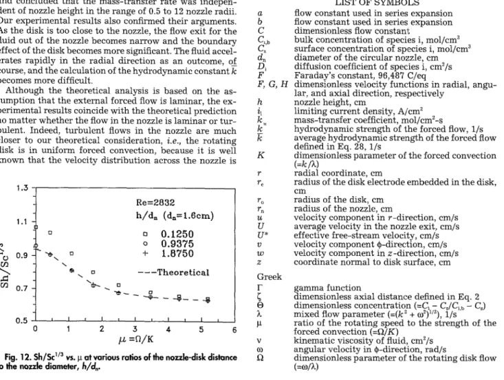
diameters 37. Thus, if the distance b e t w e e n the disk a n d the nozzle is not too far, Eq. 29 is suitable for calculating U*. T h r e e distances (h/d~ = 0.125, 0.9375, 1.875) w e r e t a k e n for m e a s u r e m e n t s in our experiments, a n d one of the results is s h o w n in Fig. 12. T h e dimensionless mass-transfer factor, S h / S c ~/3, for b o t h h/d~ = 0.9375 a n d 1.875 w a s f o u n d to be almost the same. In fact, there w e r e n o differences observed over our experimental ranges of rotating speed of the disk a n d flow rate of the i m p i n g i n g jet. B u t in the case of h/d, = 0.125, the mass-transfer factor w a s obviously higher t h a n those m e a s u r e d in the other two'cases. T h e difference be- c a m e smaller as the rotating s p e e d increased, b e c a u s e the mass-transfer rate for a forced-convective rotating disk w a s d o m i n a t e d b y the rotating speed of the disk w h e n the relative strength ratio of rotating speed to external convec- tion w a s high. Scholtz a n d Trass ~ studied the effect of noz- zle height o n the mass-transfer rate f r o m the i m p i n g i n g jet, a n d c o n c l u d e d that the mass-transfer rate w a s i n d e p e n - dent of nozzle height in the range of 0.5 to 12 nozzle radii. O u r experimental results also confirmed their arguments. A s the disk is too close to the nozzle, the flow exit for the fluid out of the nozzle b e c o m e s n a r r o w a n d the b o u n d a r y effect of the disk b e c o m e s m o r e significant. T h e fluid accel- erates rapidly in the radial direction as a n o u t c o m e , of course, a n d the calculation of the h y d r o d y n a m i c constant k b e c o m e s m o r e difficult.
A l t h o u g h the theoretical analysis is b a s e d o n the as- s u m p t i o n that the external forced flow is laminar, the ex- perimental results coincide w i t h the theoretical prediction n o m a t t e r w h e t h e r the flow in the nozzle is l a m i n a r or tur- bulent. Indeed, turbulent flows in the nozzle are m u c h closer to our theoretical consideration, i.e., the rotating disk is in u n i f o r m forced convection, b e c a u s e it is well k n o w n that the velocity distribution across the nozzle is
1.5 1.1 " 0 0.9 u] o.7 Re=2832 h / d ~ (d~= 1.6cra) = D 0 . 1 2 5 0 o 0 . 9 3 7 5 - ~ \ o + 1 . 8 7 5 0 a - - - T h e o r e t i c a l " ~ ' ~ - ~ _ _ . ~ _ _ . ~ 0 . 5 l I v I i I i I I I i 0 1 2 3 4 5 6 /a. = ~ / K
Fig. 12. Sh/Sc 1/3 vs. ~ at various ratios of the nozzle-disk distonce to
the
nozzle diameter, h/d,.more uniform u n d e r t u r b u l e n t flow. The variation of hy- drodynamic constant k with radius has been considered in this study b u t the dsitribution of mass-transfer rates in t h e
radial direction has not been investigated yet. For the elec- trode used in the experiment, the variation of the hydrody- namic constant k along the disk-electrode surface is so small that the mass-transfer distribution at the forced- convective rotating-disk electrode can be regarded as u n i - form.
Conclusions
The mass transfer for a rotating disk imposed by a n ex- ternal forced flow has been studied in this work. In addition to the theoretical analysis, the mass-transfer rates were measured by the electrochemical method. A comparison was made b e t w e e n t h e experimental and theoretical val- ues. The corresponding mass-transfer rates were formu- lated from integrating the convective diffusion equation after the velocities were solved. An asymptotic expression has been obtained by taking the first few terms of the veloc- ity profile, which is accurate down to Sc = 1. It has been found that the mass-transfer factors measured in the ex- periment are in good agreement with the theoretical values in the turbulent-flow region in the nozzle. For l a m i n a r flow in the nozzle, the accordance would be greatly improved if
t h e velocity distribution in the flow is taken into consider- ation.
Acknowledgment
This work was supported by the National Science Coun- cil of Taiwan, China, u n d e r Contract No. NSC 81-0402- E002-02.
Manuscript submitted Nov. 18, 1991; revised m a n u s c r i p t received April 10, 1992.
National Taiwan University assisted in meeting the publication costs of this article.
a b C d~ Di F F , G , H h il k k ~ K r re ro r~ U U U* V m z Greek F 0 k g V CO f~ LIST OF SYMBOLS
flow constant used in series expansion flow constant used in series expansion dimensionless flow constant
bulk concentration of species i, mol/cm 3 surface concentration of species i, mol/cm 3 diameter of the circular nozzle, cm diffusion coefficient of species i, cm2/s Faraday's constant, 96,487 C/eq
dimensionless velocity functions in radial, angu- lar, a n d axial direction, respectively
nozzle height, cm
limiting current density, A/cm 2 mass-transfer coefficient, mol/cm2-s
hydrodynamic strength of the forced flow, 1/s average hydrodynamic strength of the forced flow defined in Eq. 28, 1/s
dimensionless parameter of the forced convection
(=k l~)
radial coordinate, cm
radius of the disk electrode embedded in the disk, cm
radius of the disk, cm radius of the nozzle, cm
velocity component in r-direction, cm/s average velocity in the nozzle exit, cm/s effective free-stream velocity, cm/s velocity component C-direction, cm/s velocity component in z-direction, cm/s coordinate normal to disk surface, cm gamma function
dimensionless axial distance defined in Eq. 2 dimensionless concentration (=Ci- C J C i b - Cs) mixed flow parameter (=(k 2 + r 1/s
ratio of the rotating speed to the strength of t h e
forced convection (=~2/K)
kinematic viscosity of fluid, cm2/s angular velocity in ~-direction, rad/s
dimensionless parameter of the rotating disk flow
2238
J. E/ectrochem. Soc.,
Vol.
Dimensionless
Re Reynolds n u m b e r in the nozzle,
Udn/v
Sc S c h m i d t n u m b e r
(=v/Di)
Sh Sherwood n u m b e r
(=krJDi(k/V) -1/2)
R E F E R E N C E S
1. A. C. Riddford,
Adv. Electrochem. Electrochem. Eng.,
4, 47 (1966).
2. M . E . Coltrin, R. J. Kee, and G. H. Evans,
This Journal,
136, 819 (1989).
3. J. N. B. L i v i n g o o d a n d P. Hrycak, N A S A T M X - 2 7 7 8
(1973).
4. F. Giralt a n d O. Trass, Can. J. C h e m . Eng., 53, 505 (1975), ibid., 54, 148 (1976).
5. T. y o n K ~ r m ~ n , Z. A n g e w . Math. Mech., I, 244 (1921). 6. W . G. Cochran, Proc. C a m b r . Phil. Soc., 30, 365 (1934). 7. E. M . S p a r r o w a n d J. L. Gregg, J. H e a t Transfer, 82C,
294 (1960).
8. J. N e w m a n , J. Phys. Chem., 70, 1327 (1966).
9. K. T. Liu a n d W . E. Stewart, Int. J. H e a t M a s s Transfer,
15,
187 (1972).i0. C. L. Tien a n d D. T. Campbell, J. Fluid Mechanics,
17,
105 (1963).
ii. J. N e w m a n a n d L. Hsueh, Electrochim. Acta, 12, 417 (1967).
12. M. Daguenet,
Int. J. Heat Mass Transfer,
11, 1581(1968).
13. F. Kreith, J. H. Taylor, and J. P. Chong,
Trans. ASME,
J. Heat Transfer,
81, 95 (1959).14. C. M. Mohr, Jr., and J. Newman,
This Journal,
123, 1687(1976).
15. B. T. Ellison and I. Cornet,
ibid.,
118, 68 (1971). 16. M. T. Scholtz and O. Trass,AIChE J.,
16, 82 (1970). 17. M. T. Scholtz and O. Trass,ibid.,
9, 548 (1964). 18. J. Y a m a d a and H. Matsuda,J. Electroanal. Chem.,
44,189 (1973).
139, No. 8, August 1992 9 The Electrochemical Society, Inc.
19. F. Coeuret,
Chem. Eng. Sci.,
30, 1257 (1975).20. D. T. Chin and C. H. Tsang,
This Journal,
125, 1461(1978).
21. D. T. Chin and R. R. Chandran,
ibid.,
128, 1904 (1981). 22. R. C. A l k i r e and T. J. Chen,This Journal,
129, 2424(1982).
23. D. M. Hannah,
Br. Aero. Res. Comm. Rep. Memo.,
No.2772 (]947).
24. H. Sch]ichting and E. Truckenbrodt,
J. Aero. Sci.,
Readers' Forum,
18, 639 (1951).25. C. L. Tien and J. Tsuji,
Int. J. Heat Mass Transfer,
7,247(1964).
26. M. H. Lee, D. R. Jeng, and K. J. De Witt,
Trans. ASME,
J. Heat Transfer,
100, 496 (1978).27. S. S: Koong and P. L. Blackshear,
ibid.,
87,442 (1965).28. S. C. Yen and J. S. Wang,
Chem. Eng. Sci.,
In press(1991).
29. R. Caban and T. W. Chapman,
Chem. Eng. Sci.,
36,
849(1981).
30. J. Newman,
J. Phys. Chem.,
70, 1327 (1966).31. J. S. Newman,
Electrochemical Systems,
Prentice-Hall, Englewood Cliffs, NJ (1973).
32. W. H. Smyrl and J. Newman,
This Journal,
118, 1079(1971).
33. E. Gileadi, E. Kirowa-Eisner, and J. Penciner,
Interra-
cial Electrochemistry~An Experimental Approach,
A d d i s o n - W e s l e y Publishing Co., Inc., Reading, MA (1975).
34. A. J. Arvia, S. L. Marchiano, and J. J. Podesta,
Elec-
trochim. Acta,
12,
259 (1967).35. H. Lamb,
Hydrodynamics,
Dover, New York (1945).36. F. Homman,
ZAMN,
16,
153 (1936); also see H.Sch]ichting,
Boundary Layer Theory,
7th ed., pp. 95-98, McGraw-Hill, Inc., New York (1979).
37. J. W. Gauntner, J. N. B. Livingood, and P. Hrycak,
N A S A Tn
D5652 (1970).Erratum
The affiliation of Dr. Chris A. Mack, the a u t h o r of t h e Electrochemical Society L e t t e r " N e w Kinetic Model for Resist D i s s o l u t i o n " w h i c h a p p e a r e d in the A p r i l 1992 issue of t h e