Yuan Mao Huang
Professor e-mail: ymhuang@ccms.ntu.edu.twChin-Ming Wang
Research AssistantDepartment of Mechanical Engineering, National Taiwan University, Taipei, Taiwan Republic of China
Combined Methodology for
Analysis of Rotary Systems
This study develops a numerical method for analyzing the unbalanced effect of rotary systems by combining the finite element method, the transfer matrix method, the time marching numerical integration method and the Houbolt numerical method. Previous studies of the individual effects associated with the rotary inertia, gyroscopic phenom-enon, shear deformation, axial loading and internal damping on the dynamic behavior of rotary systems are all incorporated and examined in this study. The calculated transient and steady displacements of components in two systems are comparable with the avail-able data. The results show that maximum displacements occur in the transient states at some critical speeds to assure the importance for analyzing the unbalanced effect of the rotary systems. Compared with existing methods, this presently combined methodology provides a faster converging speed. In addition, this model should improve the predicted results for the transient dynamic analysis of rotary systems than those obtained from existing models. 关DOI: 10.1115/1.1385204兴
Introduction
Steady state responses are investigated in most analyses of dy-namic rotary systems. While the transient dydy-namic characteristics of the system before reaching the steady state are important, they are complicated. The transient dynamic behavior of the system has a significant effect on the steady state response of the system, especially when it operates near the critical speed or with an un-balanced force generated.
Adams 关1兴 used the Jeffcott rotor formulation and Nelson 关2兴 used the finite element method to develop models for rotary sys-tems. Dokainish关3兴 combined the finite element method and the transfer matrix method关4兴 to reduce the size of the global matrix. Kumar and Sankar关5兴 developed the discrete time transfer matrix method. Subbiah et al.关6兴 simulated the model with the Nelson and McVaugh’s finite element model关7兴 to develop a new tran-sient property transfer approach. The finite element method is an effective technique for the transient analysis. However, the de-grees of freedom and the required computer memory increase sig-nificantly when the number of elements increases. Therefore, there may be a loss in efficiency for large rotor systems. To im-prove the efficiency for analyzing the dynamic behavior of a ro-tary system, the present study developed a numerical method by combining the finite element method, the transfer matrix method, the time marching numerical integration method and the Houbolt numerical method关8兴. Furthermore, individual effects due to the rotary inertia, gyroscopic phenomenon, shear deformation, axial load and internal damping on the transient response of the system that have been analyzed by Nelson关2兴, Dokainish 关3兴, Subbiah et al.关6兴, Nelson and McVaugh 关7兴, O¨zguven and O¨zkan 关9兴, Sub-biah and Rieger关10兴, and Alam and Nelson 关11兴 were all incor-porated in the present study. It was hypothesized that this pro-posed methodology would improve calculated results with a faster converging speed than existing methods and models, especially, for large rotary systems.
Finite Element Model of Components
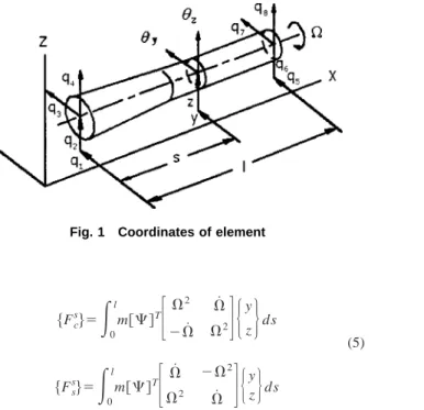
A finite element as shown in Fig. 1 has eight degrees of free-dom, qi, i⫽1,2,3, . . . 8. There are two translational displace-ments and two rotational displacedisplace-ments for each end. The
ap-proximated translational displacement and rotational displacement at any point in the element of the shaft can be expressed, respec-tively, by
再
y共s,t兲 z共s,t兲冎
⫽冋
1 0 0 2 3 0 0 4 0 1 ⫺2 0 0 3 ⫺4 0册
兵 q共t兲其 (1)再
y共s,t兲 z共s,t兲冎
⫽冋
0 ⫺1 2 0 0 ⫺3 4 0 1 0 0 2 3 0 0 4册
⫻兵q共t兲其 (2)where the distance s is measured from the left end of the point of interest 关7兴. The symbol 兵q(t)其 is the displacement vectors of nodal points at both ends of the element. The shape functions j(s) andk(s) are the static displacement modes when one end has a unit displacement and another end has zero displacement. Both shape functions are functions of the location, geometry and material properties. The centroid locations of the cross sections in elements are assumed to be a linear distribution.
Considering all of the effects of the rotary inertia, gyroscopic effect, axial loading, shear deformation and internal damping, and substituting kinetic energy, the potential energy and the virtual work due to the unbalanced force into the Hamilton’s equation yields 共关MT s兴⫹关M R s兴兲兵 q¨s其⫹共 V关KB s兴⫺⍀关Gs兴兲兵q˙s其⫹
冋
1⫹H冑
1⫹H 2关KB s兴 ⫺关KA s兴⫹冉
V⍀⫹ H冑
1⫹H2冊
关KC s兴册
兵qs其⫽兵Fs其 (3) where the coefficient matrix 关MTs兴 is the function of the mass, length and transverse shear effect, the coefficient matrices关MR
s兴 and关Gs兴 are the function of the mass, diameter, length and trans-verse shear effect, the coefficient matrices关KBs兴, 关KAs兴 and 关KCs兴 are the function of the transverse shear effect and axial loading, and the unbalanced force in an element can be expressed as
兵Fs其⫽兵Fc s 其cos⍀t⫹兵Fs s 其sin⍀t (4) where
Contributed by the Technical Committee on Vibration and Sound for publication in the JOURNAL OFVIBRATION ANDACOUSTICS. Manuscript received Nov. 1999; revised Jan. 2001. Associate Editor: C. Pierre.
兵Fc s其⫽
冕
0 l m关⌿兴T冋
⍀ 2 ⍀˙ ⫺⍀˙ ⍀2册
再
y z冎
ds (5) 兵Fs s其⫽冕
0 l m关⌿兴T冋
⍀˙ ⫺⍀ 2 ⍀2 ⍀˙册
再
y z冎
dsThe matrix of the gyroscopic effect is skew symmetric, and the other coefficient matrices are symmetric.
Similarly, considering the disk as a point mass with four de-grees of freedom and applying the Hamilton principle, the result-ing equation is 共关MT d兴⫹关M R d兴兲兵 q¨d其⫺⍀关Gd兴兵q˙d其⫽兵Fd其 (6) where 关MT d兴, 关M R
d兴 and 关Gd兴 are matrices of md , ID
d and IP
d , respectively关7兴. The unbalanced force of the disk is
兵FD其⫽兵Fc d 其cos⍀t⫹兵Fs d 其sin⍀t⫹兵Fg其 (7) where 兵Fc d其 ⫽md
冋
⍀2 ⍀˙ 0 0 ⫺⍀˙ ⍀2 0 0 0 0 0 0 0 0 0 0册
冦
yd zd 0 0冧
兵Fsd其⫽md冋
⍀˙ ⫺⍀2 0 0 ⍀2 ⍀˙2 0 0 0 0 0 0 0 0 0 0册
冦
yd zd 0 0冧
(8) 兵Fg其⫽冦
0 ⫺md g 0 0冧
The bearing is assumed to consist of four springs and four dampers as shown in Fig. 2, and the load acting on the bearing concentrated at the node is关9兴
兵Fb其⫽⫺关Cb兴兵q˙b其⫺关Kb兴兵qb其 (9) where 兵qb其⫽
再
y z冎
关Cb兴⫽冋
cy y cy z cz y czz册
(10) 关Kb兴⫽冋
ky y ky z kz y kzz册
From the Newmark method关12兴, the Wilson method 关13兴 and the Houbolt method关8兴, the angular acceleration and the angular ve-locity can be expressed, respectively, as
兵q¨共ti兲其⫽A共ti兲兵q共ti兲其⫹兵B共ti兲其 (11) and
兵q˙共ti兲其⫽D共ti兲兵q共ti兲其⫹兵E共ti兲其 (12) where the coefficients A(ti), D(ti), 兵B(t1)其and兵E(ti)其depend on the numerical integration used.
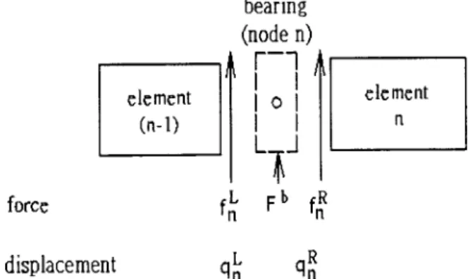
The force between the (n⫺1)th and the nth elements in the shaft is shown in Fig. 3. If the external load acting on the nth nodal point is兵Fn(ti)其, the loads acting on the right side of the (n⫺1)th element and the left side of the nth element are兵fnL(ti)其 and兵fn
R
(ti)其, respectively. The static balance equation is关14兴
兵fnR共ti兲其⫽兵Fn共ti兲其⫺兵fn L共t
i兲其 (13)
Substituting Eqs.共11兲, 共12兲 and 共13兲 into Eq. 共3兲 yields
兵un⫹1 L 共t i兲其⫽关Tn s共t i兲兴兵un L共t i兲其 (14) where兵unL⫹1其and兵un L其
are the state vectors of the right sides of the nth and the (n⫺1)th elements, and 关Tns兴 is the transfer matrix. The nth nodal point for the disk between two shaft elements is shown in Fig. 4. The external load兵Fn
d
其that is the resultant inter-action force between elements and the unbalanced force of the disk is 兵Fn d共t i兲其⫽⫺兵fn L共t i兲其⫺兵fn R共t i兲其⫹兵FD共ti兲其 (15)
Fig. 1 Coordinates of element Fig. 2 Bearing model
Substituting Eqs.共11兲, 共12兲 and 共15兲 into Eq. 共6兲 with the consis-tent property of the nodal point
兵qn L其 ⫽兵qn R其 (16) yields 兵unR共ti兲其⫽关Tn d共t i兲兴兵un L共t i兲其 (17) where兵un R其 and兵un L其
are the state vectors on the left side of the nth element and the right side of the (n⫺1)th element, and 关Tnd兴 is the transfer matrix.
The bearing between two elements of the shaft can be consid-ered as a point element as shown in Fig. 5. The equation of force balance of the bearing is
兵Fb共ti兲其⫽兵fn L共t
i兲其⫹兵fn R共t
i兲其 (18)
Substituting Eqs.共9兲, 共16兲 and 共18兲 into the equation of motion, the relationship of state vectors can be expressed as
兵un R共t i兲其⫽关Tn b共t i兲兴兵un L共t i兲其 (19) where兵un R其 and兵un L其
are the state vectors of the left side of the nth element and the right side of the (n⫺1)th element, and 关Tn
b兴 is the transfer matrix of the bearing. Applying the transfer matrix method, the relationship of state vectors for both ends of the sys-tem can be expressed as
兵umR共ti兲其⫽关Tm共ti兲兴关Tm⫺1共ti兲兴••••关T2共ti兲兴关T1共ti兲兴兵u1 L共t i兲其 ⫽关Ts y s共ti兲兴兵ul L共t i兲其 (20)
where关Ts y s兴 stands for the overall transfer matrix 关4兴. Using the Houbolt numerical integration method with the appropriate boundary condition and the quantities obtained from the previous time step as the initial condition,兵um
R
(ti)其, 兵ul L
(ti)其and the state vector at any location can be determined关8兴.
Result
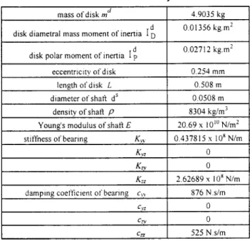
The first system analyzed is illustrated in Fig. 6 and consists of a disk at the center of a shaft that is supported by two identical nonisotropic bearings at each end. The mass of the disk is as-sumed to be concentrated at a point with an eccentricity from the disk center due to unbalance at time t⫽0. Each bearing is simu-lated by four springs and four dampers. The shaft is assumed to be uniform and flexible. The data for the system used in the analysis is obtained from Subbiah and Rieger关10兴 and shown in Table 1. The shaft is divided into eight identical elements. There are a total of 36 degrees of freedom for the system. The boundary con-dition has no load acting on either end of the shaft. The system is considered to be undamped at time t⫽0, and the resulting dis-placements are then used as the starting values for the subsequent iteration of the damped system关10兴. When the rotational speed is 40 rev/s, the system reaches the steady state within the third revo-lution. The effects of the step number for each revolution, NC, on the accuracy of result and the converging speed are studied. The maximum deviations between the calculated transient displace-ments and the data obtained by Subbiah and Rieger关10兴 for vari-ous NCare shown in Table 2. The value of NCequal to 30 is used for further analysis. The calculated transient and steady displace-ments of the disk center and the data obtained by Subbiah and Rieger关10兴 are shown in Figs. 7 and 8, respectively. The symbols y and z are the displacements in the Y and Z directions,
respec-Fig. 4 Force between disk and shaft
Fig. 5 Force between bearing and shaft
Fig. 6 Rotary system Table 1 Data of first system
Table 2 Effect ofNCon deviation of maximum transient
tively. The calculated transient displacements of the centers at the disk and bearings are shown in Fig. 9. The time required for a rotary system to reach the steady state varies for different rota-tional speeds. The maximum transient displacements at the disk center versus the rotational speed of the shaft calculated in this study, obtained from Subbiah and Rieger关10兴 and obtained from the software ANSYS are shown in Fig. 10. Similarly, the calcu-lated maximum transient displacement of the bearing center ver-sus the rotational speed of the shaft is shown in Fig. 11.
The second system used in the analysis that is similar to the system as shown in Fig. 6 is an asymmetric system. The disk is at a distance that is at the four fifth of the shaft length measured from the left end of the shaft and the bearings are orthotropic. The data of this asymmetric system obtained from Alam and Nelson 关11兴 who analyzed the steady state and transient state by using the component mode synthesis are shown in Table 3.
Both ends of the shaft are free and the shaft is divided into five elements. With the disk as a point element there are twenty four degrees of freedom for the system. The calculated maximum tran-sient displacements in the Y and Z directions versus the rotational speed of the shaft and the data obtained by Alam and Nelson关11兴 are shown in Figs. 12 and 13, respectively. The maximum steady
displacements of the disk center in the Y and Z directions versus the rotational speed and the data obtained by Alam and Nelson 关11兴 are shown in Figs. 14 and 15, respectively. When the rota-tional speed of the shaft is 1550 rad/s, with NC equal to 30 the transient displacement of the disk center is shown in Fig. 16. The system reaches the steady state within 45 revolutions, and the steady displacement of the disk center is shown in Fig. 17. The maximum displacement occurs at 0.2036 s. If the rotational speed of the shaft is 3100 rad/s, the transient displacement of the disk center with NC equal to 30 is shown in Fig. 18. The steady dis-placement of the disk center that reaches the steady state within 80 revolutions is shown in Fig. 19. The maximum displacement
Fig. 7 Transient displacement of disk center withNCÄ30
Fig. 8 Steady displacement of disk center withNCÄ30
Fig. 9 Transient displacements of centers at disk and bear-ings withNCÄ30
Fig. 10 Maximum transient displacement of disk center ver-sus rotational speed withNCÄ30
Fig. 11 Maximum transient displacement of bearing center versus rotational speed withNCÄ30
Fig. 12 Maximum transient displacement of disk center inY
direction versus rotational speed
Fig. 13 Maximum transient displacement of disk center inZ
direction versus rotational speed
Fig. 14 Maximum steady displacement of disk center inY di-rection versus rotational speed
Fig. 15 Maximum steady displacement of disk center inZ di-rection versus rotational speed
Fig. 16 Transient displacement trace of disk center at ⍀
Ä1550 radÕs
Fig. 17 Steady displacement trace of disk center at⍀Ä1550 radÕs
Fig. 18 Transient displacement of disk center at ⍀Ä3100 radÕs
occurs at 0.0162 s. If the rotational speed of the shaft is 4100 rad/s, with NC equal to 40, then the system reaches the steady state within 130 revolutions and the maximum displacement oc-curs at 0.0097 s.
Discussion
Subbiah and Rieger 关10兴 stated that the converging speed for the analysis of rotary systems is faster and is more accurate by using the Houbolt method than the Newmark method or the Wil-son method. Therefore, the Houbolt method was used in this present combined methodology. The deviation between the calcu-lated maximum transient displacements of the disk center and the data obtained by Subbiah and Rieger 关10兴 decreases if NC in-creases as shown in Table 2. The calculated time inin-creases if NC increases. Therefore, NC equal to 30 is selected for further analyses.
The calculated computer times are not available in most of the studies. Alam and Nelson 关11兴 utilized the computer program ARDS共Analysis of Rotor Dynamic Systems兲 for the analysis of rotary systems. However, neither Subbiah and Rieger 关10兴 nor Alam and Nelson关11兴 mentioned the type of computers used and the calculated computer time in their studies. A personal com-puter, of which the calculated computer time is not available, was used in this study in order to reduce the cost of using computers. Since either various computers or various schemes of computer programs have different calculated computer times, comparisons for the calculated computer times are difficult to make. Although the calculated computer times for converging are not available, Fig. 7 shows the converging speed with NC equal to 30 is faster for this present method than in the method used by Subbiah and Rieger 关10兴. Therefore, the calculated computer time should be shorter for this present method than in the method used by Sub-biah and Rieger 关10兴. The deviation of the displacements may come from assumptions of the disk with the concentrated mass and the shaft without the mass made by Subbiah and Rieger关10兴. Due to the nonisotropic bearings, the trace of the displacement is elliptical as shown in Fig. 8. Figure 9 shows that the transient displacements of the disk center are larger than those of the bear-ing center because the eccentricity of the disk is the source of vibration.
The calculated maximum transient displacements of the disk center for various rotational speeds of the shaft are closer to those obtained from using the software ANSYS of the finite element method than those obtained by Subbiah and Rieger关10兴 as shown in Fig. 10. Therefore, the accuracy of the calculated results is improved compared with the results obtained by Subbiah and Rieger 关10兴. The deviation of the calculated results from those obtained from using the software ANSYS may come from differ-ent numbers of elemdiffer-ents used. The maximum deviations between the calculated results and those obtained by the software ANSYS and Subbiah and Rieger关10兴 are 2.86 percent and 5.37 percent, respectively.
For the second system, the critical speeds of the first mode, the second mode and the third mode of vibrations are 1550, 3100 and 4100 rad/s, respectively. These speeds are consistent with the re-sults obtained by Alam and Nelson关11兴 as shown in Figs. 12, 13, 14 and 15. When the rotational speed of the shaft is less than 1550 rad/s, the maximum transient displacement of the disk center in the Y and Z directions are similar to those obtained by Alam and Nelson关11兴. The deviations of the maximum transient displace-ments of the disk center in the Y and Z directions increase when the rotational speed of the shaft increases from 1550 to 4100 rad/s as shown in Figs. 12 and 13. The maximum transient displace-ments of the disk center in the Y and Z directions are larger than those obtained by Alam and Nelson关11兴 when the rotational speed of the shaft is faster than 4100 rad/s as shown in Figs. 12 and 13. For various rotational speeds of the shaft, the maximum steady displacements of the disk in the Y direction are similar to the data obtained by Alam and Nelson关11兴 as shown in Fig. 14. A
com-parison between the maximum steady displacements of the disk center in the Z direction and the data obtained by Alam and Nel-son关11兴 indicates a maximum deviation of 3.45 percent when the rotational speed of the shaft is slower than 3700 rad/s. At the higher rotational speed of the shaft, the deviation is 6.07 percent. The maximum steady displacements of the disk center are 0.54 cm, 0.03 cm and 0.07 cm for the first mode, the second mode and the third mode of vibration, respectively.
When the rotational speed of the shaft is 1550 rad/s, a maxi-mum displacement of 5.4 mm occurs at 0.2036 s in the steady state. When the rotational speed of the shaft is 3250 rad/s, a maxi-mum displacement of 0.5 mm occurs at 0.0162 s in the transient state. When the rotational speed of the shaft is 4100 rad/s, a maxi-mum displacement of 1.0 mm occurs at 0.0097 s in the transient state.
Conclusion
The results indicate that the maximum displacement may occur at the transient state due to the unbalanced effect, highlighting the importance of studying the dynamic behavior in the transient state. The selection of the time interval and the number of steps per revolution has an effect on the accuracy and the converging speed of the calculated result. Also, the converging speed of the numerical method depends on the system analyzed. This study shows that NCbetween 25 and 35 can provide noteworthy results with a good converging speed by using the present method be-cause it takes advantage of the individual methods used in this method. Therefore, the combined methodology in this study can provide calculated results with a faster converging speed and an improved accuracy.
Acknowledgment
The authors would like to thank the National Science Council of the Republic of China for the grant NSC88-2212-E-002-037 for funding this investigation and to Grant D. Huang for comments and revisions made on this manuscript.
Nomenclature
关C兴 ⫽ damping coefficient matrix c ⫽ damping coefficient d ⫽ diameter
兵F其 ⫽ external load
兵FD其 ⫽ unbalanced force acting on disk
兵f其 ⫽ interaction force between elements G ⫽ shear modulus
g ⫽ gravitational acceleration ID ⫽ diametral mass moment of inertia
Ip ⫽ mass polar moment of inertia 关K兴 ⫽ stiffness matrix
k ⫽ stiffness l ⫽ length 关M兴 ⫽ mass matrix
m ⫽ mass per unit length 兵q其 ⫽ displacement vector
s ⫽ distance from left end of element to cross section 关T兴 ⫽ transfer matrix
t ⫽ time 兵u其 ⫽ state vector X,Y ,Z ⫽ coordinates
y ,z ⫽ translational displacement of center point in Y and Z directions
v ⫽ viscous damping coefficient
H ⫽ hysteretic loss factor
⫽ rotational displacement in Y and Z directions k ⫽ rotational displacement function, k⫽1,2,3,4
j ⫽ translational displacement function, j⫽1,2,3,4 ⍀ ⫽ rotational speed of shaft
g ⫽ gravitation i ⫽ sequence of time n ⫽ nth element T ⫽ translation R ⫽ rotation y ⫽ Y direction z ⫽ Z direction Superscripts
. ⫽ derivative with respect to t b ⫽ bearing d ⫽ disk s ⫽ shaft L ⫽ left end R ⫽ right end T ⫽ transverse matrix References
关1兴 Adams, M., 1980, ‘‘Nonlinear Dynamics of Multibearing Flexible Rotors,’’ J.
Sound Vib., 71, No. 1, pp. 129–144.
关2兴 Nelson, H. D., 1980, ‘‘A Finite Rotating Shaft Element Using
Timo-shenko Beam Theory,’’ ASME J. Mech. Des., 102, pp. 793– 803.
关3兴 Dokainish, M. A., 1972, ‘‘A New Approach for Plate Vibrations: Combination
of Transfer Matrix and Finite-Element Technique,’’ ASME J. Eng. Ind., 94, pp. 526 –530.
关4兴 Pestel, E. C., and Leckie, F. A., 1963, Matrix Methods in Elastomechanics,
McGraw-Hill, New York.
关5兴 Kumar, A. S., and Sankar, T. S., 1986, ‘‘A New Transfer Matrix Method for
Response Analysis of Large Dynamic Systems,’’ Comput. Struct., 23, No. 4, pp. 545–552.
关6兴 Subbiah, R., Sankar, T. S., and Kumar, A. S., 1988, ‘‘Transient Dynamic
Analysis of Rotors Using the Combined Methodologies of Finite Elements and Transfer Matrix,’’ ASME J. Appl. Mech., 55, pp. 448 – 452.
关7兴 Nelson, H. D., and McVaugh, J. M., 1976, ‘‘The Dynamics of Rotor Bearing
Systems Using Finite Elements,’’ ASME J. Eng. Ind., May, pp. 593– 600.
关8兴 Houbolt, J. C., 1950, ‘‘A Recurrence Matrix Solution for the Dynamic
Re-sponse of Elastic Aircraft,’’ J. Aeronaut. Sci., 17, pp. 540–550.
关9兴 O¨zguven, N. H., and O¨zkan, L. N., 1984, ‘‘Whirl Speeds and Unbalance
Re-sponse of Multi-bearing Rotors Using Finite Elements,’’ ASME J. Vib. Acoust. Stress Reliab. Des., 106, pp. 72–79.
关10兴 Subbiah, R., and Rieger, N. F., 1988, ‘‘On the Transient Analysis of Rotary
Bearing Systems,’’ ASME J. Vib. Acoust. Stress, Reliab. Des., 110, pp. 515– 520.
关11兴 Alam, M., and Nelson, H. D., 1985, ‘‘A Blade Loss Response Spectrum for
Flexible Rotor Systems,’’ ASME J. Eng. Gas Turbines Power, 107, pp. 187– 204.
关12兴 Newmark, M. N., 1959, ‘‘A Method of Computation for Structural Dynamics,’’
ASME J. Eng. Mech. Div., 85, pp. 67–94.
关13兴 Wilson, E. L., Farhoomand, I., and Bathe, K. J., 1973, ‘‘Nonlinear Dynamic
Analysis of Complex Structures,’’ International Journ. of Earthquake Engineer-ing And Structural Dynamics, 1, pp. 241–252.
关14兴 Bathe, K. J., and Wilson, E. L., 1976, Numerical Methods in Finite Element