行政院國家科學委員會專題研究計畫 成果報告
應變率對奈米複合材料機械行為之影響
計畫類別: 個別型計畫 計畫編號: NSC91-2212-E-009-053-執行期間: 91 年 11 月 01 日至 92 年 07 月 31 日 執行單位: 國立交通大學機械工程學系 計畫主持人: 蔡佳霖 計畫參與人員: 黃仁傑, 王漢偉 報告類型: 精簡報告 處理方式: 本計畫可公開查詢中
華
民
國 92 年 9 月 26 日
行政院國家科學委員會專題研究計畫成果報
告
應變率對奈米複合材料機械行為之影響
計畫編號:NSC 91-2212-E-009-053
執行期限:91 年 11 月 01 日至 92 年 7 月 31 日
主持人:蔡佳霖 國立交通大學機械工程學系
計畫參與人員:黃仁傑
王漢偉
中文摘要 對於探討材料在高應變率下的機械行為,分離式霍普金森桿動態材料試驗是 一種很方便常用的設備,此項實驗設備主要以一維彈性波傳導理論為基礎,由高 速撞擊後所產生的壓縮應力波,紀錄此應力波傳遞於桿件上造成的數個應變訊 號,經由理論公式可以快速的得到材料動態的應力應變曲線,本篇文章主要對於 建構分離式霍普金森桿動態材料試驗有詳盡的描述,在建構過程中所遇到的困 難,也將一一提出了技術性的解決方法。 鋁合金的機械性質受應變率的影響不明顯,因此我們利用此種性質比較鋁合 金由分離式霍普金森桿測得之動態應力應變曲線,以及將同樣鋁合金之試片置於 材料試驗機下試驗,得到之靜態下應力應變曲線,結果這兩條曲線極為一致與鋁 合金性質相符,由此可知我們建構之分離式霍普金森桿實驗設備可準確量測材料 之動態行為。 關鍵詞:分離式霍普金森桿、高應變率材料試驗、動態應力應變曲線 Abstr actThe split Hopkinson pressure bar (SHPB) was a convenient equipment to investigate the material behaviors at high strain rates. The apparatus was employed based on one-dimensional wave propagation theory, and the dynamic stress and strain
relation of the specimens were obtained by strain signals, which were recorded from strain gages mounted on the incident and transmission pressure bars. The procedure about how to build up and operate the SHPB apparatus was illustrated and the difficulties encountered were discussed.
Aluminum alloy was well-known material of strain rate insensitivity, and this material characteristic was used to verify the current SHPB set-up. Aluminum specimens were tested at different loading rates. For static tests, it was conducted using Material Test System (MTS) 810 machine, however, for dynamic tests, it was performed by SHPB. The dynamic results are constituent to the static results, which indicated that the SHPB apparatus that we built up was suitable for dynamic tests.
Keywor ds:the split Hopkinson pressure bar, high strain rate material testing,
dynamic stress-strain curves
1. Intr oduction
Hopkinson [1] used the detonation of high explosive to generate a compressive pulse, which propagated along steel bar into a short bar attached. The total momentum generated by the detonation equals the transmitted momentum which trapped in steel bar and in short bar, and the percentage of total momentum trapped in short bar increased with the length of short bar. Momentum means the time integral of average pressure, and then the pressure-time relation could be derived by changing the various length of short bar.
Kolsky [2] used a three bars system that comprised an anvil, a main bar and an extension bar, and introduced a cylindrical and a parallel-plate condenser microphones to measure the lateral expansion of the main bar and the displacement at the free end of extension bar respectively. According to these signals were obtained by the condensers, the dynamic stresses and strains of the specimen could be determined. The thin thickness of specimen was suggested to minimize the effect of axial inertia, and the small radius of specimen was also used to match the radial inertia criterion that was discussed in the paper under the high strain rate. Davies and Hunter [3] introduced a correction term associated with the axial and radial inertia to obtain the reliable stress history. In order to alleviate the correction term, the
ratio, r is specimen radius. The stress equilibrium in the specimen could be reached if
the duration of the input pulse is at least π times than the required time period when a pulse traveling through the specimen.
Lindholm [4] investigated the strain rate dependence in three annealed metals, lead, aluminum and copper using the split Hopkinson pressure bar. The true stress-true strain curves were replotted in terms of flow stress and strain rates on a logarithmic scale, and then the true stress-strain rate relationship was investigate as a logarithmic function. Bertholf et al [5] examined the effects of the interface friction
and the length-to-diameter ratio of specimen on the mechanical behavior of aluminum. With a given strain, the stresses increased when the friction coefficient is larger. Moreover, the effects of friction were more pronounced when the length-to-diameter ratio of the specimen is smaller. Dioh et al [6] conducted the strain rate sensitivity
of four thermoplastic materials under low (10-4-10-1s-1), intermediate (10-1-102 s-1) and high (102-104 s-1) strain rates. By following Davies and Hunters’ criterion, they concluded that it is critical to choose appropriate specimen dimension to determine the mechanical behaviors of material correctly at high strain rates using a SHPB apparatus. Frew et al [7] discussed the pulse shaping technique for testing brittle
materials. By adopting annealed or hard C11000 copper of the pulse shape, they modified the conventional split Hopkinson pressure bar apparatus such that the specimens are in dynamic stress equilibrium and have nearly constant strain rate over most of the test duration.
Ninan et al [8] used the split Hopkinson pressure bar for testing off-axial
glass/epoxy composites. The effects of interface friction together with extension-shear coupling behavior of the off-axis composite specimen were investigated using commercial finite element analysis (FEM) software ANSYS. The almost homogeneous deformation in the off-axis specimen can be achieved with less interface friction. In addition, the effects of the rise time in the incident pulse were characterized. It was seen that the increasing rise time is effective to extract the reliable dynamic stress-strain curve, which can be accomplished by a thin cupper attached on the one end of the incident bar impacted by the strike bar. The brief history of the SHPB technique development and detail review could be referenced in Follansbee [9]
The aim of the present report is to show that how to build up the conventional split Hopkinson pressure bar. The basic principle was also deduced carefully, and the dynamic stress-strain curves of aluminum material were investigated by the apparatus. For static tests, the mechanical behaviors of aluminum specimen that made the same geometry with dynamic tests were also carried out by MTS 810 system. By the aluminum characteristic of strain rate insensitivity, the almost same of the dynamic
and static stress-strain curves were used to verify the SHPB we built up.
2. Exper iment equipment
(1)The split Hopkinson pressure bar
The conventional SHPB apparatus (Fig. 1.) consists of a striker bar, an incident bar, a transmission bar and a throw-off bar, and those are made by the same tool steel (SKD11). It is considerable that the higher strain rate tests require the smaller diameter bar, and the length of pressure bars is more the ten times bar’s diameter to satisfied one-dimensional wave propagation theory [9]. Moreover, the length of pressure bar is also must long enough to obtain the incident and reflected waves independently. Then the striker bar had a length of about 90 mm, and the incident bar and the transmission bar were 910 mm and 560 mm long, respectively. Finally, throw-off bar was 360 mm long [8]. First, all bars’ hardness were increased around HRC58 to withstand damage from impact by heat treatment, and then they were ground into the cylinder bar with outside diameter 13.3 mm to fit the bar supporters made by aluminum. The bars were also aligned each other by adjusting the aluminum supporter. The effect of friction is an important consideration in all kinds of compression testing. In order to reduce the friction and mismatch between the specimen and the pressure bar interface, we machined all bars’ cross-sections using a lathe and polished the cross-section by sandpapers. The petroleum jelly was used to lubricate the specimen/pressure bar interface while testing. A pair of diametrically opposite gages is mounted on the middle of the incident bar to measure both the incident and reflection wave signals. Similarly, there is also a pair of strain gages mounted on the transmission bar about at least 20 cm from the specimen/ transmission bar interface to measure the transmitted wave signals.
Gas system consists of a major steel cylinder, a minor steel cylinder and a barrel made by hollow stainless tube with 13.4 mm in inside diameter. The major cylinder that contains high-pressure nitrogen gas around 2000Psi supplies the minor steel cylinder with the lower pressure gas we wanted through a pressure-reducing valve. The minor steel cylinder was usually empty, but was filled up with pressure gas while start testing. The barrel, 170 cm long, was connected with the minor steel cylinder and was supported by aluminum supporters. The barrel also provided the striker bar to speed up, and restricted with the striker bar’s direction to impact the incident bar. Pulse shaping technique was used to generate gently rising incident wave by 15 mm copper tabs put on the free end of the incident bar, and then the more accuracy of dynamic stress-strain curves were obtained [7,8].
While the impact wave propagated along the pressure bars, the strains that occurred on the bar were detected by strain gages mounted on middle of incident bar
and transmission bar. The strain signals were transferred to voltage signals by two Wheatstone bridge circuits, and voltage signals were amplified by the Vishay Micro-Measurement Model 2210B signal conditioning amplifier and those were acquired by the Tektronix TDS3014B digital oscilloscope.
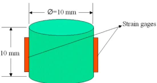
(2) Specimen preparation
An aluminum bar with 10 mm in diameter was purchased, and then was machined into all specimens were 10mm long (Fig. 2.) by using a lathe. The frictional criterion a/h~1 [3] was satisfied by this specimen dimension, and a pair of diametrically opposite strain gages (Micro Measurements EA-06-120LZ-120) was mounted on the specimen to detect the history of its deformation. For the same reason to decrease the effects of friction between the specimen/pressure bar interfaces, all of the specimens’ cross-sections were polished by polishing machine with 30µ and 15µ diamond slurry. Finally, the each specimen’s cross-sections were smooth and paralleled to each other.
(3) Static test
Because AL 6061-T6 was strain-rates insensitively, the mechanical properties nearly the same were obtained under different strain-rates situation. MTS 810 system was used to test aluminum specimen under quasi-static test about strain rate 10-4/s. In order to avoid the effect of different geometry of specimen, the same dimension of specimens were used to carry out the static tests. The feature (Fig. 3.) consists of a hemisphere that can slide smoothly in the block with a hemisphere cavity, and then it can be pressed before testing to provide the same parallel plane as the SHPB apparatus. Moreover, its contact surfaces were also polished and lubricated as the bars’ end surfaces, and then the effects of friction were decreased by this way for quasi-static compression test.
3. SHPB measur ing technique
The split Hopkinson pressure bar measuring technique is based on the one-dimensional wave propagation theorem [10]. This implies that a compressive stress wave propagates non-dispersive in a long elastic bar at elastic bar velocity. The impact of the striker bar at the free end of the incident bar develops a compressive longitudinal incident wave åi(t). Once this wave reaches the incident bar/specimen
interface, and separated into two parts. One of it, år(t), is reflected as a tension wave,
and another part goes through the specimen and develops in the transmission bar the transmitted wave åt(t). The incident wave and the reflected wave recorded by the same
from the strain gages mounted on the transmission bar. Usually, we wanted to approach the time as the start of specimen deformation, so the instant of time in this report was chosen as the arrival of the incident wave at the incident bar/specimen interface.
After the incident wave crossed the incident gages, it needed a time Ä tAB (A, B
are shown in Fig.4) to arrive at the specimen-incident bar interface. The reflected pulse is also recorded by the same set of gages after another time interval Ä tAB. Thus,
the incident pulse åi(t) and the reflected pulse år(t) were both recorded by the same set
of gages on the incident bar, and they are separated by a time period of 2Ä tAB. Thus,
(
AB)
I i =ε t−∆t ε , (1)(
AB)
I r =ε t+∆t ε , (2) Where the strain åI(t) is recorded by the incident gages at any instant of time t.According to these strain åi(t) and år(t), the displacement of the incident bar-specimen
interface u1(t) was determined. Similarly, the strain in the transmission bar was
recorded after a time period of Ä tCD, which is the time taken by the elastic wave to
cross the specimen-the transmission bar interface to Gage B in Fig. 4. Thus,
(
CD)
T t =ε t+∆t
ε , (3) Where åT(t) is the strain recorded by the transmission gages at any instant of time
t.
Then the displacement of specimen/transmission bar interface u2(t) was derived,
and the specimen displacement was calculated as a function of time by analyzing the wave signals were recorded. They could show as follows:
( )
t c ε ε dτ u t r i o∫
− + = 0 1 ( ) , (4)( )
t c ε dτ u t t o∫
− = 0 2 , (5)Where C0 is the longitudinal velocity of the bar.
∫
− + − = − = t t i r s d l c l u u 0 0 0 0 1 2 ( ε ε ε ) τ ε , (6)Where l0is the original specimen length. F1 was compressive force on the
incident bar/specimen interface, and F2 was compressive force on the specimen/the
transmission bar interface.
(
i r)
AE F1= ε +ε , (7) t AE F2 = ε , (8) Where A is the cross-section area of the elastic bar in this report. For stress equilibrium to exist, F1=F2 and åi(t)+ år(t)= åt(t). F2 was chosen to determine the stressin this study, and the stress in the specimen was given by
s s A F2 = σ , (9) The dynamic stress-strain curves are thus extracted from the Hopkinson Bar data by equation (6) and (9).
4. Test r esults
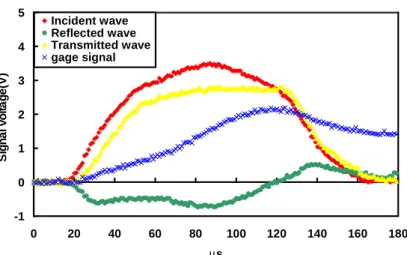
After the striker bar impacted the free end of the incident bar, and the compressive incident wave was generated and it propagated along the incident bar. The wave separated into a reflected wave and a transmitted wave while it reached the incident bar/specimen interface. The three wave signals were acquired by strain gages mounted on the middle of incident bar and transmission bar. The history of specimen deformation was also recorded by strain gages mounted on it. These gages were connected to the Wheatstone bridge circuits to convert strain signals into voltage signals. Then voltage signals were amplified by a signal conditioning and recorded by a digital oscilloscope. The recorded original data were shown in Fig. 5., and the incident and reflected waves on the incident bar, the transmitted wave on the transmission bar, and the specimen strain signal were recorded respectively with sampling rate 10MHz. As shown in Fig. 6., all wave signals were shifted to the instant of time as the start while the incident wave arrived the incident bar/specimen interface.
The displacements u1(t) on the incident bar/specimen interface and u2(t) on the
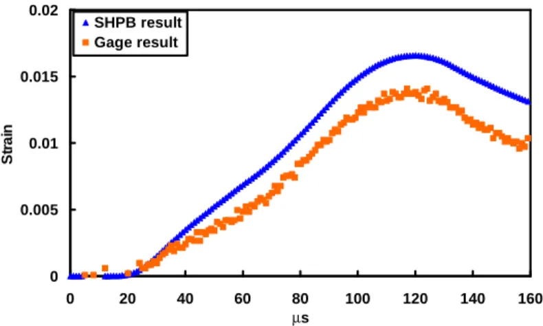
the specimen strain corresponding one-dimensional wave propagation theory was conducted. For comparison, the strain signal was recorded by the strain gages mounted on the specimen (see Fig. 7.). The SHPB result was 15% higher then the gage result, so the gage result that gages mounted on the specimen was chosen to construct the more accurate dynamic stress-strain curves.
The forces between the incident bar/specimen interface and the specimen/transmission bar interface were determined by equations (7) and (8). The histories of F1 and of F2 during a SHPB test were shown in Fig. 8, and the equilibrium
of F1 and F2 indicated that the specimen was homogeneous deformation. The
dynamic stress-strain curve that strain from the gages result was extracted, and it was compared with the static compression test under 0.001 mm/sec by using MTS 810 (Fig. 9.). The young’s modulus and yielding stress from static and dynamic testing were almost the same value, and this indicated that the correction of SHPB apparatus was verified.
5. Conclusion
The mechanical behaviors of aluminum specimens under high strain rate tests and quasi-static tests were carried out by the SHPB apparatus and MTS 810 system, respectively. The young’s moduli and yielding stresses from dynamic and static tests with aluminum specimens were almost the same values, and these results matched the aluminum characteristic of strain rate insensitivity. AS a result, it was indicated that build-up SHPB apparatus is applicable to high strain tests. The dynamic response of nylon 6 and nylon 6/clay nanocomposites will be investigated using the SHPB apparatus in the sequent research.
6. Refer ences
[1] Hopkinson, B. 1914 “A Method of Measuring the Pressure Produced in the Detonation of High Explosives or by the Impact of Bullets,” Philosophical Transactions of the Royal Society of London, A213, pp. 437-456
[2] Kolsky, H. 1949 “An Investigation of the Mechanical Properties of Materials at very High Rates of Loading,”Proceedings of the Physical Society. Section B, Vol.
62, pp. 676-701.
[3] Davies, E. D. H. and Hunter, S. C. 1963 “The Dynamic Compression Testing of Solids by the Method of the Split Hopkinson Pressure Bar,” Journal of the mechanics and physics of solids, Vol.11, pp. 155-178.
[4] Lindholm, U. S. 1964 “Some Experiments with the Split Hopkinson Pressure Bar,” Journal of the mechanics and physics of solids, Vol. 12, pp. 317-335.
[5] Bertholf, L. D. and Karnes, C. H. 1975 “Two-Dimensional Analysis of the Split Hopkinson Pressure Bar System,”Journal of the mechanics and physics of solids;
Vol. 23, pp. 1-19.
[6] Dioh, N. N., Leevers, P. S. and Williams, J. G., 1993 “Thickness Effects in Split Hopkinson Pressure Bar Tests,”Polymer; Vol.34, No. 20, pp. 4230-4234.
[7] Frew, D. J, Forrestal, M. J. and Chen W., 2002 “Pulse Shaping Techniques for Testing Brittle Materials with a Split Hopkinson Pressure Bar,” Experimental Mechanics, Vol. 42, No. 1, pp. 93-106
[8] Ninan, L., Tsai, J. and Sun, C. T. 2001 “Use of Split Hopkinson Pressure Bar for Testing Off-axis Composites,”International Journal of Impact Engineering, Vol.
25, pp. 291-313.
[9] Follansbee, P. S. 1978 “High Strain Rate Compression Testing,” Metals
Handbook, Ninth Edition, American Society for Metals. Materials Park, Vol. 8,
pp.190-207.
[10] Graff, K. F. 1975 Wave motion in elastic solids, pp. 75-134.
7. Tables and Figur es.
Fig. 2. Schematic of aluminum testing specimens.
Fig.3. Schematic of MTS compression test feature
-2 -1 0 1 2 3 4 0 100 200 300 400 500 600 µs Signal voltage(v)
Incident bar signal Transmission bar signal Specimen gage signal
Fig. 5. The signals recorded by oscilloscope.
-1 0 1 2 3 4 5 0 20 40 60 80 100 120 140 160 180 µs Signal voltage(V) Incident w ave Reflected w ave Transmitted w ave gage signal
Fig. 6. All signals were shifted to the instant of time while the incident wave reached the incident bar/specimen interface.
0 0.005 0.01 0.015 0.02 0 20 40 60 80 100 120 140 160 µs Strain SHPB result Gage result
Fig. 7. Comparison of specimen strain recorded by gages result with derived from SHPB analysis result. 0 5000 10000 15000 20000 25000 30000 0 20 40 60 80 100 120 140 160 µs Force(Nt) F1 F2
Fig. 8. The histories of force on the incident bar/specimen interface and on the specimen/transmission bar interface.
0 50 100 150 200 250 300 350 0 0.005 0.01 0.015 0.02 strain stress(MPa) Dynamic test Static test