國 立 交 通 大 學
資訊科學與工程研究所
碩
士
論
文
藉由重新指定暫存器為混合指令集處理器之
程式碼減量
Code Size Reduction with Register Reassignment for
Mixed-Width ISA Processors
研 究 生:顧耀崙
指導教授:楊武 博士
藉由重新指定暫存器為混合指令集處理器之程式碼減量
Code Size Reduction with Register Reassignment for Mixed-Width
ISA Processors
研 究 生:顧耀崙
Student:Yao-Lun Ku
指導教授:楊武
Advisor:Dr. Wuu Yang
國 立 交 通 大 學
資 訊 科 學 與 工 程 研 究 所
碩 士 論 文
A Thesis
Submitted to Institute of Computer Science and Engineering College of Computer Science
National Chiao Tung University in partial Fulfillment of the Requirements
for the Degree of Master
in
Computer Science and Engineering
September 2009
Hsinchu, Taiwan, Republic of China
藉由重新指定暫存器為混合指令集處理器之程式碼
減量
學生:顧耀崙
指導教授:楊 武 博士
國立交通大學資訊科學與工程學系(研究所)碩士班
摘 要
由於嵌入式系統缺乏記憶體,所以程式碼大小成為一個重要的研究議題。基於這個 理由,一些精簡指令集處理器,例如:ARM、MIPS 和 ANDES 都提出混合長度的指令集架 構。此指令集架構支援一般標準長度的指令集,還有一個長度較小的指令集。若一個 32 位元指令能夠被轉換成對應的 16 位元指令,則程式碼大小即能得到縮減。但是 16 位元 指令的暫存器欄位通常只有 3 位元長度,因此 16 位元指令在暫存器的使用上有所限制。 相反地,32 位元指令其暫存器欄位通常有 4 到 5 個位元長度,所以 32 位元指令可以使 用所有的暫存器。因而當 32 位元指令要轉換成對應的 16 位元指令時,可能需要重新指 定暫存器才能讓轉換順利執行。指定暫存器通常以下列兩種方式執行:(1)程式碼產生 器指定適當的暫存器並試著產生 16 位元指令;當無法產生 16 位元指令時,編譯器則會 產生 32 位元指令。(2)編譯器產生出全部為 32 位元的指令,之後再利用一個額外的步 驟去嘗試重新指定暫存器來讓 32 位元指令轉換為對應的 16 位元指令。我們基於上述第 二種方式,提出了兩個快速重新指定暫存器的方法。單純只有轉換而沒有執行我們提出 之重新指定暫存器的方法,程式碼大小平均有百分之二十七的縮減。而我們的實驗結果 顯示在相同的程式底下程式碼大小平均有百分之二十八的縮減。Code Size Reduction with Register Reassignment for
Mixed-Width ISA Processors
Student: Yao-Lun Ku
Advisor: Dr. Wuu Yang
Institute of
Computer Science and Engineering
National Chiao Tung University
Abstract
Due to the limited memory in embedded systems, code size becomes an important issue. For this reason, many RISC processors, such as ARM, MIPS, and ANDES, etc., provide a mixed-width instruction set architecture (ISA). This ISA supports a normal-width instruction set (usually 32-bit) and a short-width instruction set (usually 16-bit). Code size will be reduced if some 32-bit instructions are replaced with 16-bit equivalents. There is a restriction on the registers that can be used by 16-bit instructions because the register field in a 16-bit instruction is usually 3 bits wide. In contrast, in a 32-bit instruction, the register field is usually 4 or 5 bits wide. All registers can be used in 32-bit instructions. Therefore, replacing a 32-bit instruction with the 16-bit equivalent may need to re-assign the registers. Register assignment can be performed in two ways: (1) the code generator will attempt to generate 16-bit instructions and assign appropriate registers to the instructions. When it is not possible to generate 16-bit instructions, the compiler will generate 32-bit instructions instead; (2) the compiler will generate purely 32-bit instructions first. A later pass will attempt to reassign the registers so that as many 32-bit instructions can be converted to 16-bit equivalents as possible. We propose two fast methods based on the second approach. We will call our method register re-assignment. We implemented our method in the LLVM static compiler. The results demonstrate that the code size reduction is 28% with our methods. In contrast, a straightforward translation without register reassignment achieves code reduction of 27% on the same benchmarks.
Acknowledgement
The foremost person I would like to thank is my advisor, Dr. Wuu Yang. This thesis would not been possible without his useful comments and suggestions. I thank him for his continuous guidance let me to complete my research. I also acknowledge him for his patience on improving the readability of this thesis.
I am very grateful to Yu-Sheng who advised me and helped me in various aspects of my research. He guided me about the direction of my thesis from the beginning. Besides, he is the one that I can always count on to discuss the difficulties or the tiniest details of a problem. I thankfully acknowledge discussions with Dr. Wei-Chung Hsu and Dr. Jyh-Jiun Shann. Their helpful and valuable feedbacks inspired me to continue working on my research.
I also thank all the members in PLASLAB and my schoolmates in the university. They are good guys and very kind to me. We enjoy chatting about various topics, such as someone is dating a girl, which baseball team will win the final champion, etc. I really had lots of fun being a member of this fantastic group.
My deepest appreciation goes to my family. Their continued support enabled me to overcome the frustrations during my study. Finally, I would like to show my profound gratitude to my girlfriend, who accompanied me throughout my research.
Table of Contents
摘 要 ... iii
Abstract ... iv
Acknowledgement ... v
Table of Contents ... vi
List of Figures ... viii
List of Tables ... ix
Chapter 1 Introduction ... 1
1.1 Motivation ... 2
1.2 Objective ... 4
1.3 Organization ... 4
Chapter 2 Background and Related Work ... 5
2.1 Mixed-Width ISA ... 5
2.1.1 Constrains of Mixed-width ISA ... 6
2.1.2 Mode Switching Mechanisms ... 6
2.2 Calling Convention ... 9
2.3 Related Works ... 10
Chapter 3 Register Reassignment Methods ... 12
3.1 Compiler Backend and Definition for our Design ... 12
3.1.1 Compiler Backend ... 12
3.1.2 Instruction Types ... 14
3.1.3 Register Set ... 15
3.2 Method I ... 16
3.2.1 Register Selection Phase ... 17
3.2.2 Mapping and Reassign Phase ... 18
3.2.3 Insertion Phase ... 21
3.3 Method II ... 23
3.3.1 Register Selection Phase ... 25
Chapter 4 Experiment ... 27
4.1 Environment ... 27
4.1.1 Benchmarks ... 28
4.3 Experimental Result ... 31 Chapter 5 Conclusion and Future Work ... 35 References... 36
List of Figures
Figure 1-1 Translation rate of 16-bit instructions ... 3
Figure 2-1 Different Instruction Formats in MIPS ... 6
Figure 2-2 ARM branch and exchange (BX) instruction format ... 7
Figure 2-3 Mode switching through bx instruction ... 7
Figure 2-4 ISA Mode bit in ANDES ... 8
Figure 2-5 Mode switching through the ISA mode bit ... 8
Figure 2-6 The standard process of function call ... 9
Figure 3-1 A compiler backend for mixed-width ISA ... 13
Figure 3-2 Different encoding formats of ADDIU instruction ... 14
Figure 3-3 Flowchart of register reassignment method I ... 16
Figure 3-4 Example for counting RACi ... 17
Figure 3-5 Comparison between (a) the code before reassignment and (b) the cod after reassignment ... 20
Figure 3-6 Pseudo code of additional instructions insertion ... 22
Figure 3-7 Relationship between selected register and its neighbors ... 24
Figure 3-8 The difference between Method I and Method II is Register Selection Phase ... 24
Figure 3-9 Building a neighbor graph with weighted edges ... 25
Figure 3-10 Update priority of neighbors of select register ... 26
Figure 4-1 Code Size Reduction of Register Reassignment Methods ... 33
List of Tables
Table 2-1 Register usage in MIPS ... 10
Table 3-1 MIPS Special-Purpose Registers... 15
Table 3-2 An Example of mapping pairs... 21
Table 4-1 Benchmarks in our experiment ... 28
Table 4-2 Factors for calculating ReassignCost ... 29
Table 4-3 Analysis result of main function in CRC32 benchmark ... 29
Table 4-4 The ArgRegs' ReassignCost of main function in CRC32 ... 30
Table 4-5 The RetRegs' ReassignCost of main function in CRC32 ... 30
Table 4-6 Code size reduction and additional instructions of Method I ... 31
Chapter 1 Introduction
In recent years, embedded systems, such as cell phones, PDAs, etc., brought significant impacts on our daily life. Most of these devices come with very limited memory due to consideration of weight, power consumption, or price. On the other hand, more and more sophisticated applications are demanded nowadays in such devices. For instance, encryption software and games are popular in cell phones. These sophisticated applications require a lot of memory. Thus, code size becomes a critical design issue for the embedded devices.
RISC processors have been widely used in embedded systems. They usually offer the benefits of high computing ability and low power consumption. Due to the very uniform instruction format, RISC software commonly suffers from poor code density. On the other hand, large code size requires more accesses to the instruction memory. This potentially increases the instruction cache miss rate and power consumption.
Traditional RISC processors, e.g., 32-bit ARM and 32-bit MIPS, come with fixed-width instructions. Fixed-width ISAs offer good performance at the cost of larger code size. They are not suitable for limited-memory embedded systems. Therefore, newer RISC processors support a narrower instruction set (usually 16-bit wide) in addition to the normal instruction set (usually 32-bit wide). The mixed-width ISA[1] improves poor code density and runs programs with acceptable performance.
There are two limitations in the narrower ISA: First, there are fewer bits in a 16-bit instruction for indexing registers. For instance, in MIPS, all the 16-bit instructions can use only eight registers, $0~$7, but 32-bit instructions can use all registers. Thus, the register allocator in a compiler needs to carefully consider the available registers for individual
instructions. Second, there are fewer bits for encoding immediate values in a 16-bit instruction.
In this thesis, we will assume a traditional compiler that will generate purely 32-bit instructions. Then a new register re-assignment phase will re-arrange the registers so that as many 32-bit instructions can be converted to their 16-bit equivalents as possible. We propose two fast register reassignment methods. Both methods select registers according to their priorities. The main difference between the two methods lies in calculating a register’s priority. The simple reassignment method selects registers based on the usage frequencies of the registers. The second method selects registers based on a dynamically changing neighbor graph.
1.1 Motivation
We found out the restriction of using register does affect the generation of 16-bit instructions, since 16-bit instructions have fewer bits to use registers and hold immediate value. If a register is out of the encodable range of a instruction's 16-bit equivalent (i.e. 16-bit instruction cannot use it), this instruction cannot be converted to 16-bit format. In short, the generation of 16-bit instructions is closely related to registers which are assigned by register allocator. If the register allocator assigns registers without considering the restriction of 16-bit instructions, hence the number of 16-bit instructions would not be many. It quite wastes the characteristic of mixed-width ISA.
In some platform, for example, CVM (CDCHI virtual machine)[2], including a dynamic complier, call Just-In-Time compiler (JITC). It translates Java bytecode into native code dynamically. Because of dynamical compilation of JITC, it cannot perform complicated register allocation, such as graph coloring register allocation. Instead of register allocation, it uses register manager for keeping track of register usage during the compilation processes.
More precisely, the register manager is the resource manager, because what it really does is use a data structure called CVMRMResoure to keep track of where evaluated expressions are currently stored, both in memory and in registers. Hence, this kind of allocation is too simple to use register efficiently. If this JITC is applied on a mixed-width ISA, the generation of 16-bit instructions would not be more since the register management does not allocate registers carefully. Our register reassignment methods can be applied on this platform to improve the registers use.
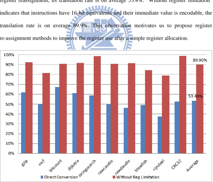
We get the translation rate of the 16-bit instructions by analyzing each benchmark as shown in Figure 1-1. Direct Conversion only performs default register allocation and without register reassignment, its translation rate is on average 53.4%. "Without register limitation" indicates that instructions have 16-bit equivalents and their immediate value is encodable, the translation rate is on average 89.9%. This observation motivates us to propose register re-assignment methods to improve the register use after a simple register allocation.
1.2 Objective
Design a simple and fast method to reduce code size for mixed-width ISA with mode-switch by encoding technique mechanism. The proposed methods achieve code reduction by increasing the generation of 16-bit instructions. Besides, an analysis of the low-level intermediate representation (IR) to evaluate a function is worthy of register reassignment, and to minimize the additional instructions that required for solving the calling convention problem. Our methods are simple and fast enough for adapting to targets likes Just-In-Time run-time compilers.
1.3 Organization
The rest of this thesis is organized as follows: Chapter 2 introduces the background knowledge. Chapter 3 first gives the definition of instruction types and register sets which are used in the register reassignment methods, then gives the overview of compiler back-end for mixed-width ISA and presents the register reassignment methods. Chapter 4 demonstrates the experimental results. Chapter 5 gives the conclusion and the future work.
Chapter 2 Background and Related Work
This chapter describes background knowledge in our research. Section 2.1 introduces the mixed-width ISA, including constrains of narrower instruction set and mode switch mechanisms. In section 2.2, we describe the calling convention, especially calling convention in MIPS ISA, since we face the problem about calling convention in our register reassignment methods.
2.1 Mixed-Width ISA
As the name suggests, the mixed-width ISA contains more than one fixed-width instruction set. Typically, it has two instruction sets of different instruction widths. The normal instruction set (usually 32-bit) provides good performance and the narrow instruction set (usually 16-bit) provides high code density. The narrow instruction set is usually a subset of the normal instruction set. Processors with mixed-width ISA are popular in embedded systems, such as ARM with Thumb ISA[3][4], MIPS with MIPS16e ISA[5], or Andes with AndeStar ISA[6], and so on.
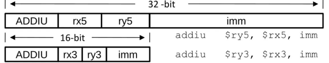
Code generating by using mixed-width ISA may achieve significant code size reduction since the 16-bit instruction has half width against with the 32-bit instruction. Because of this, there are some bit width restrictions. Due to the bit width limitation of narrow instruction set, it usually encodes the most frequently used operations from normal instruction set; in addition, it also has fewer bits to use registers and immediate value. Figure 2-1 show the different width register field and immediate value of different width instructions.
ADDIU rx3 ry3 imm addiu $ry3, $rx3, imm
ADDIU rx5 ry5 imm
addiu $ry5, $rx5, imm
16-bit
32 -bit
Figure 2-1 Different Instruction Formats in MIPS
2.1.1 Constrains of Mixed-width ISA
A 16-bit instruction could use only a subset of the registers. For example, the register field of a typical MIPS 16-bit instruction, shown in Figure 2-1, consists of three bits. Thus, it could only use eight registers (i.e., R0 through R7). RegS denotes the set of these registers. An
instruction that uses any registers not belonging to Regs must be encoded as a 32-bit instruction. If the compiler does not take into account this restriction when assigning registers of the instructions, these instructions may not be able to encode as 16-bit equivalents. Thus, a compiler needs to be careful to allocate registers for instructions.
In addition to the limitation on accessible registers, immediate values in a 16-bit instruction are also restricted to fewer bits. For example, the encodable bits of 16-bit addiu instruction are five in Figure 2-1; that is, the maximum unsigned value the instruction can be expressed is 31. There are 16 bits for the immediate value in the 32-bit instruction and only 5 bits in the 16-bit instruction. Large immediate values also force generation of 16-bit instructions, but it depends on compiler how to hold the constants. The impact of this constrain might be eliminated as if compiler uses a constant pool to hold large immediate values.
2.1.2 Mode Switching Mechanisms
Multiple fixed-width ISAs do not come without a cost. There is the cost for switching among the different modes. There are two mode-switching mechanisms:
i. Use a Mode Switch Instruction
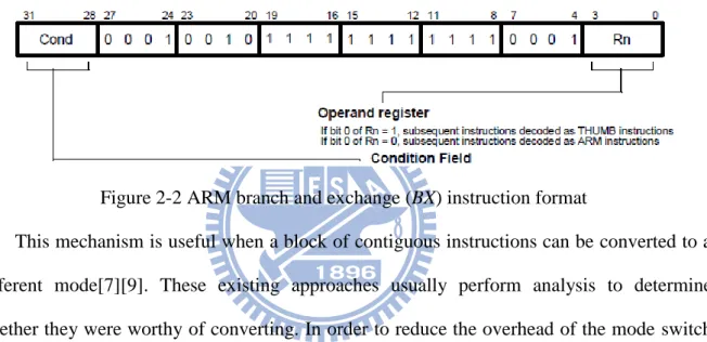
ARM/Thumb uses a branch instruction (e.g., Branch and exchange, BX) as mode switching instruction to change modes between different width code sections. Figure 2-2 shows a branch-and-switch-mode instruction in ARM, it performs a branch by copying the contents of a general register, Rn, into the program counter, PC. The value of Rn[0] determines whether the instruction stream will be decoded as ARM or Thumb instructions during execution.
Figure 2-2 ARM branch and exchange (BX) instruction format
This mechanism is useful when a block of contiguous instructions can be converted to a different mode[7][9]. These existing approaches usually perform analysis to determine whether they were worthy of converting. In order to reduce the overhead of the mode switch instructions, every subroutine is compiled in a single mode in ARM/Thumb. The mode switching between ARM and Thumb code is shown as Figure 2-3.
.code 16 ... ; Thumb code(16-bit) .align 2 bx r15 .code 32 ... ; ARM code(32-bit) orr r15, r15, #1 bx r15
ii. Use the encoding technique
This mechanism uses a mode bit to indicate the mode bit of the instruction. For example, in AndeStar, the first bit of every instruction is an “ISA mode bit”. This bit indicates if the instruction is 16-bit or 32-bit. Hence, 16-bit and 32-bit instructions can be mixed together without the mode-switching instructions. Figure 2-4 shows how the ISA mode bit in ANDES. Instruction is 32-bit if bit[31] equals zero; likewise, instruction is 16-bit if bit[15] equals one. The obvious disadvantage of this mechanism is that it needs to reserve a bit for ISA mode bit.
31 24
0
1 opcode
15
ISA mode bit opcode
0 0
Figure 2-4 ISA Mode bit in ANDES
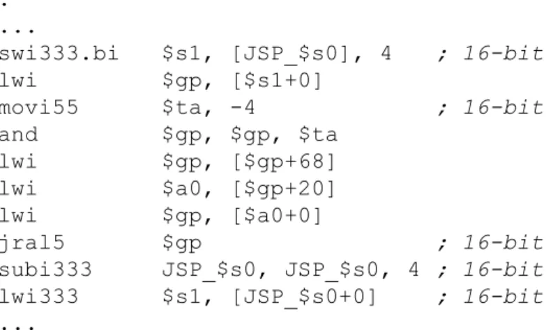
Because of AndeStar uses the mode bit to indicate instruction format, it’s not required as same as switching mode through mode switch instruction which needs to compile entirely code segment into identical width. 16-/32-bit instructions can spread all over the function arbitrarily (e.g., instruction-level granularity). Figure 2-5 shows an AndeStar code fragment; the instructions swi333.bi, movi55, jral5, subi333, and lwi333 are 16-bit. Others are 32-bit. B.S. Liang et al. [8] show that the mode switching by using encoding technique is an efficient way for multiple fixed width instruction sets in instruction-level.
BB1: ...
swi333.bi $s1, [JSP_$s0], 4 ; 16-bit
lwi $gp, [$s1+0]
movi55 $ta, -4 ; 16-bit and $gp, $gp, $ta lwi $gp, [$gp+68] lwi $a0, [$gp+20] lwi $gp, [$a0+0] jral5 $gp ; 16-bit subi333 JSP_$s0, JSP_$s0, 4 ; 16-bit lwi333 $s1, [JSP_$s0+0] ; 16-bit ...
2.2 Calling Convention
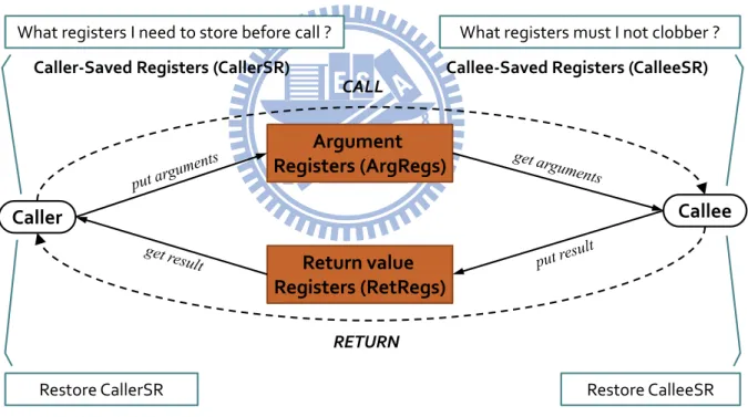
The calling convention is a scheme for how functions receive arguments from their caller and how they return a value. The calling conventions can differ in follows:
Where arguments and return values are placed (in registers; on the call stack; or a mix of both).
The order in which arguments are passed.
How the task of setting up and cleaning up a function call is divided between the caller and the callee.
Which registers that may be directly used by the callee.
Caller Callee
Argument Registers (ArgRegs)
Return value Registers (RetRegs)
What registers I need to store before call ?
Caller-Saved Registers (CallerSR)
CALL
RETURN
What registers must I not clobber ?
Callee-Saved Registers (CalleeSR)
Restore CalleeSR Restore CallerSR
Figure 2-6 The standard process when function call
Figure 2-6 shows the standard process when the caller calls to callee. First, we need to store the caller-saved registers before call and put parameters into Arguments Registers (ArgRegs), then caller changes control to callee. Callee-saved registers must be preserved before the callee use them. So callee stores callee-saved registers to stack frame in prolog and restored them in epilog before changing control to caller. The return value of callee is stored
in Return value Register (RetRegs). After callee returns, the caller gets the return value of callee from RetRegs.
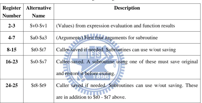
In MIPS, the register usage is shown in Table 2-1. The ArgRegs are $4-$7, and the
RetRegs are $2, $3. The first four arguments are passed in ArgRegs, and the rest of arguments
are stored in stack frame. The arguments pass order is started from $4 to $7 (i.e. the first argument is passed to $4, the second is passed to $5, and so on).
Table 2-1 Register usage in MIPS Register
Number
Alternative Name
Description
2-3 $v0-$v1 (Values) from expression evaluation and function results 4-7 $a0-$a3 (Arguments) First four arguments for subroutine
8-15 $t0-$t7 Caller-saved if needed. Subroutines can use w/out saving
16-23 $s0-$s7 Callee-saved. A subroutine using one of these must save original and restore it before exiting.
24-25 $t8-$t9 Caller saved if needed. Subroutines can use w/out saving. These are in addition to $t0 - $t7 above.
2.3 Related Works
Due to the restriction of the Thumb instruction set, it leads to generation of poorer quality code that leads to the loss of performance. For establishing above claims, Krishnaswamy and Gupta [9] present analysis of Thumb instruction set restrictions. Besides, they proposed a profile guided algorithms for generating mixed ARM and Thumb code for application programs, not only achieve significant code size reduction but also without loss in performance. There two generation of mixed code in this thesis, coarse grained and fine
grained. The coarse grained approach using heuristic for choosing ARM or Thumb code for frequently executing function (more than 5% of total execution time); Thumb code for all other functions. Each function compiles entirely into either ARM code or Thumb code. A function must be compiled into ARM code if it result in significantly lower overall performance when generating in Thumb code.
In fine grained approach, a function is compiled into mixed ARM and Thumb code. Because of some functions the Thumb version has greater number of instructions than ARM version and result in decreasing overall performance. To make the decision for a single function whether it would result in better overall result or not, they analyzed the instruction counts of the benchmarks. They found frequently occurring patterns in Thumb code from four instruction types which increase the overall Thumb instruction counts significantly. Afterward the patterns are compiled into equivalent ARM code and insert the bx instruction to switch modes.
Halambi et al. [7] presents a novel compilation framework for dual instruction sets, which uses a profitability base compiler heuristic to convert normal instructions into reduced width instructions. In this thesis, the compiler first marked all convertible instructions and looked for rISABlocks which were composed of contiguous candidate instructions. Thereupon a profitability heuristic evaluated each rISABlock to determine whether it is worthy of converting rISABlocks into reduced format by estimating the tradeoff between code size and performance. Lastly the compiler inserted a mode change instruction to switch between normal and reduced mode. Since this compiler framework was designed for architectures with mode switch by a branch instruction, it is not suitable for architectures which indicate the instruction format by instruction encoding mechanism.
Chapter 3 Register Reassignment Methods
We propose two simple and fast register reassignment methods for reducing code size in this thesis. These methods are designed for mixed-width ISA processor with the mode bit to indicate the instructions' width (16-bit or 32-bit). Register reassignment methods are performed after register allocation to improve the generation of 16 bit instructions by means of reassigning registers with higher priority. Both methods process one function at a time. The function that is under processing is denoted as CurrentFunction in the following discussion.
In this chapter, section 3.1 first describes the compiler backend and the definition of instruction types and register sets. Section 3.2 presents the first reassignment method and the solution for handling calling convention problem. Section 3.3 presents the second reassignment method and the neighbor-graph. The second method is different from first method in calculation of registers' priorities.
3.1 Compiler Backend and Definition for our Design
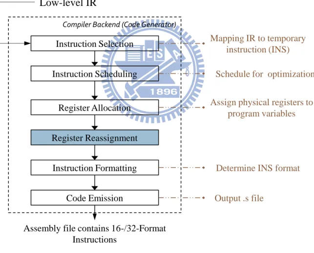
Figure 3-1shows the overall structure of a compiler backend with a register reassignment phase. The input for the register re-assignment phase is the program in the form of LLVM IR, in which the instructions have already been selected and the registers have already been allocated. The register re-assignment phase attempts to re-arrange the registers in the program. Finally, a code emitter will write the resulting program as an assembly file.
3.1.1 Compiler Backend
A traditional compiler backend performs the following functions: instruction selection,
instruction scheduling, register allocation, and code emission. In the instruction selection
phase it uses a pattern-matching scheme to map the low-level intermediate representation (IR) to target-machine instructions. The instruction scheduling phase is for speed optimization,
which improves instruction-level parallelism (ILP) by rearranging the order of instructions to avoid pipeline stalls. The register allocator allocates program variables to physical registers. Finally, the code emitter outputs the machine code.
Several frequently used instructions have both 16-bit and 32-bit versions. The main differences between the two versions are their encoding length and accessible registers. So we first map operations in the IR to the temporary instructions (called INS) in the instruction selection phase, shown in Figure 3-1. Our register reassignment methods take the INSs as input and the output is still the INSs, but the registers may have been reassigned.
Compiler Backend (Code Generator) Instruction Selection Instruction Scheduling Register Allocation Register Reassignment Instruction Formatting Code Emission
Assembly file contains 16-/32-Format Instructions
Mapping IR to temporary instruction (INS)
Schedule for optimization
Assign physical registers to program variables
Determine INS format
Output .s file
Low-level IR
Figure 3-1 A compiler backend for mixed-width ISA
An additional instruction formatting phase is added after the register reassignment phase. It performs the translation from INS to the instruction of the proper format according to the
re-assigned registers. In this phase, we first check if a INS has 16-bit version. For example, the addition (addiu) INS has two 16-bit versions, shown in Figure 3-2. Then one of the 16-bit versions is selected based on the operands of INS. For instance, addisup is selected if the base register is $sp and the offset is within its encodable range.
ADDIU rx3 ry3 imm addiu $ry3, $rx3, imm
addiu $rx3, $sp, imm
ADDIUSP rx3 imm
16-bit
Figure 3-2 Different encoding formats of ADDIU instruction
3.1.2 Instruction Types
Every instruction (abbreviated as INS) in the program, which is 32 bits wide, is classified into the following three types: L-INS, U-INS, and S-INS.
1) L-INS (Long-Format INS)
An instruction of this type indicates that it has no 16-bit equivalent or its immediate value is out of the encodable range of 16-bit instructions. An L-INS cannot be converted to a 16-bit instruction.
2) U-INS (Uncertainly-Format INS)
An instruction is classified as U-INS if it has 16-bit equivalents but the registers the 16-bit equivalents can use are restricted. This kind of INS might be converted to its 16-bit equivalent if the registers can be properly re-arranged. This kind of instruction is the target of our register reassignment methods.
3) S-INS (Short-Format INS)
An instruction of this type has 16-bit equivalents and the 16-bit equivalents can use all physical registers. In MIPS, all and only JALR, JR, and NOP instructions are S-INSs. For example, the JALR instruction has just one register operand, which contains an
instruction address; it can access all physical registers. An S-INS can always be converted to a 16-bit instruction with or without register reassignment.
3.1.3 Register Set
Owning to the limited number of bits for indexing registers, we denote the physical registers that can be used by 16-bit instructions as RegS. The number of registers in RegS is
denoted as NRS. For example, in MIPS, 3 bits are reserved in a 16-bit instruction to designate
a register. Thus, it can index registers from $0 to $7. In fact, a 16-bit instruction can only access registers $1~$7, since $0 always contains zero in MIPS. In addition, a few registers are reserved for special purposes. For example, $28 is the global pointer and $29 the stack pointer, etc.
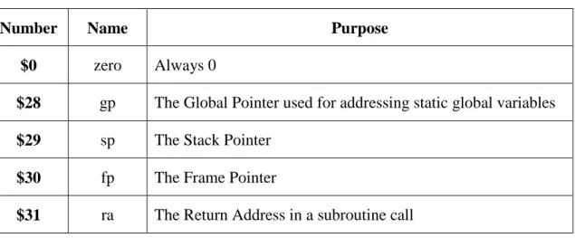
Table 3-1 shows the special-purpose registers in MIPS. These registers are sometimes used in the special way. For example, some instructions, such as addisup in Figure 3-2, use $29 (i.e., $sp)implicitly. They are called the SP-Relative instructions. In our methods, we do not re-assign these special-purpose registers. Hence, we denote RegL as the set of all but the
special-purpose registers.
Table 3-1 MIPS Special-Purpose Registers
Number Name Purpose
$0 zero Always 0
$28 gp The Global Pointer used for addressing static global variables $29 sp The Stack Pointer
$30 fp The Frame Pointer
3.2 Method I
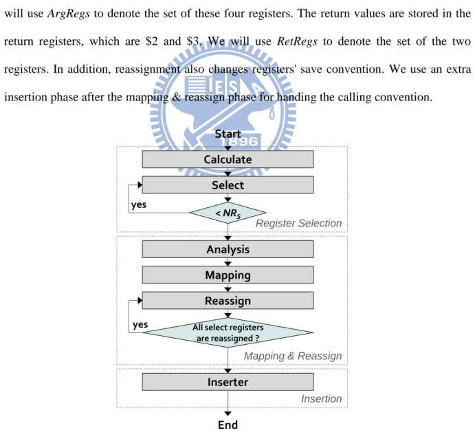
The Method I is the basic design among our register reassignment methods. It consists of three phases: Register Selection, Mapping & Reassign, and Insertion, shown in Figure 3-3. We count the number of times each register is used in CurrentFunction. This count is regarded as the priority of the register. Then the registers, in the order of their priorities, are re-assigned to registers in RegS.
Register reassignment is under several constraints. In the calling convention, arguments are stored in the argument registers, which are $4, $5, $6, and $7 in MIPS architecture. We will use ArgRegs to denote the set of these four registers. The return values are stored in the return registers, which are $2 and $3. We will use RetRegs to denote the set of the two registers. In addition, reassignment also changes registers' save convention. We use an extra insertion phase after the mapping & reassign phase for handing the calling convention.
Start
Mapping & Reassign Register Selection Calculate Select < NRS Mapping Reassign
All select registers are reassigned ? Insertion yes Inserter yes Analysis End
3.2.1 Register Selection Phase
In this phase we first inspect individual functions and calculate the priority of each register belonging to RegL that have been used in an U-INS. We select the general purpose
register (GPR) currently. Calculation focuses on registers used in U-INSs since they might be converted to 16-bit instructions. The priority of a register is defined as follows:
Priorityi denotes the priority of register i (e.g., the priority of $22 is denoted as Priority22).
RACi denotes the number of times register i is used in U-INSs. For example, the U-INS "add
$2, $3, $4" has three register operands. Therefore, RAC2, RAC3, and RAC4 are incremented by
one, respectively. Figure 3-4 shows an example. RAC2 is 8 not 9 in Figure 3-4 since JR is not
a U-INS. Thus, we do not count it. The main task of the register selection phase is to select k registers with the highest priorities, where k is NRS or the number of registers used in U-INSs,
whichever is smaller. $BB1_14: # bb581 lw $3, %got($JTI1_1)($gp) nop addiu $3, $3, %lo($JTI1_1) sll $2, $2, 2 addu $2, $2, $3 lw $2, 0($2) nop lw $3, 28($sp) nop addu $2, $2, $3 jr $2 nop j $BB1_16 # bb666 nop
RAC
2= 8
RAC
3= 6
3.2.2 Mapping and Reassign Phase
Register reassignment might reassign registers to others such ArgRegs and RetRegs, which sometimes contain specific values. In this situation we to insert additional instructions to handle this problem (see the insertion phase below). These additional instructions increase the code size. This conflicts with our objective, i.e. code size reduction. Therefore, we need to determine if a function is worthy of register reassignment by comparing the overhead and the profits of reassignment.
Every register which belongs to RegS and to either ArgRegs or RetRegs is given a cost,
called ReassignCost. In our implementation, ReassignCosti denotes the code size of the
additional instructions for handling the calling convention if register i is reassigned to another register. If register i belongs to neither ArgRegs nor RetRegs, then ReassignCosti is 0. We get
the following information for calculating ReassignCost by analyzing the low-level IR in the analysis stage:
i. Arguments
Both arguments of CurrentFunction and arguments of the functions called in
CurrentFunction are stored in ArgRegs. We figure out the number of arguments of Current Function that have been passed in ArgRegs. Besides, we record the number of
arguments of each function call in CurrentFunction. ii. Return Value
A call might return a value that is stored in RetRegs. Both $2 and $3 are needed to hold a 64-bit return value. We need to determine whether only $2 or both $2 and $3 are needed for the return value.
iii. ReassignCost
InstrSize denotes the total size (measured in bytes) of the additional instructions per call
that are required for solving the calling convention problem. NCi means the number of
function calls inside CurrentFunction that have passed arguments or return value into register
i (register i must belong to either ArgRegs or RetRegs). MovArgISi denotes the size of the
instruction for moving the arguments of CurrentFunction from register i to the new register.
MovRetValISi denotes the size of the instruction for moving the return value of Current
Function to register i.
The mapping stage maps the selected registers to RegS. The mapping relationship is a set
of mapping pairs. For example, the mapping pair "$16-$5" indicates that $16 is mapped to $5. The reassignment stage later will replace the registers according to mapping pairs. The mapping is performed according to the following two rules:
i. If a register selected in the register selection phase belongs to RegS, it is mapped to
itself. This means that the register will not be replaced.
ii. The rest of the registers selected in the register selection phase are mapped to registers in RegS that have not been mapped yet. These registers are mapped from
highest priority to lowest one until all selected registers have been mapped.
Our register reassignment methods need inserting additional instructions for conforming to calling convention. When CurrentFunction calls other functions many times, a lot of additional instructions might be added. Thus, not every function is suitable for register reassignment.
For this reason, we inspect CurrentFunction to calculate the total code size reduction if we reassign registers according to the mapping pairs. Afterwards we compare the code size
with the total cost, which is shown as follows. Register reassignment is performed on the
CurrentFunction only if the code size reduction is larger than TotalCost.
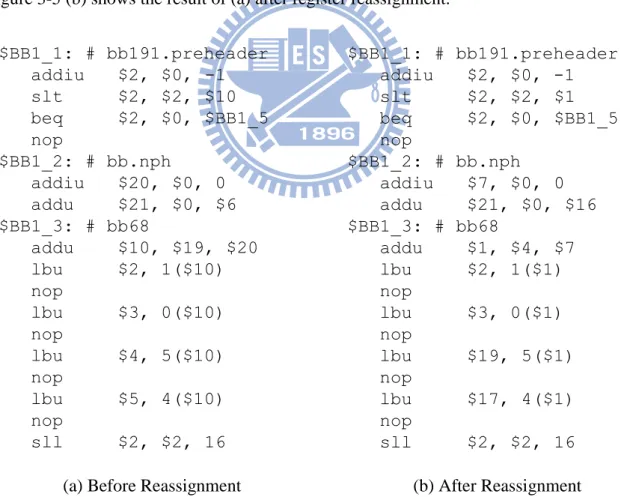
After finishing mapping stage it is time for reassigning. Reassignment is done according to the mapping pairs. Figure 3-5 (a) shows a fraction of function before register reassignment. In reassign stage it performs reassignment according to the mapping pairs as shown in
Table 3-2. For a mapping pair, such as “$10-$1”, all the appearances of $10 in
CurrentFunction is replaced with $1. Similarly, all appearances of $1 is replaced with $10.
Figure 3-5 (b) shows the result of (a) after register reassignment.
$BB1_1: # bb191.preheader addiu $2, $0, -1 slt $2, $2, $10 beq $2, $0, $BB1_5 nop $BB1_2: # bb.nph addiu $20, $0, 0 addu $21, $0, $6 $BB1_3: # bb68 addu $10, $19, $20 lbu $2, 1($10) nop lbu $3, 0($10) nop lbu $4, 5($10) nop lbu $5, 4($10) nop sll $2, $2, 16 $BB1_1: # bb191.preheader addiu $2, $0, -1 slt $2, $2, $1 beq $2, $0, $BB1_5 nop $BB1_2: # bb.nph addiu $7, $0, 0 addu $21, $0, $16 $BB1_3: # bb68 addu $1, $4, $7 lbu $2, 1($1) nop lbu $3, 0($1) nop lbu $19, 5($1) nop lbu $17, 4($1) nop sll $2, $2, 16
(a) Before Reassignment (b) After Reassignment
Figure 3-5 Comparison between (a) the code before reassignment and (b) the cod after reassignment
Table 3-2 An Example of mapping pairs
Select Registers
Reg
S$10 $1 $2 $2 $3 $3 $19 $4 $17 $5 $16 $6 $20 $7
3.2.3 Insertion Phase
We deal with the calling convention problem in this phase. The calling convention problem is that registers which contain arguments or return value are re-assigned to another registers, or registers' saving convention (e.g., caller-saved vs. callee-saved) are changed. The caller must save caller-saved registers before calling the callee. The callee-saved registers must be saved by the callee before using them. This problem is solved by inserting additional instructions to keep the values of these registers.
Because of the register reassignment replaces a register with another register. Thus, there are two cases, "callee-saved registers (CalleeSR) after reassignment" and "caller-saved registers (CallerSR) after reassignment". Note that we assume both ArgRegs and RetRegs belong to CallerSR in our solution. The following is our solution for the calling convention problem:
Procedure Insertion
if a CalleeSR has reassigned then if new register is still CalleeSR then
Modify offset of PreserveCalleeSR if need; else /* it reassigned to CallerSR */
Remove PreserveCalleeSR; for each function call Insert PreserveCallerSR; endfor
endif
else if a CallerSR has reassigned then if new register is still CallerSR then /* Do nothing here */
else /* it reassigned to CalleeR */ Insert PreserveCalleeSR;
if there existed PreserveCallerSR then
Remove them since the register has been changed. endif
endif
if this CallerSR is ArgRegs then Insert MovFuncArg after prolog; for each function call
Insert PreserveArgRegs;
Insert MovCallsArg precede the call and succeed the PreserveArgRegs; endfor
endif
if this CallerSR is RetRegs then for each RET in function
Insert MovFuncRetValue precede RET instruction; endfor
for each function call which needs to return a value Insert PreserveRetRegs;
Insert MovCallRetValue succeed the call and precede the PreserveRetRegs; endfor
endif endif
PreserveCalleeSR are a consecutive sequence of instructions that store callee-saved
registers in the stack frame in prolog and load them from the stack frame in epilog. Similarly,
PreserveCallerSR are a consecutive sequence of instructions that store caller-saved registers
in the stack frame before function call and load them from the stack frame after the call returns. MovFuncArg are a sequence of MOVE instructions which move arguments of
CurrentFunction from ArgRegs to new registers. MovCallsArg are a sequence of MOVE
instructions which move arguments of a function call from new registers to ArgRegs, since arguments are in the new registers after register reassignment. Both MovCallRetValue and
MovFuncRetValue are a sequence of MOVE instructions that moves the return value of a
function call from RetRegs to new registers and moves the return value of CurrentFunction from new registers to RetRegs, respectively. PreserveArgRegs are a sequence of instructions which store ArgRegs in the stack frame before a function call and load them from the stack frame after the call returns. PreserveRetRegs is similar to PreserveArgRegs with ArgRegs replaced by RetRegs.
3.3 Method II
In order to generate more 16-bit instructions, we modify the priorities. The purpose of this modification is to create more opportunities for the “neighbors” of the selected registers. Two registers are “neighbors” if they are used in the same instruction. We may construct a neighbor-graph for a piece of code in which nodes represent registers and edges represent the neighborhood relation. Consider the store-word instruction "sw $8, 0($5)" in BB5_11 shown in Figure 3-7 (a). The neighbor-graph for the code in Figure 3-7 (a) is shown in Figure 3-7 (b). If $5 is mapped to a register in RegS, $8 must also be mapped to a register in RegS otherwise
the instruction still cannot be replaced with a 16-bit version. To this end we add weights to the edges in the neighbor graph in which the weight of an edge denotes the number of times the two vertices (i.e., registers) are accessed in the same instructions.
Method II has three phases as well as Method I, but the different part from Method I is the selection phase. The selection phase of Method II has added two extra stages, "Build
Graph" and "Update Priority" as shown in Figure 3-8.
$BB5_11: # bb13 addiu $4, $4, 1 sw $8, 0($5) addiu $5, $0, 18 bne $4, $5, $BB5_3 nop $BB5_12: ... $BB5_15: ... addu $gp, $0, $3 lw $3, 20($sp) nop addu $2, $18, $2 sw $3, 72($2) lw $3, 24($sp) ... Neighbor of selected register The selected register
$5
$8
$18
$4
$2
$3
(a) Example code for neighbors (b) Neighbors of registers Figure 3-7 Relationship between selected register and its neighbors
Start
Mapping & Reassign
Register Selection Calculate Select < NRS Insertion yes End Start
Mapping & Reassign
Register Selection Calculate Select < NRS Insertion yes End Build Graph Update priority
(a) Method I (b) Method II
3.3.1 Register Selection Phase
As in Method I, the priority of a register is the number of times the register is used in U-INSs. When a register is selected in select stage, the priorities of its neighbors will be adjusted, as follows. Assume register Ra and register Rb are neighbors. After Ra is selected, the weight of the edge between Ra and Rb is added to the priority of Rb. This increases the likelihood of Rb being selected.
Figure 3-9 shows an neighbor graph example. $6 is used in seven instructions in BB3_3, and its priority is nine since it has been used twice in two instructions. The weight between $6 and $5 is four since they have been accessed together in three instructions. Note that if an instruction has three register operands and two of them are the same register, such as "sltu $6, $10, $6" and "addu $5, $5, $6" in Figure 3-9, the weights of these registers are two rather than one. $10 is mapped first because it has the highest priority. Then we add the edge weights to its neighbors' priorities (i.e., $2, $4, $6, etc). The updated priorities of registers are shown in Figure 3-10. Keep selecting k registers with the highest priorities, where k is NRS or the
number of registers used in U-INS, whichever is smaller.
$4 $11 $15 $12 $2 $14 $13 $24 $10 $6 $5 9 6 1 1 1 2 4 1 1 5 12 1 1 1 6 4 1 2 1 1 1 1 1 1 2 $BB3_3: # bb2 srl $6, $5, 31 addu $10, $2, $6 sltu $6, $10, $6 addu $5, $5, $6 sll $6, $5, 31 srl $10, $10, 1 or $6, $10, $6 addiu $10, $0, 48 mult $6, $10 mfhi $10 sra $5, $5, 1 addu $11, $10, $4 lw $10, -16($11) nop lw $11, -12($11) nop xor $14, $10, $13 sltu $15, $11, $12 slt $24, $10, $13 sltu $14, $14, 1 bne $14, $0, $BB3_5 nop Priorityi Weight
$4 $11 $15 $12 $2 $14 $13 $24 $6 $5 15 6 2 2 2 4 5 1 1 7 1 4 1 1 1 1 1 Priorityi Weight
Chapter 4 Experiment
This chapter shows the experimental environments and presents the experimental results.
4.1 Environment
In our experiment we use Low-Level Virtual Machine (LLVM) [10][11] as our compiler infrastructure. It is a new compiler architecture built with reusable components. LLVM replaces GGC optimizer and code generator, and reuses GCC parser and runtime libraries (llvm-gcc front-end). The LLVM's back-end supports many common architectures, such as x86, PowerPC, ARM, MIPS, etc, and it is composed of many passes, e.g., mid-level optimizer, instruction selection, register allocator, etc. A pass manager takes a list of passes, ensures their prerequisites are set up correctly, and then schedules passes to run efficiently.
The low-level intermediate representation (IR) is generated from LLVM's front-end and the IR is in Static Single Assignment (SSA) form. Our compiler back-end takes the low-level IR as its input and outputs the assembly file. To generate the INS, we modified the LLVM back-end to produce the INS with virtual registers. The LLVM default register allocator then performs register allocation on these INSs. Afterward register reassignment method reassigns these INSs.
The MIPS/MIPS16e is the target ISA in our experiment, and we assume the instruction mode is changed by instruction encoding mechanism (i.e. using a bit to indicate instruction format, 16-/32-bit Format) rather than using mode switch instructions. The RegS = $1 ~ $7
since $0 is used as ZERO in MIPS, and thus NRS = 7. The special purpose registers are $0, GP,
SP, FP, and RA in MIPS. Besides, both $26 and $27 are reserved for kernel used. Hence, excluding special purpose registers and kernel reserved registers, RegL = $1 ~ $25.
4.1.1 Benchmarks
We select some benchmarks from MiBench[12], MediaBench[13], and SPEC INT2000[14]. The programs of each benchmark are shown as Table 4-1.
Table 4-1 Benchmarks in our experiment
Benchmark Programs
SPEC INT2000 164.gzip, 181.mcf MiBench rawcaudio, rawdaudio
MediaBench automative-bitcount, network-dijkstra, offstring-stringsearch, security-blowfish, security-rijndael, telecomm-CRC32
4.2 ReassignCost
Registers such as ArgRegs, RetRegs, contain specific value are given a ReassignCost. We will describe the calculation of ReassignCost in this section. There are four ArgRegs (e.g., $4, $5, $6, and $7) and two RetRegs ($2 and $3) in MIPS. The first four argument are pass to
ArgRegs, and the pass order is started from $4 to $7 (i.e. the first argument is passed to $4, the
second is passed to $5, and so on). If there are more than four arguments, the rest of them will store in stack frame. Normally, the return value is stored in $2, but if the return value is larger than one register could hold, $3 will be used.
Basically, a 32-bit instruction is 4 bytes and a 16-bit instruction is 2 bytes. We need four additional instructions (i.e. sw, lw, addu(as move instruction), and NOP after lw instruction) per call for handling calling convention. Therefore, the InstrSize is equal to 10 bytes since three of these additional instructions can be converted to 16-bit equivalents. MovArgIS and
MovRetValIS are move instructions, their size are 4 bytes. Note that ArgRegs do not use in
returning value, so their MovRetValISi is zero. Similarly, the MovArgISi of RetRegs are zero.
Table 4-2 Factors for calculating ReassignCost
Register i InstrSize (bytes) MovArgISi (bytes) MovRetValISi (bytes)
$2-$3 10 0 4
$4-$7 10 4 0
Next we get the NCi from analysis phase, and we calculate each ReassignCosti according
to it. For example, we get the analysis result of main function in CRC32 benchmark, as shown in Table 4-3. There are two arguments of CRC32's main function, so we need to insert two
move instructions after prolog to move values from $4 and $5 to their own new registers, if
both $4 and $5 have been reassigned. The ReassignCost of ArgRegs are shown in
Table 4-4. There are eight function calls of CRC32's main function, indexing from 0 to 7. The
ReassignCost4 is 84 bytes because InstrSize × NC4 = 80 and plus MovArgIS4 (4 bytes).
Table 4-3 Analysis result of main function in CRC32 benchmark Name of Calls Index # of Arguments Registers used
fopen 0 2 $4, $5 _IO_getc 1 1 $4 perror 2 1 $4 _IO_getc 3 1 $4 ferror 4 1 $4 perror 5 1 $4 fclose 6 1 $4
Table 4-4 The ArgRegs' ReassignCost of main function in CRC32 Registers
i
NCi Have used in arguemtns of
CurrentFunction? ReassignCosti (Bytes) $4 8 Yes 10×8+4 = 84 $5 2 Yes 2×8+4 = 20 $6 1 No 1×8 = 8 $7 1 No 1×8= 8
We find out the RetRegs were be selected in most cases by observing each mapping pairs of all benchmarks. That means RetRegs do not reassign to new registers at most of time, hence we seldom insert additional instructions for them. Besides, we cannot know the exact numbers of RetRegs precisely that both CurrentFunction and function calls are required. Accordingly, we do not analyze for the return value of function calls or CurrentFunction. But if any RetRegs has been reassigned, we assume it is used in storing the return value of all function calls (i.e. eight function calls in CRC32's main function) and the CurrentFunction. Then we have to insert additional instructions for them to conform with calling convention. Table 4-5 shows the ReassignCost of RetRegs. In this table we know $2 has been reassigned, so ReassignCost2 is the sum of InstrSize*NCi and MovRetValISi.
We get the TotalCost by summing up all ReassignCost. The TotalCost of CRC32's main function is larger than the code size reduction we could get, so we leave this function unchanged.
Table 4-5 The RetRegs' ReassignCost of main function in CRC32 Register i NCi Has been reassign? ReassignCosti (Bytes)
$2 8 Yes 10×8+4 = 84
4.3 Experimental Result
This section presents the performance of our register reassignment methods. We use direct translation as the baseline for comparison. In direct translation, we examine each instruction in turn, converting it to a 16-bit version if possible. We calculate the code size and the ratio of additional instructions under the two register re-assignment methods, respectively. In last section we show the analysis by comparing two methods and give summary.
Table 4-6 Code size reduction and additional instructions of Method I Number of Instructions Original Code Size After RR Code Size Code Size Reduction (%) Additional Instructions (%) gzip 17,497 69,988 47,208 32.55% 1.81% mcf 7,428 29,715 21,646 27.15% 0.94% bitcount 352 1,408 920 34.66% 0.00% dijkstra 490 1,960 1,356 30.82% 0.00% stringsearch 213 852 596 30.05% 3.76% rawcaudio 217 868 652 24.88% 0.00% rawdaudio 209 836 642 23.21% 0.00% blowfish 4,277 17,108 11,982 29.96% 3.30% rijndael 4,622 18,488 14,806 19.92% 0.09% crc32 165 660 486 26.36% 0.00% Average 27.96% 0.99%
Table 4-7 Code size reduction and additional instructions of Method II Number of Instructions Original Code Size After RR Code Size Code Size Reduction (%) Additional Instructions (%) gzip 17,497 69,988 47,260 32.47% 1.45% mcf 7,428 29,715 21,604 27.29% 0.92% bitcount 352 1,408 920 34.66% 0.00% dijkstra 490 1,960 1,356 30.82% 0.00% stringsearch 213 852 594 30.28% 3.76% rawcaudio 217 868 652 24.88% 0.00% rawdaudio 209 836 642 23.21% 0.00% blowfish 4,277 17,108 11,998 29.87% 1.40% rijndael 4,622 18,488 14,692 20.53% 0.17% crc32 165 660 486 26.36% 0.00% Average 28.04% 0.77%
The result is shown in Figure 4-1, where the code size reduction of Method I is on average 27.96% and Method II is 28.04%. Direct Conversion achieves code reduction of 26.7% in the same benchmark programs. Register re-assignment is not done on rawcaudio, rawdaudio, and CRC32 the cost is larger than the profit. We could get more code reduction from larger programs, such as gzip, mcf, blowfish, and rijnadel, and from functions that make few function calls.
Figure 4-1 Code Size Reduction of Register Reassignment Methods
Compared with Method I, Method II has no significant improvement in reducing code size. The reason is that the weight used in Method II, which is simply the number of times two registers are used in the same instructions, should be biased toward instructions with fewer register operands. Different instructions might have different numbers of register operands. For converting a 32-bit instruction to a 16-bit equivalent, all the register operands used in the instruction must be mapped to registers in RegS.
Figure 4-2 shows the additional instructions rate in each benchmark program. The rate of Method I is on average 0.99%, and Method II is 0.77%. As a rule of thumb, the more ArgRegs and RetRegs are reassigned to other registers, the more additional instructions are inserted. In blowfish, the additional instructions ratio in Method I is much higher than that in Method II, since the largest function in blowfish is profitable for conversion in Method I but is not so in Method II. Hence, Method II will leave the function unchanged, but Method I will perform register reassignment on it. This causes numerous additional instructions.
Figure 4-2 Additional Instruction Rate
There are no additional instructions in rawcdaudio, rawdaudio, and CRC32, since register reassignment is not done on them. Because the stringsearch benchmark is small, the overhead is relatively high. The bitcount benchmark has no additional instructions because in lots of functions, all the registers are mapped to themselves. The rijndael benchmark has lower cost than others since the mapping pairs in most functions do not cause the calling convention problem.
Chapter 5 Conclusion and Future Work
In this thesis we present two register re-assignment methods for mixed-width ISA. On the average, the two methods reduce 28% of the code size. In contrast, a direct translation reduces 26.7% of the code. If a ArgRegs or RetRegs have been reassigned, and at the same time they are used for arguments or the return value, the reassignment comes with a cost. We could get more code reduction from larger programs, such as gzip, mcf, blowfish, and rijnadel, and from functions that make few function calls.
From the experimental results, we observed that the effects of Method I and Method II are not much different. The main reason might be that the weights do not consider the number of register operands in an instruction. We plan to modify the weights by taking the number of operands into consideration in the future.
References
[1]. A. Krishnaswamy and R. Gupta, "Mixed-Width Instruction Sets," In Communications of the ACM, Vol. 46, No. 8, 2003
[2]. Sun Microsystems. CDC HotSpot Implementation Dynamic Compiler Architecture
Guide, 2005
[3]. S. Furber. ARM System Architecture. Addison-Wesley, 1996. ISBN 0-201-40352-8. [4]. ARM Corporation. Thumb ISA. http://www.arm.com/products/CPUs/ARM7TDMI.html [5]. MIPS32 Architecture for Programmers Volume IV-a: The MIPS16 Application Specific
Extension to the MIPS32 Architecture. 2001
[6]. Andes Technology. Andes Instruction Set Architecture Specification, 2008.
[7]. Aviral Shrivastava, Partha Biswas, Ashok Halambi, Nikil Dutt, Alex Nicolau,
"Compilation framework for code size reduction using reduced bit-width ISAs (rISAs),"
ACM Transactions on Design Automation of Electronic System (TODAES), v.11 n.1, p.123-146, January 2006.
[8]. Bor-Sung Liang, June-YuhWu, Jih-YiingLin, Ming-Chuan Huang, Chi-Shaw Lai, Yun-Yin Lien. Ching-HuaChang, Pei-Lin Tsai, Ching-PengLin, SunplusTechnol. Co., Ltd., Hsinchu, Taiwan. "Instruction set architecture scheme for multiple fixed-width
instruction sets and conditional execution". 2005 IEEE VLSI-TSA International
Symposium on VLSI Design, Automation and Test, 2005. (VLSI-TSA-DAT).
[9]. A. Krishnaswamy and R. Gupta, "Profile guided selection of ARM and Thumb
instructions." In Proceedings of LCTES/SCOPES, Berlin, Germany, June 2002.
[10]. Chris Lattner and Vikram Adve. "LLVM: A compilation framework for lifelong program
generation and optimization: feedback-directed and runtime optimization, p.75, March 20-24, 2004, Palo Alto, California
[11]. C. Lattner et al. The LLVM Compiler Infrastructure. http://llvm.org/
[12]. Matthew R. Guthaus, Jeffrey S. Ringenberg, Dan Ernst, Todd M. Austin, Trevor Mudge, Richard B. Brown, "MiBench: A free, commercially representative embedded benchmark
suite", IEEE 4th Annual Workshop on Workload Characterization, Austin, TX,
December 2001.
[13]. C. Lee, M. Potkonjak, and W. H. Mangione-Smith, "MediaBench: A tool for evaluating
and synthesizing multimedia and communications systems," in Proceedings of the 30th
Annual International Symposium on Microarchitecture, (Research Triangle Park, North Carolina), pp. 330-335, Dec. 1-3, 1997.
[14]. SPEC: Standard Performance Evaluation Corporation. http://www.spec.org, September 2000.