國
立
交
通
大
學
網路工程研究所
碩
士
論
文
行動環境下基於社交網路之階層式 P2P SIP 系統
A Hierarchical Social Network-based P2P SIP System
for Mobile Environments
研 究 生:李柏威
指導教授:王國禎 博士
行動環境下基於社交網路的階層式 P2P SIP 系統
A Hierarchical Social Network-based P2P SIP System
for Mobile Environments
研 究 生:李柏威 Student:Bo-Wei Li
指導教授:王國禎 Advisor:Kuochen Wang
國 立 交 通 大 學
資 訊 學 院
網 路 工 程 研 究 所
碩 士 論 文
A ThesisSubmitted to Institute of Network Engineering College of Computer Science
National Chiao Tung University in Partial Fulfillment of the Requirements
for the Degree of Master
in
Computer Science June 2008
Hsinchu, Taiwan, Republic of China
行動環境下基於社交網路之階層式 P2P SIP 系統
學生:李柏威 指導教授:王國禎 博士
國立交通大學 資訊學院 網路工程研究所
摘 要
在多媒體領域中,由於 P2P SIP 能夠克服傳統 SIP 系統的缺點,所以 P2P
SIP 系統的研究已成為一個新趨勢。大多數的 P2P SIP 系統是以基於分散式
雜湊表(DHT)的 Chord 路由演算法實作,使其能夠提供系統擴充性和可靠
性。然而以往的研究並未同時考慮節點異質性、節點所在位置資訊與節點
移動性。也就是說,每個節點應該視其能力(計算、儲存及頻寬)賦予適當
的角色。另外,兩個使用者間傳送網路信號的延遲與其距離有很大的關聯,
這將會大大的影響連線建立的時間。此外,網路中的節點不斷的加入與離
開,將會需要額外的訊息以維護一個穩定的 DHT 網路,且會增加連線建立
的延遲時間。在本論文中,我們提出一個基於社交網路之階層式 P2P SIP 系
統,其中社交網路的性質能夠增加與朋友建立通話時的路由效率,而我們
採用的混合式(結構式/非結構式)網路架構更能適用於節點不斷加入與離
開的情況。模擬結果顯示,相較於傳統 Chord 架構的 P2P SIP 系統,我們能
夠減少百分之三十二與非朋友之連線建立延遲時間,並且減少百分之六十
三的系統維護花費。除此之外,我們將資源尋找的效率由 O(logN)提升至
O(1),其中 N 為 DHT 網路的節點數目。
關鍵詞:連線建立延遲時間,行動環境,P2P SIP,社交網路。
A Hierarchical Social Network-based P2P SIP
System for Mobile Environments
Student:Bo-Wei Li Advisor:Dr. Kuochen Wang Department of Computer Science
National Chiao Tung University
Abstract
P2P SIP (peer to peer session initiation protocol) systems have emerged as a new trend in multimedia realm due to their abilities to overcome the shortcomings of conventional SIP systems. Most of P2P SIP systems were implemented using Chord, a Distributed Hash Table (DHT) based routing algorithm which can provide scalability and reliability. Previous studies on P2P SIP systems did not consider node heterogeneity, location information and mobility issues all together. For node heterogeneity, nodes with different capabilities (processing power, storage and bandwidth) should be treated suitably. For location information, the signaling latency is correlated with the geographic distance between end users. This will influence call setup latency greatly. As to mobility, the node churn property will involve additional messages to maintain a stable DHT-based network and increases call setup latency. To conquer these problems, we propose a hierarchical social network-based P2P SIP system. The social network property can increase routing efficiency when calling friends. In addition, the proposed hybrid (structured/unstructured) overlay is more resilient to cope with node churn. Simulation results show that our approach can improve 32% call setup latency with non-buddies and reduce 63% maintenance cost in comparison with the conventional Chord-based approach. In addition, we improve lookup efficiency from O(logN) to O(1) when making calls with buddies, where N is the number of nodes in a DHT-based network.
Acknowledgements
Many people have helped me with this paper. I deeply appreciate my thesis advisor, Dr. Kuochen Wang, for his intensive advice and guidance. I would like to thank all the classmates in the Mobile Computing and Broadband Networking Laboratory (MBL) for their invaluable assistance and suggestions. This work was supported by the National Science Council under Grants NSC96-2628-E-002-138-MY3 and NSC96-2628-E-009-140-MY3.
Contents
Abstract (in Chinese) ... i
Abstract (in English) ... iii
Acknowledgements ... iv
List of Figures ... vii
List of Tables ... viii
Chapter 1 Introduction ... 1
1.1 Basic concept of SIP ... 1
1.2 Basic concept of P2P ... 1
1.3 P2P classification ... 2
1.4 Basic concept of P2P SIP ... 2
1.5 Proposed P2P SIP system consideration ... 2
Chapter 2 Related Work ... 5
2.1 Features of a P2P telephony system ... 5
2.2 Feature comparison between various P2P SIP systems ... 5
Chapter 3 System Design ... 8
3.1 System overview ... 8
3.2 Contacts initiation ... 10
3.3 Super node selection ... 10
3.4 Node startup, node registration and user registration ... 11
3.5 Session setup and user location ... 15
Chapter 4 Simulation ... 18
4.1 Simulation setup ... 18
Chapter 5 Conclusions and Future Work ... 22
5.1 Conclusions ... 22
5.2 Future work ... 22
Bibliography ... 23
List of Figures
Fig. 1. A routing example operating on PlanetLab [15] [25]. ... 3
Fig. 2. Overlay network for the proposed P2P SIP system. ... 9
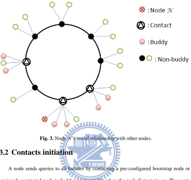
Fig. 3. Node N ’s social relationship with other nodes. ... 10
Fig. 4. Node startup procedure for the proposed P2P SIP system. ... 12
Fig.5. Difference between iterative and recursive routing when a node proceeds to node registration. ... 14
Fig.6. Difference between iterative and recursive routing when a node proceeds to user registration ... 16
Fig. 7. Session setup with a buddy node. ... 17
Fig. 8. Session setup with a non-buddy node. ... 17
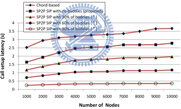
Fig. 9. Comparison of call setup latency under various number of nodes. ... 19
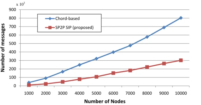
Fig. 10. Comparison of maintenance cost under various number of nodes. ... 20
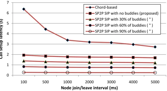
Fig. 11. Comparison of call setup latency under various churn rates. (Churn rate increases to the left)….. ... 21
List of Tables
Table 1. Features comparison between different P2P SIP systems. ... 7
Table 2. Comparison of search overhead and search time between different P2P SIP systems. 7
Chapter 1
Introduction
1.1 Basic concept of SIP
In recent years, voice over IP (VoIP) has become a very popular Internet service. Session Initiation Protocol (SIP) [1] which was defined by Internet Engineering Task Force (IETF) is widely applied to VoIP because its simplicity and expansibility. SIP is an application layer signaling protocol, which is used for establishment, maintenance, and termination of a communication session between two or more participants. In conventional SIP, it is a centralized architecture which includes user agent, proxy server, registrar server, redirect server and location server. Unlike some proprietary protocols, such as SKYPE [2], SIP-based IP telephony has an additional advantage of achieving interoperability. It means a SIP-based system can inter-work with any existing SIP-based system. However, the centralized architecture results in some shortcomings, such as limited scalability, high cost of development and maintenance as well as a single point of failure.
1.2 Basic concept of P2P
Peer-to-Peer (P2P) networks share resources such as processing power, storage and bandwidth between peers. Nodes reside in P2P networks are interconnected with each other [17]. In large P2P networks, each node directly connects to a group of neighbors and uses these connections to reach the other nodes in the network. P2P systems inherently have scalability, low maintenance cost and high fault tolerance because of no centralized server and self-organized nature.
1.3 P2P classification
In general, P2P networks can be classified into unstructured and structured ones. Unstructured P2P networks, such as Kazaa [3] and Gnutella [4], build a random graph and use flooding or random walks on that graph to discover data stored by overlay nodes. Broadcasting messages using by these systems will burden the network with unnecessary traffic. However, unstructured P2P network is more resilient to cope with node churn (the continuous process of node arrival and departure) [23][24]. On the other hand, structured P2P networks use DHT-based algorithm such as Chord [5], CAN [6] and Pastry [7] to provide a lookup service in a distributed fashion. Nodes construct an overlay with a predicable way and adopt efficient routing instead of blind and unpredictable search by flooding.
1.4 Basic concept of P2P SIP
P2P SIP studies have emerged as a new trend in multimedia realm. The combination of SIP and P2P can overcome the shortcomings of conventional SIP systems. IETF P2P SIP Internet drafts define a Chord-based P2P SIP system [21][22]. A node in a P2P-SIP system acts as a conventional SIP-UA (SIP-user agent), registrar as well as a proxy/redirect server. Traditional SIP lookup service has been replaced by P2P overlay lookup service. Therefore, a node in a P2P SIP system can perform all functions of traditional SIP-UA without a need of a centralized SIP server. P2P SIP systems benefit from scalability and reliability offered by P2P. However, P2P SIP overlay based on Chord, the resource lookup procedure takes O(logN) hops which is larger than traditional SIP’s lookup latency of O(1), where N is the number of nodes in the overlay [8]. Therefore, our design goal is to speed up the lookup procedure as close to that of a traditional SIP system as possible.
1.5 Proposed P2P SIP system consideration
network, all nodes are treated equally and there is no difference between nodes. However, in a real world, nodes have different capability, such as different processing power, storage and bandwidth. Furthermore, node availability also affects indirectly the availability of a P2P system [18]. For example, if a node has longer uptime and better fault tolerance in the system, other nodes can use its service much more to reduce the churn rate. Thus, nodes with greater resources and desirable features should be grouped as super nodes (SN) while the rest of nodes are categorized as ordinary nodes (ON). In addition, lookup routing in DHT networks may be through public Internet, which may introduce significant call setup latency [20]. Fig. 1 shows a routing example operating on PlanetLab [15][25]. In this figure, node numbers 1 through 5 represent a routing sequence. The physical locations of nodes in a DHT overlay are unpredictable so that the routing path may not be optimal, which significantly increases the call setup latency. Thus, an efficient lookup mechanism has to be considered in DHT-based systems. Besides, node mobility is another critical issue that should be paid attention to. Node churn involves additional maintenance messages to ensure a stable DHT-based network, and it increases call setup latencies [11].
In this thesis, we propose a hierarchical social network-based P2P-SIP system. In our system, nodes are categorized as an SN or ON according to their capability. SNs form a main net based on Chord and each SN manages a group of ONs, called a sub net. For a specific SN, all ONs in the same sub-net are its part of online friends, called buddies. The concept behind this proposed system is that users usually call their friends instead of strangers. In addition, people’s friend relationships are closely associated [11]. For example, if we want to call a friend without his phone number, we can still ask our common friends to get the phone number. Thus, in our system, nodes can contact friends by referring to their contacts (common friends) to speed up the look up procedure.
The rest of the thesis is structured as follows. In the next chapter, we review related work and list features that should be involved in a P2P telephony system. In Chapter 3, we present the design approach of our system. Chapter 4 evaluates simulation results. Finally, Chapter 5 gives conclusion and future work.
Chapter 2
Related Work
2.1 Features of a P2P telephony system
Based on existing P2P SIP systems, a P2P telephony system should include the following features: zero configuration, node heterogeneity, efficient lookup, advanced services, interoperability as well as churn handling, which are defined as follows [8]:
Zero configuration: The system should automatically construct an overlay. Node heterogeneity: Nodes with different capabilities should be treated suitably.
Efficient lookup: Blind search based on flooding is not suitable for IP telephony systems. DHT-based routing is a better way to optimize the lookup service.
Advanced services: Offline voice messaging, multi-party conferencing and instant messaging etc. should be supported in the system.
Interoperability: It should easily integrate with existing protocols and IP telephony systems. SIP can support this property.
Churn handling: It should be resilient while nodes join/leave the overlay frequently.
2.2 Feature comparison between various P2P SIP systems
The features comparison between the proposed system and other approaches is shown in Table 1. SOSIMPLE [9] used SIP and Chord [5] to build a decentralized and standards-based system for SIP communications. However, SOSIMPLE did not consider node heterogeneity and churn handling. DChord [10] considered node heterogeneity and location information of nodes to build a full distributed and open P2P-SIP system. Yet, node churn still burdens the
system with extra maintenance messages. UP2P SIP [11] proposed an unstructured P2P SIP with regard to mobility churn and friend relationships. This approach outperforms the conventional Chord-based P2P SIP approach in terms of call setup latency and maintenance cost. However in an unstructured environment, it still involves unnecessary flooding messages when calling for non-buddy nodes and initiating the network. Furthermore, UP2P SIP did not consider node heterogeneity and advanced services such as off-line messages. In addition, UP2P SIP needs an extra host server to build an unstructured P2P network for non-buddies. Table 2 shows the comparison of search overhead and search time between different P2P SIP systems. The search overhead refers to the number of hops that involve in one search. For Chord-based systems, such as SOSIMEPLE [9] and DChord [10], the search overhead and search time are both O(logN). For DChord, because its unstructured nature, the flooding message will involve O(N) hops, and its non-buddies network can guarantee O(logN) search time. As to our proposed SP2P SIP (Social P2P SIP) system, the search overhead and search time are same as those of Chord-based approaches when making calls to non-buddies. However, for calls to buddies, our approach can achieve O(1) for both metrics.
Table 1. Features comparison between different P2P SIP systems.
Approach
Feature
SOSIMPLE [9] DChord [10] UP2P SIP [11] SP2P SIP (Proposed)
Zero configuration Yes Yes Yes Yes Efficient lookup Yes Yes No Yes
Interoperability Yes Yes Yes Yes Node heterogeneity No Yes No Yes
Advanced services Yes Yes No Yes Churn handling No No Yes Yes
Table 2. Comparison of search overhead and search time between different P2P SIP systems.
Approach Search overhead Search time
Chord-based[9][10] O(logN) O(logN) UP2P SIP [11] O(N) O(logN) SP2P SIP with non-buddies (proposed) O(logN) O(logN)
Chapter 3
System Design
In this chapter, we present our system architecture as well as design considerations behind the proposed SP2P SIP (Social P2P SIP) system.
3.1 System overview
In our system, the overlay network, as shown in Fig. 2, is constructed in a hybrid (structured/unstructured) fashion. Considering node heterogeneity, nodes are categorized as super nodes (SNs) or ordinary nodes (ONs) according to their capability. SNs form a structured overlay, called main net, which is based on Chord. Each SN manages a group of ONs that form an unstructured overlay, called sub net. Each SN maintains a finger table, a sub node table as well as a resource table to support resource publishing and location. A finger table is designed for Chord algorithm to speed up the lookup procedure. A sub node table is used for managing ONs, and a resource table is used for managing resource publishing data. In addition, as shown in Table 3, each node maintains a contact table, which comprises buddies and contact’s IP address, to achieve better lookup efficiency when calling buddies. The reason for choosing such a hybrid overlay is that structured P2P networks (DHTs) are much suitable for IP telephony due to its better ability to locate rare files than unstructured P2P networks [13][14]. Besides, unstructured P2P networks are more resilient to cope with node churn [12].
The node social relationship of our system is illustrated in Fig. 3. For a specific ON N, if node N wants to call a friend, it can ask their common friend, called a contact, to get the
conta and n by re our a telep unpr in th hops act informat non-buddies eferring to t approach ca phony applic edictable no he same sch to access a tion. SNs co s. Node N m these contac an significa cations. In a ode in Cho ool or the s a contact tha Fig. 2. Ov onsist of no maintains a cts while lo antly reduce addition, th rd because same countr an an unpred verlay netw on-buddies a list of cont ocating non-e call snon-etup he time to ac friends usu ry. In pract dictable nod
ork for the p
and contact tacts so that -buddy nod latency wh ccess a con ually stay cl ice, it requi de in Chord proposed SP s, whereas O t it can locat des is done i hich is an i ntact is less lose geogra ires a small d. P2P SIP sys ONs compr te buddies i in O(logN). impotent re than time t aphically, fo ler number stem. rise buddies in O(1) hop Therefore, equest in IP o access an or example, of physical s p , P n , l
Fig. 3. Node N ’s social relationship with other nodes.
3.2
Contacts initiation
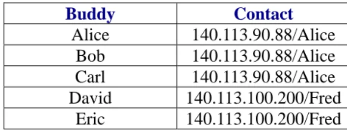
A node sends queries to all buddies by contacting a pre-configured bootstrap node or a previously contacted node to build a contact table when the node first starts up. The contact table is shown in Table 3. Each entry is a mapping of a buddy and the IP address of a contact. A contact is the super node of the buddy. If a buddy is a super node, its contact will be itself. We assume that a node can get a buddy list. In practice, user information, such as a buddy list and preferences, can be managed by a centralized authentication server or stored as an encrypted file within the overlay [9].
3.3 Super node selection
When a node M wants to join the overlay, it has to select a super node among contacts. The first priority is the one who was last connected. If the last contact is not available, a super node should be the one who includes the most number of buddies of M. For example, in Table
3, the super node should be the IP name pair 140.113.90.88/Alice. By this rule, one can build a minimal number of contacts.
Table 3. Contact table for speeding up the lookup procedure.
Buddy Contact Alice 140.113.90.88/Alice Bob 140.113.90.88/Alice Carl 140.113.90.88/Alice David 140.113.100.200/Fred Eric 140.113.100.200/Fred
3.4 Node startup, node registration and user registration
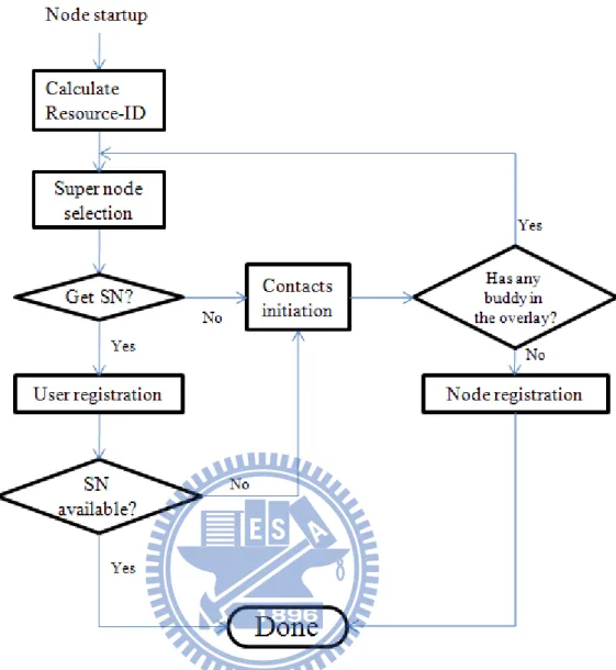
The node startup procedure is shown in Fig. 4. Once a user enters his/her SIP URI, such as [email protected], a user identifier, Resource-ID, will be calculated first by hashing the SIP URI. The default hashing algorithm in Chord is SHA-1 [26], which can produce consistent hashing results. Second, the user performs the super node selection. If there are no contacts to select, contacts initiation will proceed. When there are no buddies in the overlay, contacts initiation will fail. Then, node registration will be executed.
Fig. 4. Node startup procedure for the proposed SP2P SIP system.
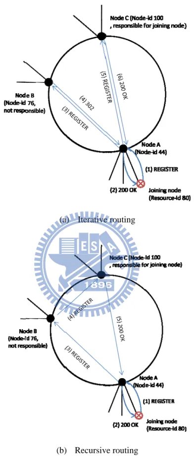
Node registration refers to a node that joins the main net and acts as a super node. The new node uses Resource-ID as its Node-ID. Next, it uses SIP REGISTER and “302 Moved Temporarily” messages to locate the closest successor, which is responsible for accepting the joining node. It is an iterative routing fashion. However, in practice, our main net DHT overlay is much stable so that using recursive routing style is another good way to improve routing efficiency. Fig. 5 illustrates the difference between them. In iterative routing, as shown in Fig. 5(a), the joining node with Node-ID 80 first sends a REGISTER message to the bootstrap node, which has Node-ID 44 (step 1). For a specific Resource-ID k in Chord, the first node with Node-ID equal to or greater (mod the size of the namespace) than k is the
responsible node for k. The bootstrap node is not currently responsible for the joining node so it returns a “302 Moved Temporarily” message, which includes information about the node that might be responsible for the joining node, in this case, node A (step 2). Then, the joining node repeats this procedure to send a REGISTER message to node A. Also, node A is not responsible for it (steps 3-4). Finally, the correct node, node B, is indicated, and it response a “200 OK message” to the joining node, and then the node registration is finished (steps 5-6). Node B is also the location where offline messages for the joining node should be placed. On the other hand, in recursive routing as shown in Fig. 5(b), the bootstrap node and node A acts as SIP Proxy Servers to relay the REGISTER message to node B. After the node registration, the joining node becomes a super node, and Node Startup is done. The differences between recursive and iterative routing are described as follows. First, iterative routing can easily keep track of the lookup route and can react to routing problems rapidly. Second, when a node on the routing path fails, iterative routing can skip all previous hops and continue the lookup somewhere next to the absent node. Third, wrong finger table entries are the main problem with recursive routing. However, in an error-free environment, recursive lookups require only 60% of the lookup time compared to iterative routing [19].
When a node gets a super node in Super Node Selection, it will become an ordinary node, and proceeds User Registration. User Registration refers to a node publishing its location information (the mapping of Resource-ID and IP address) so that other nodes can locate it. There are two places where the location information should be registered to. One is the node’s SN, the other is the node that is responsible for it in the main net. The iterative fashion is shown in Fig. 6(a). The joining node first registers itself to its SN, node A. Node A then adds the joining node to its sub node table, and response “200 OK” message (steps 1-2). Next, the message is relayed to node C, which is responsible for the joining node (steps 3-5). Finally, node C puts the location information to its resource table, and returns a “200 OK” message to
node routi mess Fi e A. The rou ing fashion sage. ig. 5. Differ uting proce is shown in rence betwe ss is the sam n Fig. 6(b). (a (b een iterative me as in no SNs act as a) Iterative b) Recursive e and recurs registrat ode registrat s SIP Proxy routing e routing sive routing ion. tion. On the y Servers to when a nod e other hand o relay the R de proceeds d, recursive REGISTER s to node e R
3.5 Session setup and user location
When a node wishes to establish a session, the target node must be located. This process is called User Location. For example, if Alice wishes to locate Bob, she first calculates Bob’s Resource-ID by hashing Bob’s SIP URI. There are two cases of User Location. One case is that if Bob is one of Alice’s buddies, Alice can refer to Bob’s contact to locate Bob’s IP address, as shown in Fig. 7. Alice first sends SIP MESSAGE or INVITE message to Bob’ contact for an instant message or a multimedia call, respectively (step 1). Then, the contact responds 302 Moved Temporarily message to indicate Bob’s IP address (step 2) so that Alice can send INVITE to Bob, and Session Setup is completed. The other case is shown in Fig. 8. If Bob is a non-buddy node, Alice first finds the node that is responsible for Bob to get Bob’s location (steps 1-4). This process is same as User Registration. Once Bob is located, the session is initiated (step 5).
F
Fig. 6. Difference betwe
(a (b) een iterative a) Iterative ) Recursiv e and recurs registrat e routing ve routing sive routing tion
F Fig Fig. 7. Sess g. 8. Sessio sion setup w n setup with with a buddy h a non-bud y node. ddy node.
Chapter 4
Simulation
4.1 Simulation setup
In this chapter, the performance of our proposed system is evaluated and discussed. Most of P2P SIP systems were implemented with Chord, and Chord is a DHT-based algorithm which was defined in IETF Internet drafts [21][22]. The Chord-based approach is a representative approach so that we chose it for comparison. We used Overlay Weaver [15] as an overlay generator to construct a standard Chord-based P2P SIP system and the proposed system. By the default setting of Overlay Weaver, the namespace of Chord used in both systems is 2160 and the routing style is an iterative fashion. Besides, in order to closely relate to real people’s social relationship, we developed a crawler to extract the buddy relation from [16]. There are two assumptions in our simulation. First, in most situations, the proposed system is not the first launch. Second, SNs are very stable in the overlay so that a node can be connected to the previous SN most of the time. Based on the two assumptions, the overhead of contacts initiation will not be included.
4.2 Simulation results
The call setup latency is a critical property for telephony system. In DHT-based P2P SIP systems, the call setup latency consists of lookup latency and INVITE transaction latency. Lookup latency takes up about 80% of call setup latency [20], so we simply measure call setup latency in terms of lookup latency. In general, most of our friends are in the same country, so we assume connections between a specific node and its contacts are in domestic
networks. Besides, we assume routing in DHT overlay is through the global Internet because physical positions of those nodes on the routing path are unpredictable. In addition, according to realistic statistics [20], we set average hop latency in the domestic network and the Internet to 90 ms and 400 ms, respectively. Fig. 9 shows the call setup latency against the number of nodes in the system with different percentages of calls to buddies. It is obvious that the more calls to buddies the lower call setup latency on average. Our approach outperforms the standard Chord-based system in all scenarios. For example, in 10,000 nodes overlay, the proposed SP2P SIP system improves 86% of call setup latency compared to the standard Chord-based system while making 30% of calls to buddies.
Fig. 9. Comparison of call setup latency under various number of nodes.
We also evaluate the maintenance cost of two schemes by measuring number of control messages which is needed to build a DHT overlay, as shown in Fig. 10. The messages of our approach increase gently as the number of nodes increases because our approach can reduce the number of nodes in the DHT overlay. For example, in a 10,000 nodes overlay, our system requires only 37% of maintenance cost compared to the Chord-based system.
0 0.5 1 1.5 2 2.5 3 3.5 4 1000 2000 3000 4000 5000 6000 7000 8000 9000 10000 Call setup la te ncy (s) Number of Nodes Chord‐based SP2P SIP with no buddies (proposed) SP2P SIP with 30% of buddies ( " ) SP2P SIP with 60% of buddies ( " ) SP2P SIP with 90% of buddies ( " )
Fig. 10. Comparison of maintenance cost under various number of nodes.
To evaluate the effect of node mobility, we first established a network of 1,000 nodes. We churned nodes with various churn rates in a period of 1 minute, which meant nodes continually join/leave overlay with various time intervals, maintaining the total overlay size at 1000. Fig. 11 shows the effect of various churn rates on call setup latency. Higher churn rate will increase call setup latency in the traditional Chord-based P2P SIP system. However, the churn rate affects our system slightly. That is because most nodes in our system are ONs and ONs join/leave the system would not affect the structure of the main net. Thus, the main net can remain stable and is more resilient to cope with node churn.
0 100 200 300 400 500 600 700 800 900 1000 2000 3000 4000 5000 6000 7000 8000 9000 10000 Number of messag es Number of Nodes Chord‐based SP2P SIP (proposed) x 103
Fig. 11. Comparison of call setup latency under various churn rates. (Churn rate increases to the left) 0 1 2 3 4 5 6 7 100 500 1000 2000 3000 4000 5000 Call setup latency (s) Node join/leave interval (ms) Chord‐based SP2P SIP with no buddies (proposed) SP2P SIP with 30% of buddies ( " ) SP2P SIP with 60% of buddies ( " ) SP2P SIP with 90% of buddies ( " )
Chapter 5
Conclusions and Future Work
5.1 Conclusions
In this thesis, we have presented a hierarchical social network-based P2P SIP system. The idea behind the system is that people’s friend relationships are closely associated so we can ask a known friend to get more information about other friends. In addition, friends are close geographically so that we can speed up the lookup procedure. Simulation results have demonstrated that the proposed P2P SIP system improves 32% of call setup latency with non-buddies and reduce 63% of maintenance cost in comparison with the conventional Chord-based approach. We also improve lookup efficiency from O(logN) to O(1) when making calls with buddies, where N is the number of nodes in a DHT-based network. As to mobile environments, the proposed hybrid (structured/unstructured) overlay is more resilient to cope with node churn.
5.2 Future work
Since the numbers of buddies among super nodes are not uniform, the load balancing of super nodes is an issue. In addition, there is a security issue when using P2P SIP architectures for real-time communication [27]. Both of the issues deserve for further study.
Bibliography
[1] J. Rosenberg, H. Schulzrinne, G. Camarillo, A. Johnston, J. Peterson, R. Sparks, M. Handley and E. Schooler, “SIP: session initiation protocol,” RFC3261, IETF, June 2002 [2] “Skype Technologies,” [Online]. Available: http://www.skype.org/.
[3] N. Leibowitz and M. Ripeanu and A. Wierzbicki, “Deconstructing the Kazaa network,” in Proc. of the 3rd IEEE Workshop on Internet Applications (WIAPP), pp. 112-120, June 2003.
[4] M. Ripeanu, “Peer-to-peer architecture case study: Gnutella network,” in Proc. of the 1st IEEE International Conference on Peer-to-Peer Computing, pp. 99-100, August 2001. [5] I. Stoica, R. Morris, D. Karger, M. F. Kaashoek and H. Balakrishnan, “Chord: A scalable
peer-to-peer lookup service for internet applications,” in Proc. of the Conference on Applications, Technologies, Architectures, and Protocols for Computer Communications, pp. 149-160, August, 2001.
[6] S. Ratnasamy, M. Handley, R. Karp and S. Shenker, ”Application-level multicast using content-addressable networks,” Lecture Notes in Computer Science, Vol. 2233, January 2001.
[7] A.Rowstron and P.Druschel, “Pastry: scalable, distributed object location and routing for large-scale peer-to-peer systems,” in Proc. of 18th IFIP/ACM International Conference on Distributed Systems Platforms, pp. 329-350, November 2001.
[8] K. Singh and H. Schulzrinne, “Peer-to-peer Internet telephony using SIP,” in Proc. of the International Workshop on Network and Operating Systems Support for Digital Audio and Video Tech, pp. 63-68, June 2005.
standards-based, P2P SIP communication system,” in Proc. of International Workshop on Advanced Architectures and Algorithms for Internet Delivery and Applications, pp. 42-49, June 2005.
[10] H. Ma, B. Xu, H. Wan and C. Li, “A hierarchical P2P architecture for SIP communication,” in Proc. of International Conference on Next Generation Mobile Applications, Services and Technologies (NGMAST), pp. 130-135, September 2007. [11] C.-M. Cheng, S.-L. Tsao, and J.-C. Chou, “Unstructured peer-to-peer session initiation
protocol for mobile environment,” in Proc. of the 18th Annual IEEE International Symposium on Personal, Indoor and Mobile Radio Communications (PIMRC), pp. 1-5, September 2007.
[12] S. Rhea, D. Geels, T. Roscoe, and J. Kubiatowicz, “Handling churn in a DHT,” in Proc. of the Annual Conference on USENIX Annual Technical Conference, pp. 10-10, June 2004.
[13] K. Singh, “Structured vs. unstructured P2P or why we chose DHT for P2P-SIP?” [Online]. Available:
http://p2p-sip.blogspot.com/2006/06/structured-vs-unstructured-p2p-or-why.html. [14] B. T. Loo, R. Huebsch, I. Stoica, and J. Hellerstein, "The case for a hybrid P2P search
infrastructure," In Proc. of International Workshop on Peer-To-Peer Systems (IPTPS), pp. 141-150, February 2004.
[15] “Overlay Weaver: An overlay construction toolkit,” [Online]. Available: http://overlayweaver.sourceforge.net/.
[16] “Plurk,” [Online]. Available: http://www.plurk.com/.
[17] R. Schollmeier,” A definition of peer-to-peer networking for the classification of peer-to-peer architectures and applications,” in Proc. of the 1st International Conference on Peer-to-Peer Computing (P2P), pp. 101-102, August 2001.
[18] L. Le and G-S Kuo, “Hierarchical and breathing peer-to-peer SIP system,” in Proc. of IEEE International Conference on Communications (ICC), pp. 1887-1892, June 2007. [19] G. Kunzmann, “Recursive or iterative routing? hybrid!,” [Online]. Available:
http://subs.emis.de/LNI/Proceedings/Proceedings61/GI-Proceedings.61-27.pdf.
[20] C. Zhang, J. Shi, L. Li, W. Lin, Y. Wang, L. Gu, Y. Ji and Z. Feng, “Signaling latency analysis of peer-to-peer SIP systems,” in Proc. of the 5th IEEE Conference on Consumer Communications and Networking (CCNC), pp. 505-509, January 2008.
[21] C. Jennings, B. Lowekamp, E. Rescorla, S. Baset and H. Schulzrinne, “REsource LOcation And Discovery (RELOAD) base protocol,” [Online]. Available:
http://tools.ietf.org/html/draft-ietf-p2psip-base-02, March 2009.
[22] M. Zangrilli and D. Bryan, “A Chord-based DHT for resource lookup in P2PSIP,” [Online]. Available: http://tools.ietf.org/html/draft-zangrilli-p2psip-dsip-dhtchord-00, February 2007.
[23] Y. ZHu, X. Yang and Y. Hu, “Making search efficient on Gnutella-like P2P systems,” in Proc of the 19th IEEE Conference on Parallel and Distributed Processing Symposium, pp. 56a-56a, April 2005.
[24] Y. Chawathe, S. Ratnasamy, L. Breslau, N. Lanham and S. Shenker, “Making Gnutella-like P2P systems scalable,” in Proc. of ACM Conference on Applications, Technologies, Architectures, and Protocols for Computer Communications, pp. 407-418, August 2003.
[25] PlanetLab,” [Online]. Available: http://www.planet-lab.org/.
[26] National Institute of Standards and Technology (NIST), “SHA- 1 standard,” [Online]. Available: http://www.techheap.com/cryptography/hash/fip180-1.pdf.
[27] D. Chopra, H. Schulzrinne, E. Marocco, and E. Ivov, “Peer-to-peer overlays for real-time communication: security issues and solutions,” IEEE Journal on Communications Surveys & Tutorials, Vol. 11, pp. 4-12, March 2009.
![Fig. 1. A routing example operating on PlanetLab [15][25].](https://thumb-ap.123doks.com/thumbv2/9libinfo/8715401.200212/13.892.192.778.538.1064/fig-a-routing-example-operating-on-planetlab.webp)