國 立 交 通 大 學
應用數學系
碩 士 論 文
弦環式網路之全體對全體私有訊息傳送問題之研究
On the All-to-All Personalized Exchange Problem
in Chordal Ring Networks
研 究 生:曾慧棻
指導教授:陳秋媛 教授
弦環式網路之全體對全體私有訊息傳送問題之研究
On the All-to-All Personalized Exchange Problem
in Chordal Ring Networks
研 究 生:曾慧棻 Student:Hui-Fen Tseng
指導教授:陳秋媛 Advisor:Chiuyuan Chen
國 立 交 通 大 學
應 用 數 學 系
碩 士 論 文
A ThesisSubmitted to Department of Applied Mathematics
College of Science
National Chiao Tung University
in Partial Fulfillment of the Requirements
for the Degree of
Master
in
Applied Mathematics June 2010
Hsinchu, Taiwan, Republic of China
弦環式網路之全體對全體私有訊息傳送問題之研究
研究生:曾慧棻
指導老師:陳秋媛 教授
國 立 交 通 大 學
應 用 數 學 系
摘 要
弦環式網路中的邊可分為「弦邊」和「環邊」。在文獻[5]和文獻[7]中,Masuyama 等學 者提出了兩個弦環式網路的全體對全體通訊演算法,其中的第一個演算法(為方便,稱 之演算法 A)是一個全體對全體私有訊息傳送演算法,它使用於網路中沒有任何壞點 時,第二個演算法(為方便,稱之演算法 B)是一個全體對全體廣播演算法,當網路中 有一至二個壞點時,它仍可使用。文獻[5]和文獻[7]證明了:對弦環式網路 而 言,演算法 A 需要 ( , ) CR N w 2 1 N i= i∑
單位時間,其中 表示節點數, 表示弦長。然而,我們發 現演算法 A 只使用弦環式網路中的環邊來傳送訊息,演算法 B 只在網路中有壞點時才 會使用弦邊來傳送訊息。文獻[5]和文獻[7]的演算法浪費了大量的網路硬體,因為只要 沒有壞點就不會使用弦邊。在這篇論文中,我們利用弦邊來使弦環式網路的全體對全體 私有訊息傳送更快速。我們首先提出一個利用弦邊的演算法來執行弦環式網路的全體對 全體私有訊息傳送;我們以實際數據來證明我們的演算法比演算法 A 花費較少的單位時 間,因此改進了演算法 A。此外,我們也提出了一個針對 N w 3 w= 的弦環式網路的全體對 全體私有訊息傳送演算法,我們證明了此演算法比演算法 A 花費少 50%以上的單位時 間。最後,我們闡明了演算法 B 中的一些不清楚或不正確的地方。 關鍵詞:弦環式網路、路由、容錯、全體對全體通訊、全體對全體廣播、全體對全體私 有訊息傳送。On the All-to-All Personalized Exchange Problem
in Chordal Ring Networks
Student: Hui-Fen Tseng
Advisor: Chiuyuan Chen
Department of Applied Mathematics National Chiao Tung University
Hsinchu, Taiwan 30050
Abstract
In [5, 7], Masuyama et al. proposed two all-to-all communication algorithms for chordal ring networks of degree 3. The first algorithm (call it Algorithm A) is an all-to-all personalized exchange algorithm and it is used when there is no fault. The second algorithm (call it Algorithm B) is an all-to-all broadcast algorithm and it can tolerate one or two faults. In [5, 7], it has been proven that Algorithm A takesPN2
i=1i time units to fulfill an all-to-all personalized exchange in a chordal ring
network CR(N, w), where N is the number of nodes and w is the chord length of the chordal ring network. However, we observe that Algorithm A only utilizes ring-links to fulfill an all-to-all communication and Algorithm B utilizes chordal-ring-links only when there are faults. Since all of the chordal-links are not used in any all-to-all communication when there is no fault, a huge amount of hardware is wasted. In this thesis, we will use chordal-links to facilitate an all-to-all personalized exchange. In particular, we propose an all-to-all personalized exchange algorithm that works for all chordal ring networks. We will show that our algorithm uses less time units to fulfill an all-to-all personalized exchange and hence improves Algorithm A. We also provide an all-to-all personalized exchange algorithm that works only for chordal ring networks with w = 3 and clarify some unclear parts and correct some incorrect parts in Algorithm B.
Keywords: chordal ring network, routing, fault tolerance, all-to-all communi-cation, all-to-all personalized exchange.
誌 謝
打從高雄北上新竹念書,老實說對我而言是種很大的挑戰,因為在台灣交大 應數離散組是數一數二掛著離散界的大龍頭,想當然爾一定有很多強者在這邊, 所以我其實是抱著忐忑不安的心進入這個大環境,但是讓我很意外的是系上的教 授不僅在教學上有淵博的學識,而且對學生很親切,除了課業上給予支持外,也 會關心學生生活的細節,讓我深刻的體會到這個環境其實是很令人放心。感謝所 有我修過課的教授,你們有條不紊的講解方式,讓我很快的進入學習的殿堂,加 入這個大家庭。我修過最多門課的教授,傅恆霖教授,老師上課很風趣,教學中 也會把一些他的人生經驗及想法傳達給我們,讓我們學習不忘吸取老師其他的寶 貴經驗;麥可教授,雖然老師是英文授課,英文不好的我,上起課來著時費力, 但是在課後時間老師總是會努力的用其他講解方式讓我們理解課堂內容,諸如此 類,交大應數的老師都很棒,總把學生擺在前線去關心。 再之是我的指導教授─陳秋媛教授,雖然在修課其間剛好錯開了老闆開的 課,但是在我的研究生活中,老師就像一個好媽媽,除了研究上給了我們很多意 見,以及方向外,對於我們生活一切,老師也都會關心,讓在異地求學的我倍感 溫馨,謝謝老師這兩年的指導以及愛護。 次之就是感謝我在碩班認識的所有同學,油油、阿華田、小張、簡科科、阿 毅、哲皓、昱丞、神…細數不完的同學,謝謝你們在我研究生活增添很多色彩及 歡樂;以及同師門的國元學長、鈺傑學長、pollow、志文、子鴻、天兵、人拍、 士慶,及學弟們,感謝你們對我的照顧,以及在我看到爆炸的 paper 時指點我一 些方向和建議。 最後特別感謝我最親愛的家人,一路上走來我只有一句話要對你們說,有你 們真好,謝謝你們,希望我能成為你們的驕傲。 曾慧棻 謹誌于交通大學 2010 年 1 月Contents
Abstract (in Chinese) i
Abstract (in English) ii
Acknowledegment iii Contents iv List of Figures v List of tables vi 1 Introduction 1 2 Preliminaries 3
3 Main result–a general all-to-all personalized exchange algorithm 5
4 A special all-to-all personalized exchange algorithm for CR(N, w) with
w = 3 19
5 About Algorithm B–unclear parts and incorrect parts 27
5.1 About the single-fault part of Algorithm B . . . 28 5.2 About the double-fault part of Algorithm B . . . 29
6 Conclusion 32
Reference 33
A Appendix: the percentage of improvements 34
B Appendix: the source code for computing the percentage of
List of Figures
1 CR(18, 5): the chordal ring network with N = 18 and w = 5. . . . 2 2 R(1), R(2), and R(i) in the w = 5 case. . . . 4 3 R(1)f. . . 5 4 (a) The general situation of case 1a. (b) The situation of case 1a for CR(24, 5). 13 5 (a) The general situation of case 1b. (b) The situation of case 1b for
CR(20, 3). . . 13 6 (a) The situation of case 1c for CR(22, 5). (b) Case 1d for CR(22, 3). . . . 15 7 (a) The situation of case 2a for CR(18, 9). (b) Case 2b for CR(20, 7). . . . 16 8 The percentage of improvements of Algorithm 1 for N = 12, 14, . . . , 2010
(a total of 1000 N’s) and w = 3, 5, . . . , 21 (a total of 10 w’s). . . 18 9 The pie chart of the percentage of improvements of Algorithm 1 for N =
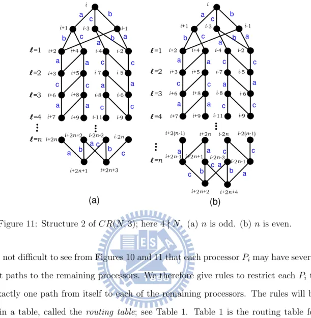
12, 14, . . . , 2010 (a total of 1000 N’s) and w = 3, 5, . . . , 21 (a total of 10 w’s). 19 10 Structure 1 of CR(N, 3); here 4 | N. (a) n is odd. (b) n is even. . . 20 11 Structure 2 of CR(N, 3); here 4 - N. (a) n is odd. (b) n is even. . . 21 12 (a) The chordal ring network CR(20, 3). (b) CR(20, 3) is of structure 1. . . 25 13 An illustration for case 2. . . 31
List of Tables
1 Routing table for Pi when i is even; if i is odd, then replace a-link by b-link
and replace b-link by a-link. . . 22 2 A table used to construct Table 1. Note that “final*” will be explained later. 22 3 Routing header for Pi when i is even; if i is odd, then replace a-link by
b-link and replace b-link by a-link. . . 24 4 Eleven forms of the routing headers. . . 24 5 The routing table with respected to P0 of CR(20, 3). Note that the
desti-nations of the last personalized messages sent out from P0 are P10, P9, P7 and P11. . . 24 6 The routing header for each processor (except Pi+1, Pi−1, and Pi−3, which
will use only one a-link or b-link or c-link) when CR(N, 3) is of structure 1, Pi is the source and i is even. . . 28
1
Introduction
Processors in a parallel and distributed processing system often need to communicate with other processors. The communication among these processors could be one-to-one, one-to-many, or all. All-to-all communication can be further classified into all-to-all broadcast and all-to-all-to-all-to-all personalized exchange. In all-to-all-to-all-to-all broadcast, each processor sends the same message to all other processors; while in all-to-all personalized exchange, each processor sends a specific message to every other processor.
All-to-all personalized exchange occurs in many important applications (for example, matrix transposition and fast Fourier transform (FFT)) in parallel and distributed com-puting. The all-to-all personalized exchange problem has been extensively studied for hypercubes, meshes, and tori; see [9] for details.
In [9], Yang and Wang considered fulfilling all-to-all personalized exchange on multi-stage interconnection networks. The purpose of this thesis is to consider fulfilling all-to-all personalized exchange in chordal ring networks. Graph terminologies and notations in this thesis are standard; see [3] and [8] except as indicated. All the graphs considered in this thesis are assumed simple. For convenience, vertices of a graph are also called nodes.
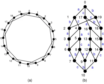
A chordal ring network CR(N, w), where N is a positive even integer and w is a positive odd integer and w ≤ N/2, is a graph with N nodes 0, 1, . . . , N − 1 and 3N/2 links of the forms:
ring-links: (i, (i + 1) mod N), i = 0, 1, 2, . . . , N − 1, chordal-links: (i, (i + w) mod N), i = 1, 3, 5, . . . , N − 1.
See Figure 1 for an example. Chordal ring networks were first proposed by Arden and Lee [1] and these networks can be viewed as adding chords to a ring network (a cycle).
In this thesis, each node in a chordal ring network has exactly three neighbors; some researchers call such a 3-regular chordal ring network a chordal ring network of degree 3. In this thesis, we consider chordal ring networks of degree 3. Do notice that some researchers considered chordal ring networks of degree 4 or degree 6 (in other words, each vertex has four or six neighbors); see [2]. Note that communication algorithms can
14 2 1 4 3 6 5 8 7 10 9 12 11 13 16 15 17 0
Figure 1: CR(18, 5): the chordal ring network with N = 18 and w = 5.
be implemented in a one-port model or a multi-port model. In a one-port model, only one incident link of a node can be used; however, in a multi-port model, more than one incident link of a node can be used simultaneously. In this thesis, we assume a multi-port model since a multi-port model can be simulated by a one-port model; this is also the model used in [5]. Further, the links in a chordal ring network can be either unidirectional or bidirectional. In this thesis, we follow the convention used in [5] that all the links in a chordal ring network are bidirectional. It is assumed that there are at most two faults in an all-to-all communication. We also assume that it takes one time unit to transmit a message from a node to an adjacent node.
In [5, 7], Masuyama et al. proposed two all-to-all personalized exchange algorithms for chordal ring networks of degree 3; for convenience, call these two algorithms Algorithm A and Algorithm B. Algorithm A is used when there is no fault. Algorithm B is used when at least one fault occurs. See also [6] for optical routing algorithms for chordal ring of degree 4. In this thesis, we consider the all-to-all personalized exchange problem in degree 3 chordal ring networks. Therefore, in the remaining discussions, unless other specified, a chordal ring network means a degree 3 chordal ring network.
The motivation of this thesis is as follows. In [5, 7], it has been proven that N
2 time
units can fulfill an all-to-all broadcast in a chordal ring network and PN2
can fulfill an all-to-all personalized exchange in a chordal ring network. However, we observe that Algorithm A only utilizes ring-links to fulfill an all-to-all communication and chordal-links are used only when there are faults. Since all of the chordal-links are not used in any all-to-all communication when there is no fault, a huge amount of hardware is wasted. In this thesis, we will use chordal-links to facilitate an all-to-all personalized exchange. In particular, we propose an all-to-all personalized exchange algorithm that works for all chordal ring networks; we will call it a general algorithm. We will use experimental results to show that our general algorithm uses less time units to fulfill an all-to-all personalized exchange and hence improves the previous algorithms in [5, 7]. We also provide an all-to-all personalized exchange algorithm that works only for chordal ring networks with w = 3; we will show that this algorithm makes a huge improvement for the previous algorithms in [5, 7].
When there is only one fault, Algorithm B has several unclear parts. In this thesis, we will clarify these unclear parts. When there are two faults, we will show that Algorithm B actually does not fulfill an all-to-all broadcast. In this thesis, we will point out why Algorithm B does not fulfill an all-to-all broadcast.
This thesis is organized as follows. Section 2 gives some preliminaries. Section 3 gives an algorithm for fulfilling all-to-all personalized exchange in a chordal ring network; this algorithm works for all chordal ring networks CR(N, w). Section 4 gives an algorithm for fulfilling all-to-all personalized exchange in chordal ring networks CR(N, w) with w = 3. In Section 5, we will point out the unclear parts and incorrect parts of Algorithm B, and we also correct Algorithm B. The concluding remarks are given in the last section.
2
Preliminaries
Recall that a chordal ring network CR(N, w) contains ring-links and chordal-links. We will follow the following definitions given in [5, 7]: R(i), R(i)start, R(i)end, and R(1)f.
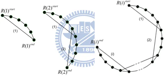
(1) Ring R(1) is a loop which is composed of one chordal-link (labeled by (1) in Figure 2), w ring-links bypassed by the chordal-links, and w+1 nodes.
(2) Ring R(2) is a loop which is composed of two chordal-links which have only one common ring-link bypassed by the two consecutive chordal-links (labeled by (1) and (2) in Figure 2), and 2w nodes, but does not include the common bypassed ring-link. (3) Ring R(i) is a loop which is composed of ring R(i−1) exclusive of a ring-link bypassed by the i-th additional new chordal-link (labeled by (i) in Figure 2), the additional new chordal-link, and w − 1 ring-links and nodes bypassed by the additional new chordal-link.
(4) Two nodes labels R(i)start and R(i)end on each loop R(i) are special marks that are
used to find the loop R(i). See Figure 2 for an example of R(i)start and R(i)end.
(1)start R (1)end R (1) (2)start R (2)end R (1) (2) (i) (1) (2) ( )end R i ( )start R i
Figure 2: R(1), R(2), and R(i) in the w = 5 case.
(5) Given a faulty node f , find a ring R(1) such that f is in the middle of R(1) and denote this R(1) by R(1)f. Make the longest non-faulty loop which is composed
of R(1)start, R(1)end, and all nodes except nodes on R(1)f, and denote this loop
by R(1)f. For example, in Figure 3, suppose the node depicted in color black is the faulty node. Then R(1)f is the loop 1, 2, 3, 4, 5, 6, 1 and R(1)f is the loop
1, 6, 7, 8, 9, 10, 11, 12, 13, 14, 15, 16, 17, 0, 1.
In the following, the notations h, k, and kp are used very often. We now define them.
(1)
fR
Figure 3: R(1)f.
source node and used by our algorithm. Further, k denotes the number of consecutive (ring-link, chordal-link) pairs used by our algorithm. Notice that h and kp require that
the ring-links start from a given source node. Also notice that k requires that a total of k (ring-link, chordal-link) pairs are used and in each pair of (ring-link, chordal-link), a ring-link is used before a chordal-link.
3
Main result–a general all-to-all personalized
ex-change algorithm
Recall that Masuyama et al. [5, 7] proposed an all-to-all personalized exchange algo-rithms for chordal ring network when there is no fault and we call it Algorithm A. This algorithm takes
N
2
P
i=1
i time units and this algorithm does not utilize any chordal-links. In this section, we will propose an all-to-all personalized exchange algorithm that utilizes both ring-links and chordal-links; since our algorithm works for all chordal ring networks, we also say that it is a general algorithm.
In the remaining discussion, a processor means a node in a given chordal ring net-work. Moreover, we assume that the indices of processors are taken modulo N; for
example, processor Pi+h+1is processor P(i+h+1) mod N and processor Pi+N −h−1 is processor
P(i+N −h−1) mod N. Our algorithm, Algorithm 1, is an algorithm for fulfilling an all-to-all personalized exchange in chordal ring networks. Algorithm 1 is divided into two parts: part 1 handles the h ≥ w case and part 2, the h < w case. For convenience, in Algorithm 1, the following terminologies are used:
route 1: a route via k (ring-link,chordal-link) pairs and kp ring-links;
route 2: a route via kp ring-links and k (ring-link, chordal-link) pairs;
route 3: a route via k (ring-link,chordal-link) pairs, kp ring-links, and 1 ring-link;
route 4: a route via kp ring-links, k (ring-link,chordal-link) pairs, and 1 ring-link;
route 5: a route via k (ring-link,chordal-link) pairs, 1 ring-link, and 1 chordal-link; route 6: a route via 1 chordal-link, k (ring-link,chordal-link) pairs, and 1 ring-link.
Algorithm 1 works as follows. All the processors P0, P1, . . . , PN −1 transmit their
mes-sages simultaneously. Each Pi first computes a value h and transmits a personalized
message to each processor which is within a distance h from Pi. After the above process,
Pi+1, Pi+2, . . . , Pi+h and also Pi−1, Pi−2, . . . , Pi−h have received a personalized message
from Pi; only Pi+h+1, Pi+h+2, . . . , Pi+N −h−1have not received a personalized message from
Pi yet. Then, according to whether h ≥ w or not, Algorithm 1 is divided into two parts.
Part 1 of Algorithm 1 (the h ≥ w case) works as follows. Each Pi computes the values
k and kp (note that kp is always less than or equal to w). According to the parity of h,
the h ≥ w case actually consists of two subcases. • Suppose h is even.
¦ Suppose kp < w.
If i is even (resp., odd), then Piwill use route 1 (resp., route 2) to arrive Pi+h+1
and use route 2 (resp., route 1) to arrive Pi+N −h−1. Once Pi can arrive Pi+h+1,
on; simultaneously, once Pican arrive Pi+N −h−1, it can transmit, via ring-links,
a personalized message to Pi+N −h−1, Pi+N −h−2, and so on.
¦ Suppose kp = w.
If i is even (resp., odd), then Pi will use route 5 (resp., route 6) to arrive
Pi+h+2 and use route 6 (resp., route 5) to arrive Pi+N −h−2. Once Pi can arrive
Pi+h+2, it can transmit, via a ring-link, a personalized message to Pi+h+1;
simultaneously, once Pi can arrive Pi+N −h−2, it can transmit, via a ring-link,
a personalized message to Pi+N −h−1. Also, once Pi can arrive Pi+h+2, it can
transmit, via ring-links, a personalized message to Pi+h+2, Pi+h+3, and so on;
simultaneously, once Pi can arrive Pi+N −h−2, it can transmit, via ring-links, a
personalized message to Pi+N −h−2, Pi+N −h−3, and so on.
• Suppose h is odd. ¦ Suppose kp < w.
If i is even (resp., odd), then Piwill use route 3 (resp., route 4) to arrive Pi+h+1
and use route 4 (resp., route 3) to arrive Pi+N −h−1. Once Pi can arrive Pi+h+1,
it can transmit, via ring-links, a personalized message to Pi+h+1, Pi+h+2, and so
on; simultaneously, once Pican arrive Pi+N −h−1, it can transmit, via ring-links,
a personalized message to Pi+N −h−1, Pi+N −h−2, and so on.
¦ Suppose kp = w.
If i is even (resp., odd), then Piwill use route 5 (resp., route 6) to arrive Pi+h+1
and use route 6 (resp., route 5) to arrive Pi+N −h−1. Once Pi can arrive Pi+h+1,
it can transmit, via ring-links, a personalized message to Pi+h+1, Pi+h+2, and so
on; simultaneously, once Pican arrive Pi+N −h−1, it can transmit, via ring-links,
a personalized message to Pi+N −h−1, Pi+N −h−2, and so on.
Part 2 of Algorithm 1 (the h < w case) works as follows. In a chordal ring network, N ≥ 2w always holds. According to whether N = 2w, the h < w case is divided into two subcases.
• Suppose N = 2w. ¦ Suppose i is even.
Then Pi will use a chordal-link to arrive Pi−w and use 1 ring-link plus 1
chordal-link to arrive Pi+1+w (i.e., Pi arrives Pi+1+w via Pi+1). Once Pi can arrive Pi−w,
it can transmit, via ring-links, a personalized message to Pi−w, Pi−w−1, . . . , Pi+h+1;
simultaneously, once Pi can arrive Pi+1+w, it can transmit, via ring-links, a
per-sonalized message to Pi+1+w, Pi+1+w+1, . . . , Pi+N −h−1.
¦ Suppose i is odd.
Then Pi will use a chordal-link to arrive Pi+w and use 1 ring-link plus 1
chordal-link to arrive Pi−1−w (i.e., Pi arrives Pi−1−w via Pi−1). Once Pi can arrive Pi+w,
it can transmit, via ring-links, a personalized message to Pi+w, Pi+w+1, . . . ,
Pi+N −h−1; simultaneously, once Pi can arrive Pi−1−w, it can transmit, via
ring-links, a personalized message to Pi−1−w, Pi−1−w−1, . . . , Pi+h+1.
• Suppose N ≥ 2w + 2. ¦ Suppose i is even.
Then Pi will use a chordal-link to arrive Pi−w and use 1 ring-link plus 1
chordal-link to arrive Pi+1+w (i.e., Pi arrives Pi+1+w via Pi+1). Once Pi can arrive Pi−w,
it can transmit, via ring-links, a personalized message to Pi−w, Pi−w+1, . . . ,
Pi+N −h−1 (in a clockwise fashion) and also to Pi−w−1, Pi−w−2, and so on (in
a counterclockwise fashion); simultaneously, once Pi can arrive Pi+1+w, it can
transmit, via ring-links, a personalized message to Pi+1+w, Pi+1+w−1, . . . , Pi+h+1
(in a counterclockwise fashion) and also to Pi+1+w+1, Pi+1+w+2, and so on (in
a clockwise fashion). ¦ Suppose i is odd.
Then Pi will use a chordal-link to arrive Pi+w and use 1 ring-link plus 1
chordal-link to arrive Pi−1−w (i.e., Pi arrives Pi−1−w via Pi−1). Once Pi can arrive Pi+w,
Pi+h+1 (in a counterclockwise fashion) and also to Pi+w+1, Pi+w+2, and so on
(in a clockwise fashion); simultaneously, once Pi can arrive Pi−1−w, it can
trans-mit, via ring-links, a personalized message to Pi−1−w, Pi−1−w+1, . . . , Pi+N −h−1
(in a clockwise fashion) and also to Pi−1−w−1, Pi−1−w−2, and so on (in a
coun-terclockwise fashion).
The following is the outline of Algorithm 1.
Algorithm 1:
part 1: the h ≥ w case h is even ( kp < w (case 1a) kp = w (case 1b) h is odd ( kp < w (case 1c) kp = w (case 1d)
part 2: the h < w case (
N = 2w (case 2a) N ≥ 2w + 2 (case 2b) Now we are ready to present Algorithm 1.
Algorithm 1 All-to-all personalized exchange algorithm for chordal ring networks. Input: A chordal ring network CR(N, w).
Output: All-to-all personalized exchange of CR(N, w). 1: for each Pi (0 ≤ i ≤ N − 1) do in parallel
2: h ← b3396Nc; 3: for j = 1 to h do
4: Pi prepares personalize messages for Pi+j and Pi−j;
5: Pi transmits personalize messages to Pi+j and Pi−j via ring-links;
6: endfor
7: if h < w then goto part 2; endif 8: part 1: 9: k ← bh+1 w+1c; 10: kp ← h + 1 − k(w + 1); 11: a ← h + 1; 12: b ← N − h − 1; 13: if h is even then 14: if kp < w then 15: for j = 0 to dN −2h−3 2 e do 16: if i is even then
17: Pi transmits personalize messages to Pi+j+a via route 1 and j ring-links
18: and to Pi−j+b via route 2 and j ring-links;
19: else /∗ i is odd ∗/
20: Pi transmits personalize messages to Pi+j+a via route 2 and j ring-links
21: and to Pi−j+b via route 1 and j ring-links;
22: endif
23: endfor
24: else /∗ kp = w ∗/
25: Pi transmits personalize messages to Pi+a+1 via route 5 and 1 ring-links
26: to Pi+a and to Pi+b−1 via route 6 and 1 ring-links to Pi+b;
27: for j = 0 to dN −2h−5
2 e do
28: if i is even then
29: Pi transmits personalize messages to Pi+j+a+1 via route 5 and j ring-links
30: and to Pi−j+b−1 via route 6 and j ring-links;
31: else /∗ i is odd ∗/
32: Pi transmits personalize messages to Pi+j+a+1 via route 6 and j ring-links
33: and to Pi−j+b−1 via route 5 and j ring-links;
34: endif 35: endfor 36: endif 37: else /∗ h is odd ∗/ 38: if kp < w then 39: for j = 0 to dN −2h−3 2 e do 40: if i is even then
41: Pi transmits personalize messages to Pi+j+a via route 3 and j ring-links
42: and to Pi−j+b via route 4 and j ring-links;
43: else
44: Pi transmits personalize messages to Pi+j+a via route 4 and j ring-links
46: endif 47: endfor 48: endif 49: else /∗ kp = w ∗/ 50: for j = 0 to dN −2h−32 e do 51: if i is even then
52: Pi transmits personalize messages to Pi+j+a via route 5 and j ring-links
53: and to Pi−j+b via route 6 and j ring-links;
54: else /∗ i is odd ∗/
55: Pi transmits personalize messages to Pi+j+a via route 6 and j ring-links
56: and to Pi−j+b via route 5 and j ring-links;
57: endif
58: endfor
59: endif
60: stop the algorithm
61: part 2:
62: c ← i − w; d ← i + w; 63: if N = 2w then;
64: for j = 0 to dN −2h−32 e do
65: if i is even then
66: Pi transmits personalize messages to Pc−j via 1 chordal-link and j ring-links,
67: and to P1+d+j via Pi+1, 1 chordal-link, and j ring-links;
68: else /* i is odd */
69: Pi transmits personalize messages to Pd+j via 1 chordal-link and j ring-links,
70: and to Pc−1−j via Pi−1, 1 chordal-link, and j ring-links;
71: endif
72: endfor
73: else /* N ≥ 2w + 2 */ 74: for j = 0 to w − h + 1 do
75: if i is even then
76: Pi transmits personalize messages to Pc+j via 1 chordal-link and j ring-links,
77: and to P1+d−j via Pi+1, 1 chordal-link, and j ring-links;
78: else /* i is odd */
79: Pi transmits personalize messages to Pd−j via 1 chordal-link and j ring-links,
80: and to Pc−1+j via Pi−1, 1 chordal-link, and j ring-links;
81: endif
82: endfor
83: for j = 0 to N −2w−22 do
84: if i is even then
85: Pi transmits personalize messages to Pc−j via 1 chordal-link and j ring-links,
86: and to P1+d+j via Pi+1, 1 chordal-link, and j ring-links;
87: else /* i is odd */
88: Pi transmits personalize messages to Pd+j via 1 chordal-link and j ring-links,
89: and to Pc−1−j via Pi−1, 1 chordal-link, and j ring-links;
90: endif
91: endfor
Before going further, we give two remarks of Algorithm 1.
Remark 1. When a personalized message is sent from Pi to Pj, we try to utilize as
many (ring-link, chordal-link) pairs as possible; k is the maximum number of such (ring-link, chordal-link) pairs.
Remark 2. When a personalized message is sent from Pito Pj, k (ring-link, chordal-link)
pairs may not make Pi arrive Pj; kp ring-links are used to make Pi arrive Pj.
We now give six examples for Algorithm 1.
Example 1. Consider CR(24, 5). Then h = 8. Since h ≥ w, part 1 is executed and k = 1, kp = 3. So case 1a occurs. Figure 4(a) shows the general situation of case 1a
with P0being the source of personalized messages. Figure 4(b) shows the situation of CR(24, 5) with P0being the source of personalized messages. Figure 4(b) shows that by using Algorithm 1, P0can transmit personalized messages to all other processors. In particular, the lines depicted as color black represent the k (ring-link,chordal-link) pairs, and the lines depicted as color grey represent the kp ring-links. Thus after
executing lines 3 to 6, P0 transmits personalized messages to P1, P2, . . . , P8 and also
to P23, P22, . . . , P16. After executing lines 15 to 23, P0 utilizes route 1 to arrive P9
and route 2 to arrive P15; so P0 transmits personalized messages to P9, P10, P11, P12 and also to P15, P14, P13, P12.
Example 2. Consider CR(20, 3). Then h = 6. Since h ≥ w, part 1 is executed and k = 1. So case 1b occurs. Figure 5(a) shows the general situation of case 1b with P0 being the source of personalized messages. Figure 5(b) shows the situation of CR(20, 3) with P0 being the source of personalized messages. Figure 5(b) shows that by using Algorithm 1, P0 can transmit personalized messages to all other processors. In particular, the lines depicted as color black represent the k (ring-link,chordal-link) pairs, the lines depicted as color grey represent the additional one ring-link, and the lines depicted as dashed represent the w. Thus after executing lines 3 to 6, P0 transmits personalized messages to P1, P2, . . . , P6, and also to P19, P18, . . . , P14.
(a)
N-h -1 h +1
(b)
Figure 4: (a) The general situation of case 1a. (b) The situation of case 1a for CR(24, 5).
After executing lines 25 to 35, P0 utilizes route 5 to arrive P8 and route 6 to arrive P12; so P0 transmits personalized messages to P8, P9, P10, and also to P12, P11, P10. Finally P0 transmits personalized messages to P7, P13.
(a)
0
(b)
Figure 5: (a) The general situation of case 1b. (b) The situation of case 1b for CR(20, 3).
Example 3. Consider CR(22, 5). Then h = 7. Since h ≥ w, part 1 is executed and k = 1, kp = 1. So case 1c occurs. Figure 6(a) shows the situation of CR(22, 5)
with P0 being the source of personalized messages. Figure 6(a) shows that by using Algorithm 1, P0 can transmit personalized messages to all other processors. In particular, the lines depicted as color black represent the k (ring-link,chordal-link) pairs, the line depicted as color grey represent the kp ring-links, and last the line
depicted as color grey represent additional ring-link. Thus after executing lines 3 to 6, P0 transmits personalized messages to P1, P2, . . . , P7, and also to P21, P20, . . . , P15. After executing lines 38 to 48, P0 utilizes route 3 to arrive P8 and route 4 to arrive P14; so P0 transmits personalized messages to P9, P10, P11, and also to P13, P12, P11. Example 4. Consider CR(22, 3). Then h = 7. Since h ≥ w, part 1 is executed and k = 1. So case 1d occurs. Figure 6(b) shows the situation of CR(22, 3) with P0 being the source of personalized messages. Figure 6(b) shows that by using Algorithm 1, P0 can transmit personalized messages to all other processors. In particular, the lines depicted as color black represent the k (ring-link,chordal-link) pairs, the lines depicted as color grey represent the additional one ring-link, and the lines depicted as dashed represent the w. Thus after executing lines 3 to 6, P0 transmits personalized messages to P1, P2, . . . , P7, and also to P21, P20, . . . , P15. After executing lines 49 to 59, P0 utilizes route 5 to arrive P8 and route 6 to arrive P14; so P0 transmits personalized messages to P9, P10, P11, and also to P13, P12, P11. Example 5. Consider CR(18, 9). Then h = 6. Since h < w, part 2 is executed. So case 2a occurs. Figure 7(a) shows the situation of CR(18, 9) with P0 being the source of personalized messages. Figure 7(a) shows that by using Algorithm 1, P0 can transmit personalized messages to all other processors. In particular, the lines depicted as color black represent P0 will arrive to two main processors, P9 and P10. Thus after executing lines 3 to 6, P0 transmits personalized messages to P1, P2, . . . , P6, and also to P17, P16, . . . , P12. After executing lines 64 to 72, P0utilizes a chordal-link to arrive P9 and and use 1 ring-link plus 1 chordal-link to arrive P10. so P0 transmits personalized messages to P9, P8, P7; and also to P10, P11.
(a)
(b)
Figure 6: (a) The situation of case 1c for CR(22, 5). (b) Case 1d for CR(22, 3).
Example 6. Consider CR(20, 7). Then h = 6. Since h < w, part 2 is executed. So case 2b occurs. Figure 7(b) shows the situation of CR(18, 9) with P0 being the source of personalized messages. Figure 7(b) shows that by using Algorithm 1, P0 can transmit personalized messages to all other processors. In particular, the lines depicted as color black represent P0 will arrive to two main processors, P8 and P13. Thus after executing lines 3 to 6, P0 transmits personalized messages to P1, P2, . . . , P6, and also to P19, P18, . . . , P14. After executing lines 74 to 91, P0utilizes a chordal-link to arrive P8 and and use 1 ring-link plus 1 chordal-link to arrive P13. so P0 transmits personalized messages to P7, P9, P10; and also to P13, P12, P11, P10. We now prove the correctness of Algorithm 1.
Theorem 1. Algorithm 1 fulfills an all-to-all personalized exchange for CR(N, w). Proof. It suffices to prove that each processor receives a personalized message from Pi,
where 0 ≤ i ≤ N − 1. Let Pj be a processor of CR(N, w) such that j 6= i. If j ∈
{i + 1, i + 2, . . . , i + h, i − 1, i − 2, . . . , i + N − h}, then Pj receives a personalized message
from Pi after lines 3 to 6 are executed. For the h ≥ w case, if j ∈ {i + h + 1, i + h +
(a) (b)
Figure 7: (a) The situation of case 2a for CR(18, 9). (b) Case 2b for CR(20, 7).
Algorithm 1 is executed; these personalized messages are from routes 1, 2, 3, or 4. On the other hand, if h < w, then part 2 of Algorithm 1 is executed. Let Pj be a processor of
CR(N, w) such that j 6= i. If j ∈ {i + 1, i + 2, . . . , i + h, i − 1, i − 2, . . . , i + N − h}, then Pj receives a personalized message from Pi after lines 3 to 6 are executed. If N = 2w and
j ∈ {i + h + 1, i + h + 2, . . . , i + N − h − 1}, then Pj receives a personalized message from Pi
after lines 64 to 72 are executed. If N ≥ 2w+2 and j ∈ {i+h+1, i+h+2, . . . , i+N −h−1}, then Pj receives a personalized message from Pi after lines 74 to 91 are executed.
We now analyze the time complexity of Algorithm 1.
Theorem 2. For CR(N, w), Algorithm 1 takes t time units, where
t= h(h+1) 2 + (h0+1)(8k+4k p+h0−1) 8 if case 1a occurs, h(h+1) 2 + (h0−1)(8k+h0+5) 8 + 2k + 3 if case 1b occurs, h(h+1) 2 + (h0−1)(8k+4k p+h0−1) 8 if case 1c occurs, h(h+1) 2 + (h0+1)(8k+4kp+h0+3) 8 if case 1d occurs, h(h+1) 2 + (N −w−h)(N −w−h+1) 2 if case 2a occurs, h(h+1) 2 + (w−h+4)(w−h+1) 2 + (N −2w+8)(N −2w−2) 8 if case 2b occurs, in which h0 = N − 1 − 2h.
message to each node which is within a distance h from i. This process spends Ph
i=1
i time units. After the above process, h0 = N − 1 − 2h processors have not receive a personalized
message from Pi. If Pi sends messages to the remaining h0 processors by using case 1a
(lines 15 to 23), then t = Ph i=1 i + ³h0−1 2 P i=0 (2k + kp+ i) ´ = h(h+1)2 +(h0+1)(8k+4kp+h0−1) 8 .
If Pi sends messages to the remaining h0 processors by using case 1b (lines 25 to 35), then
t = Ph i=1 i + ³h0−3 2 P i=0 (2k + 2 + i) ´ + (2k + 3) = h(h+1)2 +(h0−1)(8k+h8 0+5) + 2k + 3.
If Pi sends messages to the remaining h0 processors by using case 1b (lines 38 to 48), then
t = Ph i=1 i + ³h0−1 2 P i=0 (2k + kp + 1 + i) ´ = h(h+1)2 +(h0−1)(8k+4kp+h0−1) 8 .
If Pi sends messages to the remaining h0 processors by using case 1b (lines 49 to 59), then
t = Ph i=1 i + h0−1 2 P i=0 (2k + 2 + i) = h(h+1)2 +(h0+1)(8k+4kp+h0+3) 8 .
If Pi sends messages to the remaining h0 processors by using case 1b (lines 64 to 72), then
t = Ph
i=1
i +N −w−hP
i=1
i = h(h+1)2 +(N −w−h)(N −w−h+1)2 .
If Pi sends messages to the remaining h0 processors by using case 1b (lines 74 to 91), then
t = Ph i=1 i + ³w−h+1P i=1 (i + 1) ´ + ³N −2w−2 2 P i=1 (2 + i) ´ = h(h+1)2 +(w−h+4)(w−h+1)2 +(N −2w+8)(N −2w−2)8 .
Before ending this section, we compare our algorithm with Algorithm A. Recall that Algorithm A takesPN2
i=1i time units. On the other hand, our algorithm takes only t time
units, where t is given in Theorem 2. Therefore, for a given CR(N, w), the percentage of improvements of our algorithm is
³ PN 2 i=1i ´ − t PN 2 i . (1)
In Appendix A, we list the percentage of improvements of our algorithm for N = 12, 14, . . . , 2010 (a total of 1000 N’s and a total of 252000 chordal ring networks). In this appendix, N and w are the parameters of CR(N, w), tour is the number of time units
used by Algorithm 1, tA is the number of time units used by Algorithm A, and % is the
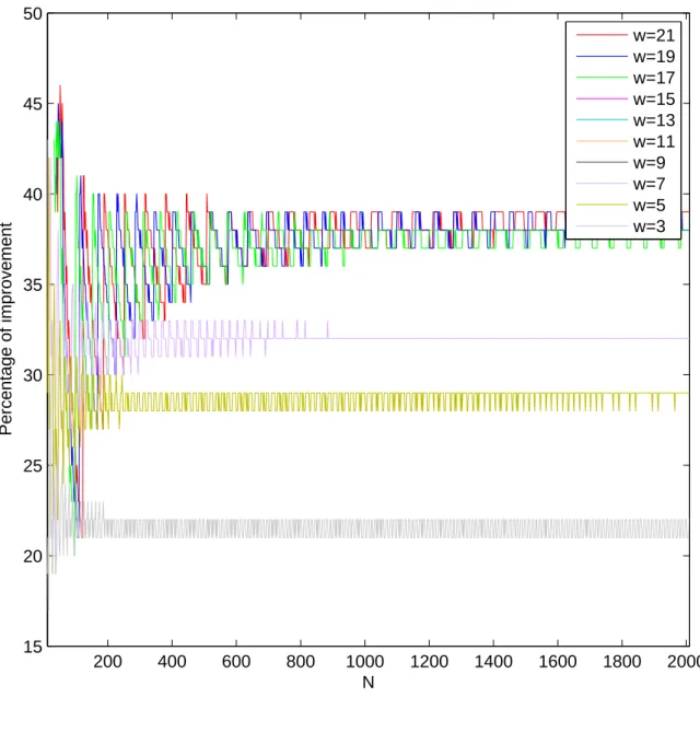
percentage of improvements of Algorithm 1, which is calculated by (1). See Figure 8 for the curve and Figure 9 for the pie chart of the percentage of improvements of Algorithm 1.
200 400 600 800 1000 1200 1400 1600 1800 2000 15 20 25 30 35 40 45 50 N Percentage of improvement w=21 w=19 w=17 w=15 w=13 w=11 w=9 w=7 w=5 w=3
Figure 8: The percentage of improvements of Algorithm 1 for N = 12, 14, . . . , 2010 (a total of 1000 N’s) and w = 3, 5, . . . , 21 (a total of 10 w’s).
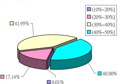
ʻ˅˃ʸ̑ˆ˃ʸ˰ ˇˆ˄ˌˈ ʻˆ˃ʸ̑ˇ˃ʸ˰ ˄˃ˈˊ˄ˈ ʻˇ˃ʸ̑ˈ˃ʸ˰ ˄˃ˆ˃ˊˇ ˇ˃ˁˌ˃ʸ ˃ˁ˃˄ʸ ˄ˊˁ˄ˇʸ ˇ˄ˁˌˈʸ ʻ˄˃ʸ̑˅˃ʸ˰ ʻ˅˃ʸ̑ˆ˃ʸ˰ ʻˆ˃ʸ̑ˇ˃ʸ˰ ʻˇ˃ʸ̑ˈ˃ʸ˰
Figure 9: The pie chart of the percentage of improvements of Algorithm 1 for N = 12, 14, . . . , 2010 (a total of 1000 N’s) and w = 3, 5, . . . , 21 (a total of 10 w’s).
According to Figure 8, we find that the percentage of improvements of Algorithm 1 becomes better as w increases. Moreover, for each w, the curve of CR(N, w) oscillates very seriously when when N varies from 12 to 200, and the curve has its period of oscillation when N > 200. Finally, the curve becomes smooth and approaches to a fixed value.
According to Figure 9, among the 252000 chordal ring networks, 40.90% of them get an improvement of at least 40%; 41.95% of them get an improvement of at least 30% and less than 40%; about 41.95% of them get an improvement of at least 30% but less than 40%; 17.14% of them get an improvement of at least 20% but less than 30%; and 0.01% of them get an improvement of at least 10% but less than 20%.
4
A special all-to-all personalized exchange algorithm
for CR(N, w) with w = 3
From Figure 8, we know that Algorithm 1 has the lowest percentage of improvements when w = 3. Therefore, in this section, we will design an all-to-all personalized exchange algorithm for chordal ring networks CR(N, w) with N ≥ 10 and w = 3. We find that when N ≥ 10, CR(N, 3) has a very nice structure and we make use of this nice structure to design a all-to-all personalized exchange algorithm, called Algorithm 2, such that the
percentage of improvements of this algorithm is at least 50%.
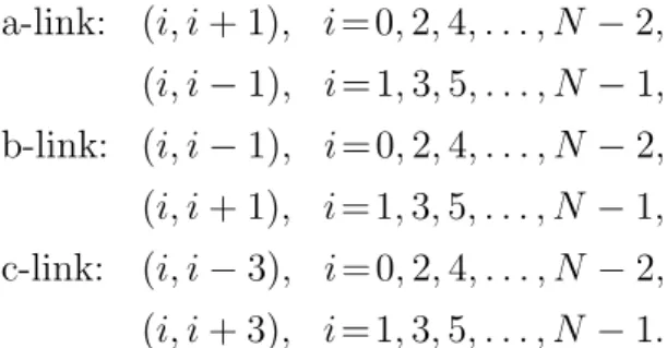
To describe Algorithm 2, we define three types of links. Recall that we assume that the indices of processors are taken modulo N.
Definition : The links of CR(N, 3) is divided into three categories. a-link: (i, i + 1), i = 0, 2, 4, . . . , N − 2, (i, i − 1), i = 1, 3, 5, . . . , N − 1, b-link: (i, i − 1), i = 0, 2, 4, . . . , N − 2, (i, i + 1), i = 1, 3, 5, . . . , N − 1, c-link: (i, i − 3), i = 0, 2, 4, . . . , N − 2, (i, i + 3), i = 1, 3, 5, . . . , N − 1.
We now give the structure of CR(N, 3). We observe that CR(N, 3) has only two possible structures, depending on whether N is divisible by 4. If 4 | N, we call the structure structure 1 and if 4 - N, we call the structure structure 2. For convenience, we use n to denote the number of layers which have exactly 4 nodes in structures 1 or 2 and we use L to denote the set of processors that appear in these n layers. See Figures 10 and 11; in these figures, a, b and c represent a-link, b-link and c-link, respectively.
(a) (b) A=1 A=2 A=3 A=4 A=n i i- 2n i- 2n-2 i+ 2n+ 2 i+ 2n i+ 2n+ 3 i- 2n-3 i+ 2n+ 1 i- 9 i- 6 i- 5 i- 2 i- 11 i- 8 i- 7 i- 4 i+ 9 i+ 8 i+ 5 i+ 4 i+ 7 i+ 6 i+ 3 i+ 2 i- 3 i- 1 i+ 1 b b b b a b a a a a a a a a a c a c c c c c c c c c c c b a i+ 2n+ 4 A=n A=4 A=3 A=2 A=1 a b c c c c c c c c a c a a a a a a b b a i+ 1 i- 3 i- 1 i+ 2 i+ 3 i+ 6 i+ 7 i+ 4 i+ 5 i+ 8 i+ 9 i- 4 i- 7 i- 8 i- 11 i- 2 i- 5 i- 6 i- 9 i i- 2(n- 1) i- 2n i+ 2n i+ 2(n- 1) i- 2n- 1 i- 2n- 3 i+ 2n+ 1 i+ 2n- 1 a a c c c c a a b b i- 2n- 2 i+ 2n+ 4 i+ 2n+ 2 i+ 2n+ 3 c a b
(b) (a) A=4 A=3 A=n A=2 A=1 i i+ 2n+3 i+ 2n+1 i+ 2n i+ 2n+2 i- 2n-2 i- 2n i- 4 i- 7 i- 8 i- 11 i- 9 i- 6 i- 5 i- 2 i+ 4 i+ 5 i+ 8 i+ 9 i+ 2 i+ 3 i+ 6 i+ 7 i- 1 i- 3 i+ 1 b b b b a a a a a a a a a a c c c c c c c c c c b a b b a a a a c c c c i+ 2n-1 i+2n+1 i- 2n-3 i- 2n-1 i+ 2(n-1) i+ 2n i- 2n i- 2(n-1) i i- 4 i- 7 i- 8 i- 11 i- 9 i- 6 i- 5 i- 2 i+ 4 i+ 5 i+ 8 i+ 9 i+ 2 i+ 3 i+ 6 i+ 7 i- 1 i- 3 i+ 1 b b a a a a a a a a c c c c c c c c b a A=n A=4 A=3 A=2 A=1 i+ 2n+2 i+ 2n+4 i
Figure 11: Structure 2 of CR(N, 3); here 4 - N. (a) n is odd. (b) n is even.
It is not difficult to see from Figures 10 and 11 that each processor Pi may have several
shortest paths to the remaining processors. We therefore give rules to restrict each Pi to
have exactly one path from itself to each of the remaining processors. The rules will be stored in a table, called the routing table; see Table 1. Table 1 is the routing table for CR(N, 3) with Pi as the source of all personalized messages. In Table 1, the numbers
1, 2, 3, . . . represent the time unit; the notation “j; k” means that a personalized message for Pj is sent out from Pi and the next personalized message sent out from Pi through
the same link is after k time units; the notation “−” means that Pi does not send out
a personalized message by itself but Pi may help with transmitting another processor’s
personalized message.
Our all-to-all personalized exchange algorithm for chordal ring networks CR(N, w) with w = 3 will use as its routing table to send out the messages; see Algorithm 2.
Table 1: Routing table for Pi when i is even; if i is odd, then replace a-link by b-link and
replace b-link by a-link.
(i) CR(N, 3) is of structure 1 and n is odd
1 2 3 4 5 6 7 8 9 10 11 12 13 14 15 16 tp+1
a i + 1 i + 4 − − i + 5 − − − − i + 8 − − − − − − − i + 2n + 3 −
b i − 1 i + 2 i − 2; 1 − i + 3 i − 5; 3 − − − i + 6 i − 6; 5 − − − − − . . . i + 2n + 4 i + 2n + 1 i − 2n − 3 . . .
c i − 3 i − 4 − − i − 7 − − − − i − 8 − − − − − − − − −
(ii) CR(N, 3) is of structure 1 and n is even
1 2 3 4 5 6 7 8 9 10 11 12 13 14 15 16 tp+1
a i + 1 i + 4 − − i + 5 − − − − i + 8 − − − − − − − i + 2n + 4 −
b i − 1 i + 2 i − 2; 1 − i + 3 i − 5; 3 − − − i + 6 i − 6; 5 − − − − − . . . i + 2n + 3 i + 2n + 2 i − 2n − 2 . . .
c i − 3 i − 4 − − i − 7 − − − − i − 8 − − − − − − − − −
(iii) CR(N, 3) is of structure 2 and n is odd
1 2 3 4 5 6 7 8 9 10 11 12 13 14 15 16 tp+1− 2
a i + 1 i + 4 − − i + 5 − − − − i + 8 − − − − − − − − −
b i − 1 i + 2 i − 2; 1 − i + 3 i − 5; 3 − − − i + 6 i − 6; 5 − − − − − . . . − i + 2n + 1 i + 2n + 3 . . .
c i − 3 i − 4 − − i − 7 − − − − i − 8 − − − − − − − − −
(iv) CR(N, 3) is of structure 2 and n is even
1 2 3 4 5 6 7 8 9 10 11 12 13 14 15 16 tp+1− 2
a i + 1 i + 4 − − i + 5 − − − − i + 8 − − − − − − − − −
b i − 1 i + 2 i − 2; 1 − i + 3 i − 5; 3 − − − i + 6 i − 6; 5 − − − − − . . . − i + 2n + 2 i + 2n + 4 . . .
c i − 3 i − 4 − − i − 7 − − − − i − 8 − − − − − − − − −
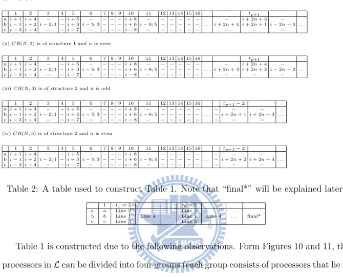
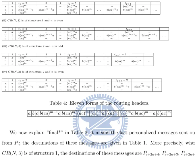
Table 2: A table used to construct Table 1. Note that “final*” will be explained later.
1 t1= 2 t2= 5
a a Line 2 Line 2
b b Line 1 Line 4 . . . Line 1 Line 4 . . . final*
c c Line 3 Line 3
Table 1 is constructed due to the following observations. Form Figures 10 and 11, the processors in L can be divided into four groups (each group consists of processors that lie in the same vertical line) and we call them Line 1, Line 2, Line 3 and Line 4. More precisely, Line 1 consists of Pi+2, Pi+3, Pi+6, and so on; Line 2 consists of Pi+4, Pi+5, Pi+8, and so on;
Line 3 consists of Pi−4, Pi−7, Pi−8 and so on; and Line 4 consists of Pi−2, Pi−5, Pi−6, and
so on. Notice that Pi has only three links; hence Pi can only send personalized messages
to processors in three of the four lines.
Table 1 is constructed according to Table 2, which suggests processors on which lines of the four lines are selected. More precisely, in time unit 1, Pi transmits personalized
Algorithm 2 All-to-all personalized exchange algorithm for CR(N, 3), where N ≥ 10. Input: A chordal ring network CR(N, 3), where N ≥ 10.
Output: All-to-all personalized exchange of CR(N, 3). 1: for Pi (0 ≤ i ≤ N − 1) do in parallel
2: Pi transmits personalize messages according to its routing table.
messages to Pi+1, Pi−1 and Pi−3. Started from time unit 2, Pi transmits personalized
messages according to Table 2. Table 2 says that at time unit 2, Pi transmits personalized
messages to a processor on Line 2, a processor on Line 1 and a processor on Line 3; at the next time unit, Pi transmits a personalized message to a processor on Line 4; at time
unit 5, Pi transmits personalized messages to a processor on Line 2, a processor on Line 1
and a processor on Line 3; at the next time unit, Pi transmits a personalized message to
a processor on Line 4. In general, at time unit tp, Pi transmits personalized messages to a
processor on Line 2, a processor on Line 1 and a processor on Line 3, and at the next time unit, Pi transmits a personalized message to a processor on Line 4. Here tp = tp−1+ wp,
where wp = 2 × (p − 1) + 1, t0 = 1, and 1 ≤ p ≤ n.
We assume that when a personalized message is sent out, a routing header is attached with the message and is used for routing the message. For example, b(ac)2a means that the routing path is via a b-link, then 2 pairs of (a-link,c-link), and 1 a-link. When a message is sent out from a processor, the first character of the routing header will be used in selecting the link used for sending the message; this character will be discarded then. Table 3 gives the routing headers for CR(N, 3) with Pi as the source of all personalized
messages.
From Table 3, we know that there are only eleven possible forms for the routing headers. We now summarize them in Table 4 and give a binary notation for each of them.
Table 3: Routing header for Pi when i is even; if i is odd, then replace a-link by b-link
and replace b-link by a-link.
(i) CR(N, 3) is of structure 1 and n is odd
1 t1= 2 3 4 t2= 5 tp+1
a a (ac)m − − (ac)ma − − (ac)ma −
b b b(ca)m−1c b(ac)m−1a − b(ca)m b(ac)m . . . b(ca)mc b(ca)m b(ac)m . . .
c c (ca)m − − (ca)mc − − − −
(ii) CR(N, 3) is of structure 1 and n is even
1 t1= 2 3 4 t2= 5 tp+1
a a (ac)m − − (ac)ma − − (ac)m −
b b b(ca)m−1c b(ac)m−1a − b(ca)m b(ac)m . . . b(ca)m b(ca)m−1c b(ac)m−1c . . .
c c (ca)m − − (ca)mc − − − −
(iii) CR(N, 3) is of structure 2 and n is odd
1 t1= 2 3 4 t2= 5 tp+1− 2
a a (ac)m − − (ac)ma − − − −
b b b(ca)m−1c b(ac)m−1a − b(ca)m b(ac)m . . . − b(ca)m b(ac)m . . .
c c (ca)m − − (ca)mc − − − −
(iv) CR(N, 3) is of structure 2 and n is even
1 t1= 2 3 4 t2= 5 tp+1− 2
a a (ac)m − − (ac)ma − − − −
b b b(ca)m−1c b(ac)m−1a − b(ca)m b(ac)m . . . − b(ca)m−1c b(ac)m−1a . . .
c c (ca)m − − (ca)mc − − − −
Table 4: Eleven forms of the routing headers.
a b c b(ca)m−1c b(ca)m (ac)m (ac)ma (ca)m (ca)mc b(ac)m−1a b(ac)m
We now explain “final*” in Table 2; it means the last personalized messages sent out from Pi; the destinations of these messages are given in Table 1. More precisely, when
CR(N, 3) is of structure 1, the destinations of these messages are Pi+2n+4, Pi+2n+3, Pi+2n+1
and Pi−2n−3 if n is odd; the destinations are Pi+2n+3, Pi+2n+4, Pi+2n+2 and Pi−2n−2 if n
is even. When CR(N, 3) is of structure 2, the destinations of these messages are Pi+2n+1
and Pi+2n+3 if n is odd; the destinations are Pi+2n+2 and Pi+2n+4 if n is even.
Table 5: The routing table with respected to P0 of CR(20, 3). Note that the destinations of the last personalized messages sent out from P0 are P10, P9, P7 and P11.
1 2 3 4 5 6 7 8 9 10 11 12 13 14 15 16 17 18 19 20 21 22 23 24 25
a 1 4 − − 5 − − − − 8 − − − − − − 9 − − − − − − − −
b 19 2 18;1 − 3 15;3 − − − 6 14;5 − − − − 10 7 11 − − − − − − −
c 17 16 − − 13 − − − − 12 − − − − − − − − − − − − − − −
Example. Consider CR(20, 3). It is of structure 1 and we illustrate its structure in Figure 12. Table 5 is the routing table with P0 being the source node. According to Table 5, at time unit 1, P0 sends personalized messages to P1 via its a-link, to P19 via
0 9 11 7 10 14 15 18 12 13 16 8 5 4 6 3 2 17 19 1 b b b b a b a a a a a a a c a c c c c c c c c c b a (a) (b) 19 18 17 16 15 14 13 12 11 10 9 8 7 6 5 4 3 2 1 0
Figure 12: (a) The chordal ring network CR(20, 3). (b) CR(20, 3) is of structure 1.
its b-link and to P17 via its c-link. At time unit 2, P0 sends personalized messages to P4 via its a-link, to P2 via its b-link and to P16 via its c-link. At time unit 3, P0 only sends a personalized message out to P18 via its b-link; at the same time unit, P0 helps with transmitting personalized messages of other processors to their destinations. Similarly, at time unit 5, P0 sends personalized messages to P5 via its a-link, to P3 via its b-link and to P13 via its c-link. At time unit 6, P0 only sends a personalized message out to P15 via its b-link; at the same time, P0 helps with transmitting personalized messages of other processors to their destinations.
Let n be the number of layers in CR(N, 3), where N ≥ 10. By Figures 10 and Figure 11, we know that if CR(N, 3) is of structure 1, then N = 4n+8 and n ∈ {1, 2, . . .}; on the other hand, if CR(N, 3) is of structure 2, then N = 4n + 6 and n ∈ {1, 2, . . .}. Hence n = N −8 4 if CR(N, 3) is of structure 1, N −6 4 if CR(N, 3) is of structure 2. (2) Let diam denote the diameter of CR(N, w). By Figures 10 and Figure 11,
diam = n + 3 if CR(N, 3) is of structure 1, n + 2 if CR(N, 3) is of structure 2.
We now prove the correctness of Algorithm 2.
Theorem 3. Algorithm 2 fulfills an all-to-all personalized exchange for CR(N, 3), where N ≥ 10.
Proof. Suppose CR(N, 3) has n layers and it is of structure 1. Then N = 4n + 8. It suffices to prove that each Pi sends out N − 1 personalized messages out. By Table 1,
each Pi sends out 3 personalized messages out at time unit 1. After that, each Pi sends
out 4n personalized messages to the processors in L (this can be observed from Table 2), and finally, each Pi sends out 4 personalized messages out according to “final*”. From
the above, each Pi sends out 3 + 4n + 4 = N − 1 personalized messages out. Since the
routing headers of these N − 1 messages are obtained from the structure of CR(N, 3), these messages can use the routing headers to arrive their destinations. The case that CR(N, 3) is of structure 2 can be proven similarly. .
We now analyze the number of time units used by Algorithm 2. Theorem 4. Algorithm 2 uses N2
16 time units if the given CR(N, 3) is of structure 1 and
N2−4
16 time units if the given CR(N, 3) is of structure 2.
Proof. By Figures 10 and 11, it is not difficult to see that there is only one path from Pito
each processor on Lines 2 or 3 and this unique path utilizes only a-links and c-links. Our routing table restricts that Pi arrives processors on Line 1 by using a b-Link followed by
a c-link and a series of a-links and c-links. Our routing table also restricts that Pi arrives
processors on Line 4 by using a b-Link followed by an a-link and a series of c-links and a-links. Notice that only the b-link of Pi will be used and the b-links of other processors
will not be used. Thus the number of b-links used by our algorithm is much less than the numbers of a-links and c-links. Therefore the number of time units used by our algorithm
is dominated by the number of pairs of (a-link,c-link). Thus total time units of structure 1 =
³Xn+1 i=1 i ´ − 1 + ³Xn+2 j=1 j ´ + 1 = n+1 X i=1 i + n+2 X j=1 j = n+1 X i=1 i + ³Xn+1 j=1 j ´ + (n + 2) = 2 × ³Xn+1 i=1 i ´ + (n + 2) = (n + 2)2 (2)= N 2 16, total time units of structure 2 =
³Xn+1 i=1 i ´ − 1 + ³Xn+1 j=1 j ´ + 1 = n+1 X i=1 i + n+1 X j=1 j = 2 × n+1 X i=1 i = (n + 1)(n + 2)(2)= N2− 4 16 .
We now give the impact of Algorithm 2.
Corollary 5. The percentage of improvements of Algorithm 2 is more than 50%. Proof. Recall that the number of time units used by Algorithm A is PN2
i=1i, which is N2
8 +N4. By (1), the percentage of improvements of Algorithm 2 is at least
N 2 8 + N 4− N 2 16 N 2 8 + N 4 = N +4 2N +4 > 12.
Thus we have this corollary.
To conclude this section, we summarize the routing headers of all the processors in Table 6 when the given chordal ring network is of structure 1 and when the source is Pi
for i even.
5
About Algorithm B–unclear parts and incorrect
parts
In [5, 7], Masuyama et al. proposed an all-to-all broadcast algorithm for chordal ring networks CR(N, w) and we call it Algorithm B. The purpose of this section is to clarify some unclear parts and correct some incorrect parts in Algorithm B. Note that Algorithm B can handle a single fault or double faults. Thus this section consists of two
Table 6: The routing header for each processor (except Pi+1, Pi−1, and Pi−3, which will
use only one a-link or b-link or c-link) when CR(N, 3) is of structure 1, Pi is the source
and i is even.
m forms b(ca)m−1c b(ca)m (ac)m (ac)ma (ca)m (ca)mc b(ac)m−1a b(ac)m
1 i + 2 i + 3 i + 4 i + 5 i − 4 i − 7 i − 2 i − 5
2 i + 6 i + 7 i + 8 i + 9 i − 8 i − 11 i − 6 i − 9
3 i + 10 i + 11 i + 12 i + 13 i − 12 i − 15 i − 10 i − 13
4 i + 14 i + 15 i + 16 i + 17 i − 16 i − 19 i − 14 i − 17
. . .
n (odd) i+2n i+2n+1 i+2n+2 i+2n+3 i−2n−2 i−2n i−2n−3
n+1 i+2n+4
. . .
n (even) i+2(n−1) i+2n−1 i+2n i+2n+1 i−2n i−2n−3 i−2(n−1) i−2n−1
n+1 i+2n+2 i+2n+3 i+2n+4 i−2n−2
subsections: in subsection 5.1, the single-fault part of Algorithm B is discussed and in subsection 5.2, the double-fault part of Algorithm B is discussed.
5.1
About the single-fault part of Algorithm B
Notice that all the processors on R(1)f are non-faulty. When two messages arrive at a processor on R(1)f at the same time unit, Algorithm B only sends out the message from the larger-numbered processor; Algorithm B does not say anything about how to handle the message from the smaller-numbered processor. This is an unclear part of Algorithm B. Moreover it takes N − (w − 1) + d(w − 1)/2e time units. We now give a new all-to-all broadcast algorithm for the single-fault case. Our algorithm consists of two phases. • In phase 1, all the processors on R(1)f broadcast their messages.
More precisely, in phase 1, all the processors on R(1)f broadcast their messages to processors on R(1)f and to non-faulty processors on R(1)f as follows. Each
processor on R(1)f transmits its own message to processors on R(1)f by using ring-links and to its adjacent processor on R(1)f by using chordal-link at the same time.
If processor Pj on R(1) f
has a non-faulty adjacent processor Pk on R(1)f through
a chordal-link, then Pj transmits the message received from the larger-numbered
adjacent processor to Pk; this takes only 1 time unit. As for the message received
transmit the message to Pk; this takes w−12 time units. From the above, phase 1
takes at most N −(w−1)2 + w−1
2 time units.
• In phase 2, all the non-faulty processors on R(1)f broadcast their messages.
More precisely, in phase 2, all the non-faulty processors on R(1)f broadcast their
messages to processors on R(1)f and to non-faulty processors on R(1)f as follows.
Each non-faulty processor on R(1)f transmits its own message to processors on
R(1)f by using ring-links and to its adjacent processor on R(1)f by using
chordal-link at the same time. Note that transmitting through the chordal-chordal-link is done only once and after the message is sent to the adjacent processor on R(1)f, this message will be transmitted to all the processors on R(1)f by using ring-links. From the above, phase 2 takes at most N −(w−1)2 +w−1
2 time units.
Our new algorithm uses at most N time units to fulfill an all-to-all broadcast on CR(N, w).
5.2
About the double-fault part of Algorithm B
When there are two faults, Algorithm B also has some unclear or incorrect parts. For convenience, let f1 and f2 be the two faulty processors and let d(f1, f2) be the distance between f1 and f2. There are two cases.
Case 1: 1 ≤ d(f1, f2) ≤ w.
Algorithm B says that without losing generality, we can assume that there is an R(1) containing both f1 and f2. This is incorrect. Take Figure 3 for an example. If f1 = P0 and f2 = P5, then there is no R(1) containing both f1 and f2. Even if there is an R(1) containing both f1 and f2, Algorithm B still has problems. In the following, we will assume that there is an R(1) containing both f1 and f2.
1: When f2 = f1+ 1, it is unclear how an all-to-all broadcast is fulfilled by Algorithm B. The reason is that when f1 + 1 = f2, Algorithm B considers the two consecutive faulty processors as a single faulty processor and uses the single-fault part to fulfill the all-to-all broadcast. Since the single-fault part is unclear and actually incomplete (see subsection 5.1), Algorithm B is incorrect. Moreover, it takes 1 + N − (w + 1) +