元件導向之圖形化軟體設計標註與評估工具
43
0
0
全文
(2) 元件導向之圖形化軟體設計標註與評估工具 A Component-Oriented Design Annotation and Evaluation Framework. 研 究 生:鄧嘉源. Student:Jia-Yuan Deng. 指導教授:陳俊穎. Advisor:Jing-Ying Chen. 國 立 交 通 大 學 資 訊 科 學 與 工 程 研 究 所 碩 士 論 文. A Thesis Submitted to Institute of Computer Science and Engineering College of Computer Science National Chiao Tung University in partial Fulfillment of the Requirements for the Degree of Master in. Computer Science. July 2006. Hsinchu, Taiwan, Republic of China. 中華民國九十五年七月.
(3) 元 件 導 向 之 圖 形 化 軟 體 設 計 標 註 與 評 估 工 具. 指導教授:陳俊穎 博士. 學生:鄧嘉源. 國立交通大學資訊科學與工程研究所. 摘. 要. 對為了解決複雜問題的大型軟體系統來說,其內部結構也是相對的複雜。為了掌握此 複雜的結構,專家們提出了相當多的軟體工程方法和技術, 如元件為基礎的開發方式、設 計模式、觀點導向編程等等。雖然有這些技術的輔助,大部份軟體開發者在設計系統解決 問題,亦或學習應用最新的軟體開發技術時,仍需付出極大的精力。為了幫助軟體開發者 選擇適當的設計決策及了解軟體系統內部複雜的結構關係,我們提出一個簡易的軟體設計 輔助架構,能使用統一的元件模型來表達系統在不同的抽象層級及不同部分的軟體設計細 節。根據此模型架構,我們開發了一個圖形化軟體設計註解及評估的輔助工具,能將軟體 設計從不同的觀點及角度以圖形化的介面顯現出來。以此輔助工具為基礎,我們也開發出 一套具彈性可客製化的軟體設計量測系統,以量化方式量測出發展過程中系統各部分設計 的特徵及潛在的問題,作為系統進一步改進的依據。. 關鍵字: 軟體工程、元件基礎開發、設計模式、註解、重構、量測. I.
(4) A Component-Oriented Design Annotation and Evaluation Framework. Student : Jia-Yuan Deng. Advisors : Dr. Jing-Ying Chen. Institute of Computer Science and Engineering National Chiao Tung University. ABSTRACT. Modern large-scale software systems bear complex internal structures to match the complexity of the problems they solve. To help coping with the structural complexity, numerous software engineering methods and techniques have been proposed and developed, including component-based development, design patterns, aspect-oriented programming, and so on. Despite these efforts, mastering software development skills in general and state-of-the-art techniques in particular continues to be a painstaking, try-and-error process for most, if not all, software developers. To help software developers make proper design decisions and/or understand the rationales behind complex software system design, we propose a simple conceptual framework in which software designs at various abstraction levels can be represented in terms of a generic component model that rests on the notion of polymorphism. In addition, we develop an assisting graphical annotation framework that is capable of visualizing various aspects of software designs, as well as a flexible metrics subsystem that can be customized to reveal design consistency in a more quantitative manner.. Keywords: Software engineering, component-based development, design patterns, polymorphism, annotation, refactoring, metrics.. II.
(5) 誌. 謝. 對於學位論文的完成,首先必須感謝我的指導教授陳俊穎老師,在求學的過程中, 總是耐心的給予我指導,在研究上,不但指引我正確的方向,對於思考解決問題的方 法和態度上,也使我獲益良多;同時特別感謝口試委員黃冠寰教授與陳健教授在百忙 之中給予論文許多寶貴的指導與建議,使得論文的內容更加完備。. 此外,感謝研究室的伙伴們,君翰、亦秋、景棠、嘉宏,以及學弟們,奕超、秋 榮、宜涼,在研究進行時給與我許多的支持與鼓勵,並陪伴我度過研究生生涯。還要 感謝學長們,建宏、舜禹、訓宏、以及許吉各位學長,在遭遇問題時總是不吝給予我 建議與協助,並提供寶貴的研究經驗。同時也感謝我的朋友,秀真,她在我最想放棄 時,給我堅持下去的力量泉源。. 最後,由衷地感謝我最親愛的家人,由於他們的支持與包容,提供一個無後顧之 憂的環境,讓我得以順利的完成學業,願將這份榮耀獻給我的家人。. 鄧嘉源 謹誌 2006 年 7 月 於交通大學協同合作實驗室. III.
(6) Table of Contents 摘. 要................................................................................................................I. ABSTRACT ........................................................................................................ II 誌. 謝............................................................................................................ III. Table of Contents ..............................................................................................IV List of Figures ....................................................................................................VI Chapter 1.. INTRODUCTION....................................................................... 1. Chapter 2.. A GENERIC COMPONENT MODEL .................................... 5. 2.1. Component and Interface ..................................................................... 5. 2.2. Domain, Context, and Polymorphism.................................................. 6. 2.3. Component Collaboration .................................................................... 7. 2.4. Component Composition ..................................................................... 8. 2.5. Some Component-Oriented Design Guidelines................................... 9. Chapter 3.. A. DESIGN. ANNOTATION. AND. EVALUATION. FRAMEWORK ................................................................................................. 12 3.1. Framework Overview ........................................................................ 12. 3.2. An XML-Based Language for Artifact Definition and Annotation .. 15. 3.3. A Generic Graph Modeling Language............................................... 17. IV.
(7) Chapter 4.. METRICS. SUPPORT. 20. SUBSYSTEM. AND. REFACTORING. 4.1. Introduction to Metrics....................................................................... 21. 4.2. The Metrics Subsystem...................................................................... 22. 4.3. Metrics-driven Refactoring Support .................................................. 24. 4.4. Future Work for the Metrics Subsystem............................................ 26. Chapter 5.. DISCUSSIONS AND RELATED WORK.............................. 28. Chapter 6.. CONCLUSIONS AND FUTURE WORK .............................. 31. Chapter 7.. REFERENCES.......................................................................... 33. V.
(8) List of Figures Figure 1. A TreeView Component ............................................................................................6 Figure 2. A Polymorphic TreeView ..........................................................................................7 Figure 3. Collaboration Interfaces .............................................................................................8 Figure 4. Collective collaboration among components .............................................................8 Figure 5. Composition inside TreeView....................................................................................9 Figure 6. A design annotation framework with other supporting tools...................................13 Figure 7. The graph modeling framework...............................................................................19 Figure 8. Metrics subsystem Overview ...................................................................................20 Figure 9. Refactoring subsystem Overview.............................................................................21 Figure 10. User-defined metric DescendentSize .....................................................................24 Figure 11. Artifact tree view and refactoring view relation ....................................................25 Figure 12. Artifact tree view and suggestion view relation.....................................................26. VI.
(9) Chapter 1.. INTRODUCTION. Modern large-scale software systems bear complex internal structures to match the complexity of the problems they solve. To help software developers derive such complex structures from initial problem formulation, numerous software engineering methods and techniques have been proposed and developed over the years. Different approaches address the development process from different perspectives and/or focus on different parts. General paradigms like object and component technologies or programming techniques such as design patterns are just some of the most widely recognized examples. However, the prominence of these various software engineering techniques also creates an additional dimension of complexity, namely, the burden for software developers to master these techniques. For example, the object-oriented paradigm provides extremely powerful abstraction mechanisms so that there is virtually no limit about how implementation can be expressed to solve a given problem. It becomes the developer’s job to exploit what object technology can offer, and reflect them in actual system design and implementation. Not surprisingly, new approaches have been initiated just to help software developers in handling these powerful tools. For example, design patterns [1] are one such attempt to document recurrent object-oriented designs that are proven to be successful, so that not only novice developers can gain insight into effective object-oriented design quickly compared to otherwise try-and-error efforts, but also the intent of a given design become easier to convey among experience developers. Another popular example that helps developers in dealing with complex software structures is aspect-oriented programming (AOP) [2], which has been proposed as a new programming paradigm with language support to enable cleaner decomposition of functionality or other aspects of software systems. The same principle of separation of concerns is also the theme underlying another recent trend in component-based development (CBD) [3][4], where systems are developed by assembling well-defined, often prefabricated components to reduce development time and increase quality. However, with these successive waves of technology innovations coming, many software developers find themselves overwhelmed, evidenced by the tutorials and books published to answer the demands. The sheer volume of design patterns has made it difficult to answer the fundamental questions such as which, when, how, and why a design pattern is preferred for a given situation, no matter how well these patterns are documented. On the 1.
(10) other hand, although AOP reveals issues that commonly arise with object technology when software evolves, for people willing to experiment with the idea but are more familiar with “traditional” object-oriented approaches, what is the better approach to reconcile both techniques is by no means obvious and takes time and efforts to answer. General paradigms like CBD can also be understood in a similar way. First of all, the ambiguity of terms like component has made it difficult to determine which ingredients are essential to CBD. Even if we agree that CBD emphasizes more on principles – systematic application of black-box reuse and design by contract – and can coexist smoothly with object technology, critical issues such as: how to incorporate OO and CBD concepts, how to harness heterogeneous components within a particular project, how to design systems so that they are more robust against changes from component suppliers and requirements, or how to secure current efforts by making components and design reusable for future projects, etc., are all nontrivial questions to answer for people willing to exploit the benefits of CBD. The structural complexity also incur substantial burden for developers in the maintenance or evolution phase after the initial system is implemented, as it is widely recognized that the evolution of a software system often takes a degeneration path. As different pieces of the overall software design often relate with each other in an convoluted way that is the result of intensive analysis and tradeoffs, it is understandable that adding new artifacts or modifying existing ones while conforming to the original design principles and constraints will be non-trivial, especially if substantial efforts are needed to uncover the considerations and tradeoffs embedded within the system in various, sometime implicit forms. Adding these reverse engineering efforts with the efforts needed to understand the paradigms and technologies used to produce the system in the first place, and the learning curve will turn only worse. Despite the advent of various technologies that claim their usefulness and benefits for improvement, experienced developers often can stand firmly against these successive waves of innovations if they are armed with solid software engineering disciplines. Fundamental principles such as information hiding and divide-and-conquer practice are results of years of research and experiences. They help developers avoid misunderstanding and ensure proper adoption of new concepts and techniques. In fact, many modern software technologies can be appreciated much easier with these principles.. 2.
(11) Unfortunately, there are still substantial gap between general software engineering principles and how to make use of them in practice. Like design patterns, the principles provide even more general rules and guidance about the objectives and strategies of software construction. Reflecting these general principles in actual design, however, still need experience, which can be quite painful. This is somewhat inevitable, however, due to the substantial gap one has to fill between the high-level principles and extremely powerful, but nevertheless low-level software construction mechanisms such as OOP. Furthermore, principles of different flavors also emerge and overlap with each other, and seeing through the intents and driving forces behind them may not be straightforward. Take information hiding as an example. It only gives a general principle (or hint) about encapsulation and separating interface from implementation, along with the resulting dramatic benefits. However, for problems more complex than a simple client/server pair, the number of possible ways to define interfaces increases explosively and to find a reasonable set of interfaces that divide the overall system requires proper applications of other principles, plus trials and errors to some degree. The objective of this thesis is to propose a simple conceptual framework in which complex software designs can be represented and analyzed in a systematic manner. The motivation is that, by simplifying design representation and by making design evaluation explicit, design decisions and review can be done more clearly and objectively. To achieve the goal, we propose a generic component model, accompanied with a straightforward graphical notation that is capable of capturing software designs at various abstraction levels ranging from high-level architectures to low-level code fragments. The component model consists of basic concepts such as domain, context, polymorphism, collaboration, and management that together provide developers with a stylized way of decomposing large software designs. While concepts presented throughout this thesis such as components, patterns, reuse, etc. are not new, our attempt to reconcile various technologies into a simple yet pragmatic conceptual framework is unique. Although our component model in some sense place some constraints about software designs compared to using more expressive object-oriented models, we believe the gains in understandability and evolution can be substantial. We believe the framework provides software developers an immediately useful tool which not only can help them make good design decisions, but also can assist them sieving through related literatures. In addition, the simplicity of the framework can serve well as a foundation 3.
(12) for the development of corresponding CASE tools, such as assisting design tracking and refactoring systematically. In summary, our framework complements nicely with current approaches. For the purpose of this thesis, we refer “design” in a general sense to any software artifact that reveals the structures of (part of) a software system, regardless the abstraction level. In other words, a design may be a high-level architecture, an object-oriented analysis or design model, a design pattern, or the internal organization within a Java class. The rest of the thesis is organized as follows: in chapter 2 we describe the generic component model, followed by several component- and reuse-oriented design guidelines. In chapter 3 we describe the design annotation and evaluation framework based on the ideas presented in the thesis. In section 4 we describe additional metrics and refactoring support on top of the framework described in chapter 3. In section 5 we discuss some related work and other related issues, and conclude the paper in section 6.. 4.
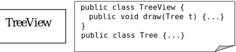
(13) Chapter 2.. A GENERIC COMPONENT MODEL. The basic idea in this paper is that a good design is well-structured, that is, it is decomposed in a way that exhibits good software engineering properties such as modularity, reusability, and understandability. More specifically, a good decomposition results in smaller parts each can be analyzed and understood easily with as little information from the others as possible; such decomposition also makes the design more reusable and evolvable, in part or in whole. Since the same decomposition principle holds across different levels of abstractions, our goal is to derive a generic model that captures the principle.. 2.1 Component and Interface A component is any tangible software artifact that provides knowledge or services through its interface. The types of components vary, and may include high-level documents such as system architectures, concrete implementations such as Java packages, classes, methods, or running systems such as Web servers. Components can be combined according to rules associated with their interfaces to form larger components. Consequently, the forms of interfaces and the ways components are combined depend on the types of the components. In case the target audience of a component (e.g. A UML diagram modeling one part of a system) is human; it is still possible to refer to the “interface” of such component (e.g. the “intended” visualization of the UML diagram to be rendered by supporting tools). Without loss of generality, it is helpful to consider that the interface of a component provides a language for its user to assess or interact with the component. To help illustration, we also present a simple graphical notation to represent components. Figure 1 shows diagrammatically a TreeView component as a rectangle box. The diagram indicates that TreeView provides two sets of vocabularies, TreeView and Tree, in its interface, where Tree. represents necessary vocabulary to complete TreeView, and itself can also be a standalone component provided that it is defined without the presence of TreeView. As with the other components used in the rest of the paper, the component is in fact associated with actual Java elements, mostly a set of related classes packaged together providing a designated service. For example, the TreeView component may correspond to a Java package that contains a TreeView and a Tree class.. 5.
(14) TreeView. public class TreeView { public void draw(Tree t) {...} } public class Tree {...}. Figure 1. A TreeView Component. 2.2 Domain, Context, and Polymorphism Holistically, a system consists of multiple components interconnected with each other. Atomistically, a component is placed within certain context so that it is fully defined. In case the component is an executable software entities, the component functions by interacting with its context, where the context can be any medium through which the component can obtain necessary help it requires. Because we refer polymorphism to the ability of a component to exhibit different behaviors under different contexts, we divide the context of a component conceptually into the intrinsic part and the polymorphic part. The former corresponds to the “hard-wired” components used by the component which is not replaceable without combing through the internals of the component. The latter, on the other hand, corresponds to those components that are replaceable by design, and there usually exist some language mechanisms to indicate the intension. Accordingly, the interface of a component is divided conceptually into the domain, which refers to the primary functionality of the component, and polymorphism interface (or polymorphism for short when no ambiguity arises), which indicates the part of the interface used for customization. We say a component is polymorphic if it provides some polymorphism interface. Because the domain of a component characterizes what the component does, we often use domain and component interchangeably. Consider a Java method as an example. We can refer its signature as its interface. The method is considered polymorphic if, for example, its control flow depends on an instance variable changeable other entities. It is also polymorphic if such control information is passed as a parameter. In this case part of the signature is considered the polymorphism of the method. As another example, a C++ template can be regarded as a component and the template parameters its polymorphism. Other polymorphism examples include the roles of the PATH environment variable or preference file to an application.. 6.
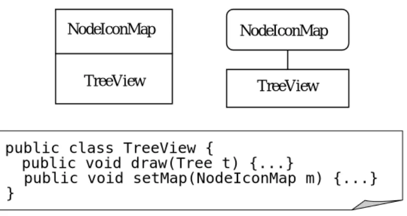
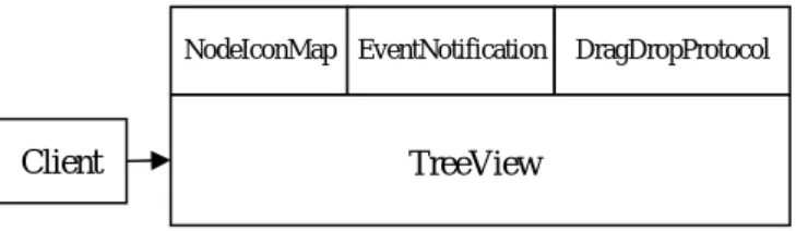
(15) Diagrammatically, using the same TreeView example described previously, we can introduce a polymorphism NodeIconMap that allows clients to customize the icons used to represent different kinds of tree nodes, as shown in Figure 2.. NodeIconMap. NodeIconMap. TreeView. TreeView. public class TreeView { public void draw(Tree t) {...} public void setMap(NodeIconMap m) {...} }. Figure 2. A Polymorphic TreeView. 2.3 Component Collaboration Component collaboration is also modeled as components interacting with their contexts. We use collaboration interface to indicate the part of the polymorphism interface that is used for such purpose. Component collaboration is also a general concept that shows up in very different forms. For example, collaboration can be achieved through coordinated use of instance variables among class methods, shared memory among multiple threads, or a shared database among distributed systems. In object-oriented systems, dedicated classes or frameworks can be created just for the purpose of collaboration. Consider the TreeView example again which is further augmented with two collaboration interfaces: EventNotification and DragDropProtocol. As shown in Figure 3, TreeView uses EventNotification as a notification service through which it can notify. other components whenever certain user operations, such as mouse clicks, have been applied to the tree nodes it displays. On the other hand, DragDropProtocol declares that the component is willing to participate in a desktop-wise drag-and-drop protocol. Notice that DragDropProtocol may belong to another usually more basic component (e.g. a. drag-and-drop subsystem), whereas EventNotification and NodeIconMap may belong to the TreeView domain.. 7.
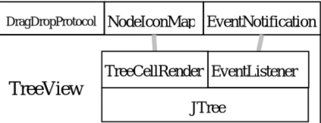
(16) NodeIconMap EventNotification. Client. DragDropProtocol. TreeView. Figure 3. Collaboration Interfaces The collaboration interface declared in the example above use object composition. We can also model inheritance as the collaboration between a base class and its descendents, and the collaboration scheme can be quite sophisticated (due to the expressive power provided by OO). Consider the Template Method (TM) pattern described in [1], as illustrated in Figure 4, where we regard AbstractClass as a component with PrimitiveOperations as its polymorphism. The base class where the channel of communication between the abstract class and the concrete class are in a way prescribed by the pattern: a set of abstract methods in AbstractClass waiting extension by its subclasses. In our notation, we can annotate the. polymorphism with “stereotypes” to clarify what the intended collaboration means. Similar to collective collaboration, collective inheritance between two components is also common. Figure 4 also illustrates the concept of object-oriented frameworks.. PrimitiveOperati. ExtensionPoints. AbstractClass. Framework. Figure 4. Collective collaboration among components. 2.4 Component Composition Component composition corresponds to the construction of a proper context linking the polymorphism interfaces of the components under assembly, so that not only each component receives proper context it requests, but also the resulting ensemble provides the service that matches the interface declared by the composite component. To simplify discussion, we refer composition to the part of artifacts that devote to such binding purpose. Composition can be as simple as a wrapper providing a simple layer of indirection, or can be complicated that it entitles a coalition of collaborating objects to. 8.
(17) complete the job. Figure 5 sketches the composition inside TreeView that consists of implementation logic that makes use of JTree and related interfaces such as TreeCellRenderer and EventListener from the Java Swing library.. DragDropProtocol. NodeIconMap EventNotification TreeCellRender EventListener. TreeView JTree. Figure 5. Composition inside TreeView. 2.5 Some Component-Oriented Design Guidelines The component model presented so far has already provided a concept framework where software designs can be evaluated. Below we present several basic design rules that are commonly used in our system design and implementation. Although these rules stem from fundamental software engineering principles, they are presented more from a component- and reuse-oriented perspective. Hence we coin the term design style to indicate that these rules reflect our “preferred” way of structuring a complex system and what a good design looks like. Different sets of rules are certainly possible with different design objectives under different situations. Structure software designs in terms of the component model. The rule implies that given an artifact in a (composite) component, it should be straightforward to identify its role, i.e. whether it is part of the domain, polymorphism, collaboration, or composition of the component. Each artifact should dedicate to one role. In particular, artifacts involved in composition should only concentrate on managerial tasks and create a smooth working environment for the components being composed; they do not involve in actual service providing in an essential way. Similarly, managed components should not be aware of and/or spend efforts on high-level managerial tasks. Such a worker-manager separation principle is in fact the foundation of our model. Components should be designed with maximal applicability and usability. A component is more applicable than the other (with roughly the same functionality) if it can be used, conceptually, under more contexts then the other. A component is more usable if the effort needed to fit the component into a design is less. Usability also reflects the effort needed for 9.
(18) one to understand the component in order to make proper use of it. For example, a Java interface is considered more applicable than a Java class that implements it, but less usable. We use reusability to summarize both driving forces that often contradict each other during design. Note that the reusability of a component also reflects the reusability of its parts. In other words, for two components with identical interfaces, the one with more reusable internals is considered more reusable. As a result, the tradeoffs between applicability and usability for each of the components in a larger design may become difficult to make. A component should concentrate on single domain of service that covers exactly what it offers; the component should know and use services from its context no more than what. it. needs. This rule is derived from the maximal reusability principle but from a more atomistic, component-oriented perspective. If the domain is incomplete for the problem a component intends to solve, the usability is hurt because it implies the missing part is substantial and not easy to fill in. If the domain supports multiple purposes, breaking it. up. into. many. single-purpose domains increases applicability. One intention of the self-containedness principle is to achieve separation of concerns – one can inspect the component with minimal efforts spent on tracing its correlations with other components. A quick example is to design subroutines with strong cohesion and good names indicating their purposes exactly [6]. The modular design principle governing module cohesion and coupling [5] is another example. Increase component reusability by focusing on core functionality and delegating irrelevant decisions to context. For a valuable component (e.g. which contains code that has undergone substantial engineering effort), we can consider maximizing its reusability by introducing a dedicated interface that is geared toward its own domain,. and declares the exact help it. needs through polymorphism. An immediate example is the JTree component from the Java Swing library. Instead of depending on a specific definition of tree representation (i.e. TreeNode) where the children addition and manipulation are somewhat irrelevant for displaying purpose, a dedicated interface TreeModel is created just enough for JTree to perform. This practice results in more applicable components, but incurs extra burden both from performance and usability perspective. In contrast to a compact design that is engineered for a specific problem, however, the principle may lead to extra wrapping layers, in exchange for overall reusability and adaptability.. 10.
(19) Favor simple collaboration. When decomposing a component into smaller ones, it is desirable that the design results in simple collaboration among components. Complicated collaboration not only hurt the usability of the involving components, but also. their. applicability due to the constraints imposed. This is the reason people prefer not to use (deep) inheritance when object composition – a simpler form of collaboration – suffices. The complexity of a collaboration relation is not determined just by which language mechanism is used, but rather by the efforts required to understand and use it. For example, collaboration via global variables is consider bad, if not worst, since the components need to be studied are potentially unlimited, and race conditions need to be analyzed. As a rule of thumb, we favor memoryless over stateful collaboration, where the latter implies that both parties need to maintain the state correctly. In addition, we favor. one-way. over. bidirectional collaboration. One-way collaboration implies that one component can carry out the request processing without requesting additional information from its requestor. Object composition without passing object references around. (e.g.. for. callbacks). is. considered one-way. As we regard inheritance a collaboration scheme between the base class and the subclass, deep inheritance may result in complicated collaboration that involves a chain of parent-child communication.. 11.
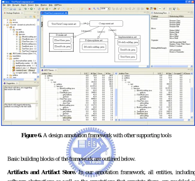
(20) Chapter 3. A DESIGN ANNOTATION AND EVALUATION FRAMEWORK Based on the generic component model, we have developed a corresponding annotation and evaluation framework for software design. The system does not limit the types of artifacts to Java abstractions, and can be used to document high-level architectures or implementation with varying degree of details.. 3.1 Framework Overview Figure 6 shows our Eclipse-based annotation framework that displays designs in terms of the component model. One objective of the framework is to provide a means for software developers to quickly grasp the overall architecture and organization of a software system, and to browse into different parts of the system without too much effort. This is achieved through the use of our canonical component-oriented design representation, where the role of each artifact in a design can be determined relatively easily. In practice, the framework helps developers in organizing Java classes and packages, by providing a readily useful tool rather than resorting to full-blown environment support. Furthermore, the annotation framework can also be used before actual artifacts are developed, providing skeletons and documents guiding the development process for a project. The annotation framework, and the generic component model underpinning it, is also the basis for more advanced CASE tools. For example, the annotation framework in Figure 9 also contains two important features. First, there is a refactoring module that provides refactoring suggestions based on user-defined criteria, although currently one needs to write code in order to add new criteria and corresponding refactoring methods into the system. The second feature is a metrics module that displays user-defined metrics based on the component model or any other information (hence programming efforts are also needed to add new metrics). The metrics module itself helps the user to quickly assess various parts of the system. In addition, it also works hand in hand with the refactoring module, by showing the changes in various metrics before and after a refactoring procedure is done. 12.
(21) Figure 6. A design annotation framework with other supporting tools. Basic building blocks of the framework are outlined below. z. Artifacts and Artifact Store. In our annotation framework, all entities, including software abstractions as well as the annotations that annotate them, are modeled as artifacts (Artifact) each assigned a unique URI that serves as its identifier. Artifacts are run-time objects managed by ArtifactStore, which is responsible of bridging the artifact world with the (concrete) file system. Specifically, each artifact corresponds to a file in a file system. ArtifactStore not only has to convert between files and artifacts upon request, but also serves as an event broker among artifacts so that an artifact is informed when its corresponding file is modified externally, and more importantly, when other artifacts that the artifact depends on change their states.. z. XML-based Annotation Syntax.. In order to be extensible so that new types of. components as well as inter-component relations can be defined, our framework includes a generic XML-based language for artifact definition and annotation. In particular, each artifact has an associated XML element that describes the types of the artifact and its relations with other artifacts. In short, these annotations form a. 13.
(22) user-defined ontology describing the system under examination. As such, new types of artifacts can be created and defined using XML; that is, they are maintained as XML documents in the file system directly. On the other hand, existing artifacts such as Java packages and programs, images, HTML files, etc. have their own persistence forms that our annotation framework does not and should not interfere with. It is the job of ArtifactStore to maintain the mapping between these artifacts to their XML-based. annotations. Note that the ontology built by the user through the artifact and annotation constructs forms the basis of our annotation framework. In fact, flexible text-based querying support can be provided for user to investigate the system under annotation more quickly. Other more user-friendly graphical interfaces are also conceivable to help user visualize many aspects of the system, some of which will be discussed shortly z. Generic Graph Modeling Language. To visualize the ontology as a network of inter-connected artifacts, we also developed a generic graph modeling language. The language plays an assisting role by attaching graphical rendering information to artifacts and their inter-relations. Although these graphical information are also maintained within the XML annotations, they do not interfering with the main content of the annotations. In other words, the graphical part inside an annotation can be removed without affecting the annotation, or the ontological aspect designated by the user.. z. Metrics and Refactoring Support. To further enhance the annotation and evaluation capabilities of the framework, we also developed an extensible metrics subsystem. The metrics subsystem allows users to add new metrics in terms of Java classes (Metric), where each metric replies a numerical measurement for any given artifact it recognizes and accepts. Furthermore, the user can configure what metrics to display with different scopes that are also customizable. In the following sections we will describe the language for artifact definition and. annotation. In the next chapter we will describe additional metrics and refactoring support that are developed on top of the basic framework.. 14.
(23) 3.2 An XML-Based Language for Artifact Definition and Annotation We adopt XML as the sole format for annotation representation due to its wide-spread use and the availability of robust processing tools. The design of the language itself is also affected by the syntactical features of XML. Firstly, instead of viewing all structurally valid XML documents as acceptable annotations, we consider only a subset of XML documents that can be mapped to run-time counterparts bi-directionally in a straightforward manner. These run-time counterparts are easier to manipulate programmatically with less processing overhead. Secondly, “reserved” language keywords are distinguished from others within an XML document via a particular namespace. Specifically, in the examples below XML elements and attribute names with namespace “m” (i.e. with “m:” prefix) are consider reserved with language-level semantics. In addition, these reserved constructs impose syntactical constraints upon the rest of the contents within the XML document or even other XML documents.. This is in contrast with other syntax specification mechanisms, notably. XML Schema, where syntax declarations and applications are separated. Consider the case in which the developer employs the commonly used Abstract Factory design pattern [1] in part of his/her overall system design. A possible annotation is listed below, where we omit namespace declarations for simplicity:. <myAF m:uri=”/myDesign/myAF”> <desc>An application of Abstract Factory</desc> <abstractFactory m:uri=”/mySystem/src/ShapeFactory.java”/> <abstractProduct m:uri=”/mySystem/src/Rectangle.java”/> <abstractProduct m:uri=”/mySystem/src/Oval.java”/> <concreteFactory m:uri=”/mySystem/src/MyShapeFactory.java”/> <concreteProduct m:uri=”/mySystem/src/RectangleImpl.java”/> <concreteProduct m:uri=”/mySystem/src/OvalImpl.java”/> </myAF>. The intention of the annotation is to state that, six of the Java classes in the overall system design are created following the Abstract Factory pattern. Specifically, the pattern suggests that when an application needs to create and manipulate a family of objects, such 15.
(24) as graphical shapes illustrated in the example above, instead of using concrete objects directly (e.g. RectangleImpl and OvalImpl), it is beneficial to create and manipulate them via a separate set of interfaces (ShapeFactory, Rectangle and Oval). The latter design not only makes the access interface to the family of objects explicit and shield the developer from unnecessary implementation details (i.e. the information hiding principle), but also permits the introduction of another set of concrete objects (e.g. for different operating systems) with minimal impact. As mentioned before, the XML attributes in the annotation above with namespace m are interpreted as meta-level constructs. First, the annotation itself is assigned with the URI “/myDesign/myAF”, followed with the annotated Java programs each also with a specific URI. Although such a “free-form” style of annotations can be useful in many cases, for example, for other developers who are familiar with design patterns to understand what the annotation means, to further enhance the clarity and precision, as well as to permit automated analyses, our framework includes a syntactical validating mechanism so that the developer can control the structure and contents that go into a particular type of annotations. Using the example above, the developer may create an Abstract Factory “template”, as shown below, to explicitly state the intention and required syntax:. <AbstractFactory m:uri=”/pattern/AbstractFactory”> <desc>The Abstract Factory pattern</desc> <m:rel. tag=”abstractFactory” m:uri=”/java/AbstractClass”/>. <m:rels tag=”abstractProduct” m:uri=”/java/Interface”/> <m:rel. tag=”concreteFactory” m:uri=”/java/Class”/>. <m:rels tag=”concreteProduct” m:uri=”/java/Class”/> </AbstractFactory>. The annotation above, which itself is also an artifact with a URI, states that any conforming annotation should contain for types of child elements with tags “abstractFactory,”. “abstractProduct,”. “concreteFactory,”. and. “concreteProduct,” respectively; each child element also contains a URI attribute linking to an artifact of a specific “type” (defined below). The meta construct “m:rel” states that the child element should occur only once, while the “m:rels” permits multiple occurrences. 16.
(25) Note that some artifacts such as “/java/AbstractClass” and “/java/Interface” are artifacts defined elsewhere. With the template at hand the original Abstract Factory annotation is modified accordingly:. <myAF m:uri=”/myDesign/myAF”> <m:is m:uri=”/pattern/AbstractFactory”/> <abstractFactory m:uri=”/mySystem/src/ShapeFactory.java”/> <abstractProduct m:uri=”/mySystem/src/Rectangle.java”/> <abstractProduct m:uri=”/mySystem/src/Oval.java”/> <concreteFactory m:uri=”/mySystem/src/MyShapeFactory.java”/> <concreteProduct m:uri=”/mySystem/src/RectangleImpl.java”/> <concreteProduct m:uri=”/mySystem/src/OvalImpl.java”/> </myAF>. In particular, the “m:is” element above states that the annotation should satisfy the syntactical constraints indicated in the artifact “/pattern/AbstractFactory.” The annotation framework can then perform syntax checking solely based on the annotations. Note that the example above is somewhat simple-minded, because in the actual Abstract Factory pattern there is usually more than one suite of concrete products to justify the use of the pattern, but in this example they can not be easily distinguished. To remain general, at least in current stage of development, the annotation framework is purely syntax-based; that is, it checks whether an annotation has correct syntax but does not verify whether the annotated artifacts have correct semantics, respectively. Nevertheless, we believe the syntax-based annotation framework can already provide useful mechanisms for documentation and evaluation purposes.. 3.3 A Generic Graph Modeling Language Because the annotation framework allows the user to define new artifacts denoting arbitrary, high-level concepts, and link them with existing artifacts flexibly using. 17.
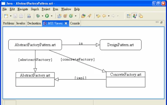
(26) annotations which are also user defined, the framework can be regarded as an ontology definition and manipulation framework. The ontology created by the user can serve as the basis for more advanced and user-friendly CASE tools. First of all, it is desirable to be able to visualize the potentially complex artifact relations graphically. For this purpose, we design and implement a general-purpose graph modeling language (GML). The objective of the language is to provide a flexible mean for users to attach arbitrary information to different artifacts. The example below illustrates the syntax of GML using the same Abstract Factory pattern example above: <gml:graph> <gml:node key="node2"> <shape label="DesignPattern.art" type="block" h="40" w="165" y="46" x="383"/> <artifact m:uri="vos://vos.test/pattern/af/DesignPattern.art"/> </gml:node> <gml:node key="node3"> <shape label="ConcreteFactory.art" type="container" h="59" w="155" y="166" x="408"/> <artifact m:uri="vos://vos.test/pattern/af/ConcreteFactory.art"/> </gml:node> <gml:node key="node1"> <shape label="AbstractFactoryPattern.art" type="block" h="40" w="212" y="46" x="21"/> <artifact m:uri="vos://vos.test/pattern/af/AbstractFactoryPattern.art"/> </gml:node> <gml:node key="node4"> <shape label="AbstractFactory.art" type="container" h="53" w="154" y="169" x="50"/> <artifact m:uri="vos://vos.test/pattern/af/AbstractFactory.art"/> </gml:node> <gml:link dest="node2" src="node1" tag="is"> <link type="HollowArr" label="is"/> </gml:link> <gml:link dest="node3" src="node1" tag="concreteFactory"> <link type="HollowArr" label="[concreteFactory]"/> </gml:link> <gml:link dest="node4" src="node1" tag="abstractFactory"> <link type="HollowArr" label="[abstractFactory]"/>. 18.
(27) </gml:link> <gml:link dest="node4" src="node3" tag="impl"> <link type="HollowArr" label="[impl]"/> </gml:link> </gml:graph>. Similar to the design of the annotation syntax, GML also designates a set of reserved keywords, i.e. “gml:graph,” “gml:node,” and “gml:link,” that together encode arbitrary graphs. Child elements under these elements are considered annotations created by the user. In particular, the “shape” element under each “gml:node” element as well as the “link” annotation under each “gml:link” element contain information specifically for graphical display. Figure 7 below shows the graphical representation of the GML example just mentioned:. Figure 7. The graph modeling framework. 19.
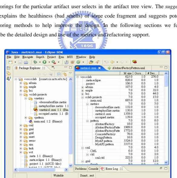
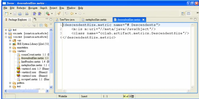
(28) Chapter 4.. METRICS SUBSYSTEM AND REFACTORING. SUPPORT Another important objective of our annotation framework is to facilitate automated design comprehension and evaluation. Although meetings and inspections help assess the status of project, they rely on the perception of the participants and their willingness to communicate what they know. It helps to be able to manage the evolution of a product with objective measures [11]. We have developed an extensible metrics subsystem for measuring the progress and healthiness of a project objectively and continuously. Figure 8 shows the metrics tool supported by our framework, in which the metric “# Descendents” exploits the parent-child artifact relations to calculate the size of descendents for all artifacts inside a Java project. Figure 9 shows the refactoring tool supported by our framework, in which there are two views: suggestion view and refactoring view. The refactoring view lists the useful refactorings for the particular artifact user selects in the artifact tree view. The suggestion view explains the healthiness (bad smells) of some code fragment and suggests potential refactoring methods to help improve the design. In the following sections we further describe the detailed design and use of the metrics and refactoring support.. Figure 8. Metrics subsystem overview. 20.
(29) Figure 9. Refactoring subsystem Overview. 4.1 Introduction to Metrics The capability of software metrics plays an important role in improving the quality of the software process. A metric is a quantitative indicator of an attribute. Many software metrics have been proposed, such as Number of Lines of Code, Number of Branching Points [19], Number of Variables and Operators [20], and Number of Functional Requirements [21]. A properly designed set of metrics helps developers see what may actually be right and wrong when design changes. For example, a metric may measure the number of requirements implemented correctly in the design. If this measure is not always monitored, requirements drift may occur and the product may be delivered without meeting the client’s needs. Many approaches to metrics are based on [12], which contains six object-oriented metrics criteria (Weighted Methods per Class, Depth of Inheritance Tree, Number of Children, Coupling between Object Classes, Response for a Class, Lack of Cohesion in Methods) that are theoretically-grounded and empirically validated. [13] presents the results of the experimentally investigated suite of object-oriented design metrics introduced in [12]. Of course, there are also other kinds of metrics proposed. For example, [14] proposes the. 21.
(30) code complexity metrics (Average Method Complexity) and design complexity metrics (Class Design Entropy) to enhance the WMC metrics introduced in [12]. [15] focuses on reusability and reviews six types of models and metrics. It provides a classification structure that can help users select suitable metrics to achieve an objective reusability goal. [16] compares two different approaches to measure system cohesion, and relies on user intuition to decide the better approach. Automated metrics tools help developers assess the quality of internal structure of a complex system rapidly. [17] lists many types of metrics tools as well as commercial tools. There are also many open-source software for software metrics [18]. Currently, there are a number of integrated development environments (IDE) (Eclipse, NetBeans, Vistual Studio .NET, Refactoring Browser, etc.) that allow developers to add metrics plug-ins. In some cases, the programmer can customize the warning thresholds, messages, and corrections for particular metrics, respectively. Most of these tools calculate metrics based on object relationship and their dependency. In the following sections we show some modifications are needed to adapt these metrics for our generic component model.. 4.2 The Metrics Subsystem Our metrics subsystem supports some important metrics such as lines of code, size, and the inheritance relationships among classes (and components). Other common metrics such as the number of methods/statements/comments, the lines of code for each class method, the depth of inheritance, the coupling between components, and so on, are also provided. A metric (modeled as an IMetric class) in our system is an object that can calculate and return a numerical value for any artifact it recognized. The metrics subsystem allows users to add new metrics, and to configure what metrics to display as well as customize their scopes, respectively. Below we use an example to illustrate how to augment the metrics subsystem with new metrics. First of all, the standard interface a metric needs to implement is shown below: public interface IMetric { public String getName(); public String getType();. 22.
(31) public float getMeasure(); public float computeMeasure(IArtifact art); }. Consider a metric that calculates the number of all descendents for any given artifact. As show below, the DescendentSize class implements the calculation in its computeSize() method: public class DescendentSize extends Metric { . . . public float computeMeasure(IArtifact art) { return computeSize(art); } public int computeSize(IArtifact art) { IArtifact[] as = art.getChildren(); int count = 1; for (int i=0; i<as.length; i++) { count += computeSize (as[i]); } } }. With the implementation at hand, we can augment the metrics system with a new artifact (also an annotation) representing the metric, as illustrated in Figure 10 below. <descendentSize.metric name="# Descendents"> <m:is m:uri="//meta/java/JavaObject"/> <class name="cclab.artifact.metrics.DescendentSize"/> </descendentSize.metric>. 23.
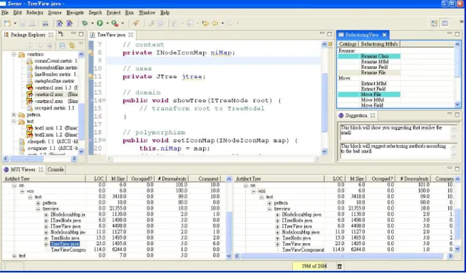
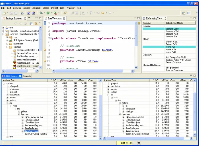
(32) Figure 10. User-defined metric DescendentSize The metrics subsystem can be configured to include the newly defined metric by interpreting the annotation and creating the metric object with the class name via Java reflection mechanisms.. 4.3 Metrics-driven Refactoring Support In [22] Fowler proposes a list of clues or symptoms that suggest refactoring opportunities. These symptoms are named “bad smells” and their detection should be achieved from “the programmer intuition and experience”. As the benefits of refactoring become widely recognized, research efforts in systematic tool support for refactoring also accumulate, many of which address refactoring from the metrics perspective. In [23], change metrics are used among different versions of a system and hint which refactoring methods have been applied at each evolution step. [25] Lorenz defines the thresholds and criteria for various metrics for object-oriented languages, to determine potential bad smells. Our framework also provides some refactoring support. As shown in Figure 11, several metrics are displayed representing various aspect of current design. Bad smells are modeled as metrics based on which detection criteria are also defined. In other words, each artifact may be associated with several bad smells when it matches the criteria of these bad smells [22]. As also shown in Figure 11, when the user selects a particular artifact, its bad smells, if any, are highlighted and potential refactoring methods are suggested. Furthermore, if the. 24.
(33) user applies a specific refactoring method, the system shows both the overall metrics before and after the change, therefore providing a powerful tool for design assessment and evolution. Figure 12 shows further explanations and possible refactoring candidates to resolve a given bad smell.. Figure 11. Artifact tree view and refactoring view relation. 25.
(34) Figure 12. Artifact tree view and suggestion view relation. 4.4 Future Work for the Metrics Subsystem The metrics subsystem has many potential uses. Important categories under development are summarized below: z. Ontology Housekeeping. This category of metrics highlights inconsistencies among artifact annotations, including missing links or mismatched types. They are particularly useful when the system undergoes some design change.. z. Design Rule Checking. This aspect is related to the stylized design organization and representation introduced in Chapter 2 and 3. As an example, one can define a metric that inspect Java programs to see if they violate the dependency requirements among packages within a source tree, where the dependency requirements are defined via the annotation framework.. 26.
(35) z. Metrics-based Design Querying. The ontology (incrementally) built by the developer can already permit flexible query mechanisms so that the developer can form complex queries about the ontology to gain insight of the many aspects of the system. With metrics introduced, the query capability can be enhanced enormously.. 27.
(36) Chapter 5.. DISCUSSIONS AND RELATED WORK. The subject addressed in this thesis relates our work to a wide variety of research areas in software engineering and programming languages. For example, the concepts of context or polymorphism have been the foundation of programming language research since the beginning. Here we concentrate on software complexity handling, or more specifically the control of the coupling and cohesion of software modules. Complexity handling has been the central theme addressed by fundamental software engineering principles documented over the years. [1] has organized and explained many principles systematically. Our work differs from this more traditional approach in that instead of basing discussions on general concepts of software modules or concrete code fragments and their dependencies, we develop an abstract model trying to capture principles in a more structural and semantic manner. Also, we try to minimize scope for our evaluation criteria and focus on the notion of maximal reusability. While we believe this approach to complexity handling gives software developers a simpler roadmap guiding their design activities, it does not replace the need to understand those well-established software engineering principles. Existing component models and technologies often stress on mechanisms and abstractions for component specification and assembly. In contrast, we attempt to captures the essence of component and its reuse orientation across different levels of abstractions. We are more interested in how to apply the component principles using any OO languages, and believe that discipline around interface and black-box reuse is not sufficient, just like encapsulation and inheritance principles and mechanisms supported by OO – they are necessary but too primitive. Our approach focuses more on static structure of software designs, and provides a natural organization scheme. There are also extensive research efforts directly targeted at the complexity and implications of various kinds of component correlation. For example, [8] discusses the problem of extraneous embedded knowledge – a component knowing information not conceptually required for what it does – and proposed the use of implicit context to hide these information while communicating with the component. In [9] language constructs are proposed for specifying collaboration interfaces that support bidirectional communication among components. A component can declare both its provided and expected services in its interface, much like the domain and polymorphism in our model, except the emphasis is. 28.
(37) placed more on complex forms of collaboration. With support at the language level, the binding mechanism between two components can be simplified, as opposed to using excessive wrappers that is also pointed out here. In [10], various forms of (primitive) object-oriented composition are analyzed and classified (e.g. overriding, transparent redirection, acquisition, subtyping, and polymorphism). The paper proposes language support for expressing linguistically these different types of composition, which coincides with our objective despite the difference in. Complexity handling is also the main subject studied by the reengineering and reverse engineering communities, which also come with a wealth of research results. Many approaches provide visualization tools for software developers to analyze the dependency and other program structures. For example, a recent approach [7] proposes a way of visualizing the internal structure of classes, called class blueprint, and provides guidelines and hints for spotting bad designs. Although the objective is similar - to help developers in evaluating and therefore improving designs, we argue that similar approaches in this direction often gross over important information embedded in various artifacts, such as the roles they play in the design. Although this may be what we can expect given the raw materials reverse engineering tools can work on, we believe our work can pave the way toward more semantics-unveiling techniques in this area. One of the current trends in refactoring is when and where refactoring should be done. The starting point of this, as mentioned before, is the Flower’s classical book on refactoring [22]. There are 22 bad smells listed in an informal manner, with a simple description and a set of suggested refactorings to improve the code. Tool support is necessary to assist the human intuition in a very efficient and effective way. The tool presented in [27] provides a generic approach (distance based cohesion) to generate visualizations supporting the developer to identify candidates for refactorings. To produce the distance matrix, the user creates a repository for the whole project, then extract the relevant symbols likes classes, methods etc. into the tool which is implemented as a relational database. The user has to select the classes to be analyzed. After the distances are calculated and distances have re-arranged, the tool can calculate positions and other information from the repository and display them with a VRML-client. TTCN-3 [28] is an Eclipse-based development environment developed by Motorola that provides suitable metrics and refactorings to enable the assessment and automatic restructuring of test suites. TTCN-3 uses Eclipse’s refactoring wizard that displays a preview of all resulting changes and uses its Java 29.
(38) Development Tools (JDT) to parse Java source code into AST trees for metrics calculation. This system is in many ways similar to ours. However, it does not support bad smells directly and reasonably intuitively, nor does it provide further explanations about the refactoring methods it suggests or where the bad smells occur. Our tool lists bad smells sorted according to some priority (based on their corresponding metrics after proper normalization), so that more “urgent” design flaws are shown before the rest.. 30.
(39) Chapter 6.. CONCLUSIONS AND FUTURE WORK. We have developed an abstract component model that is capable of representing software artifacts of various types at different abstraction levels in a uniform way. We believe that the basic concepts introduced in the model - context, domain, polymorphism, collaboration, and management - provide a useful vocabulary in describing software designs. In terms of the model, we have also presented the maximal reusability principle as a tradeoff between component applicability and usability. By using the principle and other principles derived from it, we were able to analyze several fundamental principles as well as some modern techniques such as design patterns and aspect-oriented programming easily. In particular, we showed how to derive several design patterns naturally from reusability point of view, based on which a simple classification scheme for design patterns was also given. We have argued that an understanding of the connection between design patterns and underlying software engineering principles helps in explaining design patterns. To aid in presenting the connection, we have developed a simple component model that is capable of describing both fundamental principles and design patterns at a reasonably abstract level. Using the model, we have tried to clarify the driving forces behind design patterns and show how to identify, combine, and adjust various patterns based on situation-specific considerations. Another contribution of this paper is in pointing out that using polymorphism and context as `first-class design elements' can tie together concepts ranging from basic programming language constructs to high-level design abstractions. In fact, it is this sort of generalization of polymorphism that enables the uniform treatment of collaboration and management in our model. We believe this approach can help in improving insight into software development in general. One question this paper may bring up is: if fundamental principles are seemingly enough, why does the Design Pattern movement receive so much attention in the first place? To be very clear, we are not trying to replace design patterns with principles. As general and universal as principles can be, they are by no mean trivial to apply, especially when software systems become larger. Although there may not be a commonly agreed upon theory about the source of design patterns, it is safe to say that many design patterns try to document successful applications of principles under different circumstances. On the other hand, patterns still have not seemed to solve problems similar to those that principles deal with, namely, how to cope with large-scale system design using design patterns. We believe our work can provide a good starting point in this regard. 31.
(40) While this thesis may appear trivial to some readers, most can agree the indispensable efforts they had to spend on figuring out those continuously emerging technologies (and their acronyms), and more importantly their relations with each others and previous work. The framework is our attempt to provide an immediately useful tool not only to help software developers in performing design “refactoring” quickly and more objectively, but also to help them in sieving through literatures more efficiently and applying them more soundly. In other words, the framework complements and reconciles existing approaches and techniques. The framework represents the core of our ongoing research toward a streamlined CASE tool that can manage requirements, designs, and implementation in a systematic way. The near-term goal is to have a semi-automatic system that can assist programmers to annotate and manage Java programs according to the component model. With annotations, one can browse high-level architectures through low-level code fragments in a uniform way, thus promoting traceability. Effective refactoring browser for designs can be developed accordingly. A more challenging problem afterwards is to establish a sound metric based on the principles as described before so as to enable a comprehensive and automatic design rule checking framework for the software design process.. 32.
(41) Chapter 7.. REFERENCES. [1] E. Gamma, R. Helm, R. Johnson, and J. Vlissides, “Design Patterns: Elements of Reusable Object-Oriented Software,” Addison-Wesley, 1995. [2] G. Kiczales, J. Lamping, A. Mendhekar, C. Maeda, C. V. Lopes, J.-M. Loingtier, and J. Irwin, “Aspect- oriented programming,” ECOOP'97 - Object-Oriented Programming 11th European Conference, 1997, pp. 220-242. [3] C. Szyperski, “Component Software: Beyond Object-Oriented Programming,” Addison-Wesley, 1998 [4] A. W. Brown, K.C. Wallnau, “The current state of cbse. IEEE Software”, Sept.-Oct. 1998, 15(5):37-46. [5] B. Meyer, “Object-Oriented Software Construction,” Prentice-Hall International, 1988. [6] S. McConnell, “Code Complete: A Practical Handbook of Software Construction,” Microsoft express, 1993. [7] M. Lanza and S. Ducasse. “A Categorization of Classes based on the Visualization of their Internal Structure: the Class Blueprint,” Proceedings of OOPSLA 01, pp. 300-311. [8] R.J. Walker and G.C. Murphy. “Implicit Context; Easing Software Evolution and Reuse,” SIGSOFT 2000 (FSE 8), pp. 69-78. [9] M. Mezini and K. Ostermann. “Integrating Independent Components with On-Demand Remodularization,” Proceedings of OOPSLA’02. Nov, 2002, pp. 52-67. [10] K. Ostermann and M. Mezini. “Object-Oriented Composition Untangled,” Proceedings of OOPSLA 01, pp. 283-299. [11] Softwaredioxide website, “http://www.softwaredioxide.com/Channels/FaqView.asp?id=164”. 33.
(42) [12] S. R. Chidamber and C. F. Kemerer. “A metrics suite for object oriented design. IEEE Transactions on Software Engineering,” 20(6), 1994, pp. 476-493. [13] Basili, V. R., Briand, L. C., and Melo, W. L., “A validation of object-oriented design metrics as quality indicators,” IEEE Transactions on Software Engineering, 22(10), 1996 pp. 751-761. [14] L. Etzkorn, J. Bansiya, and C. Davis, “Design and code complexity metrics for object-oriented classes,” Journal of Object Oriented Programming, 1999. [15] W. Frakes, C. Terry, “Software Reuse: Metrics and Models. ACM Computing Surveys,” Vol. 28, No. 2, June 1996, pp. 415-435. [16] L. Ott, B.K. Kang, B. Mehra, “Developing Measures of Class Cohesion for Object-Oriented Software,” 7th Annual Oregon Workshop on Software Metrics, June 1995. [17] A. E. Giles and G. T. Daich, ”Metrics Tools,” http://www.stsc.hill.af.mil/,” crosstalk Software Technology Support Center, Feb. 1995. [18] sourceFORGE.net website, http://sourceforge.net/ [19] T. McCabe, “A software complexity measure,” IEEE Transactions on Software Engineering, 2(6), Dec. 1976, pp. 308-320. [20] M. H. Halstead, “Elements of Software Science,” Elsevier, New York, 1977. [21] A. J. Albrecht & J. E. Gaffney, Jr., “Software function, source lines of code, and development effort prediction: A software science validation,” IEEE Transactions on Software Engineering, Vol. SE-9, 1983, pp. 639-648. [22] Martin Fowler, “Refactoring. Improving the Design of Existing Code,” Addison Wesley, 2000.. 34.
(43) [23] S. Demeyer, S. Ducasse, and O. Nierstrasz, ”Finding refactorings via change metrics,” In OOPSLA’ 2000, ACM Press 2000, pp. 166-177.. [24] S. Demeyer and S. Ducasse, “Metrics, Do They Really Help? ” Proceedings LMO'99, 1999, pp. 69-82. [25] M. Lorenz and J. Kidd. Object-oriented software metrics: a practical guide, Prentice-Hall, Inc., Upper Saddle River, NJ, USA, 1994. [26] Y. Crespo, C. Lopez, E. Manso, and R Marticorena, “Language Independent Metric Support towards Refactoring Inference,” 9th ECOOP’05, pp. 18-29. [27] F. Simon, F. Steinbruckner, C. Lewerentz, “Metrics Based Refactoring,” CSMR 2001, pp. 30-38. [28] P. Baker al. Etc, “TRex – The Refactoring and Metrics Tool for TTCN-3 Test Specifications,” TAIC PART 2006 workshop, 2006.. 35.
(44)
數據
+7
相關文件
Overview of a variety of business software, graphics and multimedia software, and home/personal/educational software Web applications and application software for
• If we use the authentic biography to show grammar in context, which language features / patterns might we guide students to notice and help them infer rules or hypothesis.. •
“More Joel on Software : Further Thoughts on Diverse and Occasionally Related Matters That Will Prove of Interest to Software Developers, Designers, and Managers, and to Those
“More Joel on Software : Further Thoughts on Diverse and Occasionally Related Matters That Will Prove of Interest to Software Developers, Designers, and Managers, and to Those
• Facilitating Field Studies in Hong Kong.. • PBL – A New Mode of
• In the present work, we confine our discussions to mass spectro metry-based proteomics, and to study design and data resources, tools and analysis in a research
and/or make predictions about the future behaviour of a system in the real world. ● requires the modeller to be creative and make choices, assumptions,
We will design a simple and effective iterative algorithm to implement “The parallel Tower of Hanoi problem”, and prove its moving is an optimal
