202 IEEE MICROWAVE AND GUIDED WAVE LETTERS, VOL. 8, NO. 5, MAY 1998
Design of a Beam-Switching Active
Microstrip Antenna Array
Young-Huang Chou and Shyh-Jong Chung
Abstract—An active microstrip antenna array with dual switch-ing beams were developed and demonstrated. The array con-tained several active antennas and an extra amplifier-embedded coupling (microstrip) line. Two injection-locking signals were used in the design, that is, the free-space mutual coupling between antennas and the injection signal on the coupling line tapped from the first oscillator in the array. By turning on and off the amplifier on the line, these two signals dominated in turn, producing two radiation modes with different main beams. A three-element H-plane array and a two-elementE-plane array were designed and measured. Both of the arrays had an out-of-phase radiation mode when the amplifier was turned off, and had an in-phase mode when the amplifier was on. Also, clean frequency spectra and good radiation patterns were measured, which demonstrated the validity of the present design.
Index Terms—Active antenna array, beam switching, injection lock.
I. INTRODUCTION
T
HE spatially power-combining technique for designing high-power and low-cost integrated antenna arrays has received much attention in the recent years [1], [2]. As can be found in the literature, two approaches, i.e., those with the internal and external injection-locking mechanisms, were used for the power combining. In the first approach, the mutual couplings between array elements, through free space or an embedded coupling network, provided the injection-locking signals. The phase delay between the adjacent antennas was locked so that the array could radiate the field in an in-phase mode (0 phase delay between adjacent elements) or an out-of-phase mode (180 phase delay), depending on the inter-element distance [3], [4]. In the second approach, the injection-locking signal came from an external oscillator and was distributed to all the active antennas in the array [5]. The phase delay between adjacent antennas was determined by the path lengths of the injection signal so that the field could be radiated to a predesigned direction.In this letter, a new spatially power combining active antenna array, which possesses two switching radiation modes, is proposed and demonstrated. The array contains several
suit-Manuscript received January 2, 1998. This work was supported by the National Science Council of the Republic of China under Grant 86-2215-E-009-033.
The authors are with the Department of Communication Engineering, National Chiao Tung University, Hsinchu 30039, Taiwan, R.O.C. (e-mail: [email protected]).
Publisher Item Identifier S 1051-8207(98)03456-4.
(a)
(b)
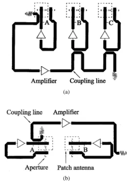
Fig. 1. (a) Three-element H-plane active antenna array. (b) Two-element
E-plane active antenna array.
ably spaced active antennas and an extra amplifier-embedded coupling (microstrip) line, as shown in Fig. 1. Two injection-locking mechanisms appear in the present design. The first injection signal comes from the free-space mutual couplings between antennas, which determines one of the array radiation modes. The other mode is due to the second injection-locking signal, which is directly tapped from the first oscillator in the array and is coupled to the rest ones through the extra coupling line. The tapped signal is enlarged by the amplifier to ensure the surpass of this signal over the mutual coupling one so that a stable radiation mode can be obtained. The electrical length of the coupling line between adjacent antennas decides the radiation direction of this mode. By turning off and on the amplifier, the first and the second injection-locking mechanisms dominate in turn, so that the two radiation modes are switched.
II. DESIGN
A three-element -plane array [Fig. 1(a)] and a two-element -plane array [Fig. 1(b)] were designed and mea-sured. The aperture-coupled feedback oscillator [6], with an
IEEE MICROWAVE AND GUIDED WAVE LETTERS, VOL. 8, NO. 5, MAY 1998 203 antenna substrate of and mil (thickness) and
a circuit substrate of and mil, was adopted to implement the arrays. A two-port aperture-coupled microstrip antenna with a transmission loss of 8 dB (due to the radiation of the patch) was located at the path of the oscillator feedback loop. An amplifier (designed using the NEC 32 484A HEMT) with about 10-dB small-signal gain was also placed in the loop to reach the gain requirement for oscillation. In addition, to satisfy the oscillation phase requirement, the electrical length of the feedback loop was adjusted to be a multiple of 360 . The finished active antenna oscillated at the frequency of 9.85 GHz.
The antennas in the -plane array oriented in the same direction and, for simplicity, those in the -plane array oriented in the opposite directions. The interelement spacing ( ) was chosen as for the -plane array and as for the -plane array, with being the free-space wavelength at 9.85 GHz. The corresponding mutual couplings between adjacent antennas were measured to be 19 and 23 dB, respectively. When the amplifier on the extra coupling line is turned off, the array oscillators are locked by these mutual injection signals. From [3], the locked array radiation mode is out-of-phase for a spacing ( -plane) and is in-phase for a spacing ( -plane), provided the free-running frequencies of all the oscillators are the same. But, due to the opposite orientations of the antennas, the actual radiation mode of the -plane array is changed to an out-of-phase mode.
When the amplifier on the extra coupling line is turned on, the other injection-locking mechanism happens. The amplifier is with the same design as those used in the feedback oscilla-tors and also has a gain of 10 dB. Part of the oscillating power of the first oscillator is drawn out by a 15-dB directional coupler to the coupling line and enlarged by the amplifier. The amplified signal is then injected to the rest oscillators through the 15-dB couplers. As shown in Fig. 1, the overall transmission path of this injection signal from point A of the first oscillator to the same reference point (B or C) of another oscillator consists of two couplers and two amplifiers (including the amplifier in the oscillator). The injection signal to points B or C is thus 10 dB ( dB) lower than the power at point A, which is large enough to overwhelm the free-space mutual coupling. (Note that this injection signal is 9 dB larger than the mutual coupling in the -plane array and 13 dB in the -plane array.) The radiation direction ( ) of the locked mode is determined by the phase delay ( ) from points A to B or B to C through the following relationship (neglecting the effect of the nonuniform radiation pattern of a single microstrip antenna):
(1)
where when the antennas are with the same orientation and when with opposite orientations. In the present study, was designed to be for the -plane array and 180 for the -plane array, so that both of the arrays have a broadside (in-phase) radiation when the amplifier is turned on.
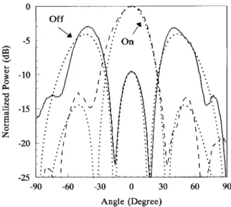
Fig. 2. Radiation patterns of the H-plane array when the amplifier is switched off and on. The dotted lines (1 1 1) represent the calculated results.
III. MEASUREMENT
Before measuring the switching effect, the free-running frequencies of the oscillators in each array were tuned the same by slightly adjusting the gate voltage of each oscillator. For the -plane array [Fig. 1(a)], the frequency was tuned at 9.765 GHz, and, for the -plane array [Fig. 1(b)], the frequency was at 9.923 GHz.
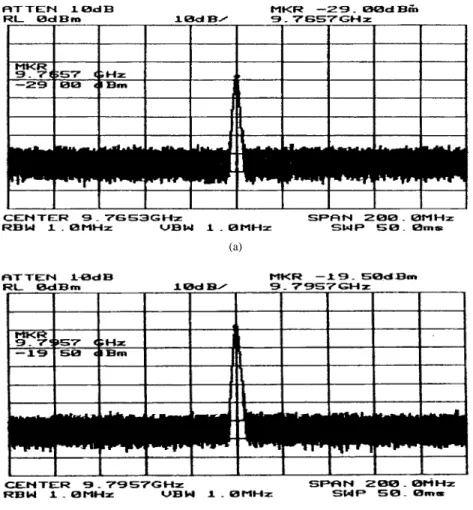
Fig. 2 shows the measured and calculated patterns of the two switching modes of the -plane array. (The calculated patterns were obtained by letting the input sources of the passive antennas with equal amplitudes and appropriate interelement phase delays.) It is seen that the measured and calculated patterns agree quite well with each other. When the amplifier on the coupling line was turned off, the phase delay between adjacent antennas should be locked at 180 . The measured pattern shows two symmetric main beams at , which are close to those of the calculated pattern at . When the amplifier was turned on, both of the patterns have a main beam at and two sidelobes at 50 . Also, it is noted that at (the main beam of the in-phase mode) and (maim beams of the out-of-phase mode), the measured level differences between the two (on and off) modes are about 10 dB, which are the same as the calculated ones. Fig. 3(a) and (b) presents the measured frequency spectra of the out-of-phase (off) mode and the in-phase (on) mode, respectively. The oscillating frequency of the out-of-phase mode is 9.766 GHz and that of the in-phase mode is 9.796 GHz. It is seen that both of the two modes have a clean spectrum, which means that all the oscillators in the array had been locked under the two injection-locking mechanisms. The measured and calculated patterns of the -plane array are illustrated in Fig. 4. When the amplifier on the coupling line was turned off, the radiation pattern was an out-of-phase mode, and as the amplifier was on, the pattern changed to an in-phase mode. A sharp deep of as large as 21.5 dB at of the measured out-of-phase pattern was obtained. Although not shown here, two clean frequency spectra, like
204 IEEE MICROWAVE AND GUIDED WAVE LETTERS, VOL. 8, NO. 5, MAY 1998
(a)
(b)
Fig. 3. Frequency spectra of the H-plane array with the amplifier on the coupling line (a) off and (b) on.
Fig. 4. Radiation patterns of the E-plane array when the amplifier is switched off and on. The dotted lines (1 1 1) represent the calculated results.
those presented in Fig. 3, were also measured for the two modes. The locked frequency of the out-of-phase mode is 9.925 GHz and that of the in-phase mode is 9.95 GHz.
REFERENCES
[1] J. A. Navarro and K. Chang, Integrated Active Antennas and Spatial
Power Combining. New York: Wiley, 1996.
[2] J. Lin and T. Itoh, “Active integrated antennas,” IEEE Trans. Microwave
Theory Tech., vol. 42, pp. 2186–2194, Dec. 1994.
[3] Z. Ding and K. Chang, “Modes and their stability of a symmetric two-element coupled negative conductance oscillator driven spatial power combining array,” IEEE Trans. Microwave Theory Tech., vol. 44, pp. 1628–1636, Oct. 1996.
[4] H.-C. Chang, E. S. Shapiro, and R. A. York, “Influence of the oscillator equivalent circuit on the stable modes of a parallel-coupled oscillators,”
IEEE Trans. Microwave Theory Tech., vol. 45, pp. 1232–1239, Aug.
1997.
[5] J. Birkeland and T. Itoh, “A 16 element quasi-optical FET oscillator power combining array with external injection locking,” IEEE Trans.
Microwave Theory Tech., vol. 40, pp. 475–481, Mar. 1992.
[6] W. J. Tseng and S. J. Chung, “Analysis of a two-port aperture-coupled microstrip antenna,” in 1997 IEEE AP-S Int. Symp. and URSI Radio