國
立
交
通
大
學
資訊科學系
碩
士
論
文
一個利用動作補償來達成影片更新率提高
的新方法
A New Method for Frame Rate Up-Conversion Based
on Motion Compensation
研 究 生:楊雅茹
指導教授:陳玲慧 教授
一個利用動作補償來達成影片更新率提高的新方法
A New Method for Frame Rate Up-Conversion Based on Motion
Compensation
研 究 生:楊雅茹 Student:Ya-Ru Yang
指導教授:陳玲慧 Advisor:Ling-Hwei Chen
國 立 交 通 大 學
資 訊 科 學 研 究 所
碩 士 論 文
A ThesisSubmitted to Institute of Computer and Information Science College of Electrical Engineering and Computer Science
National Chiao Tung University in partial Fulfillment of the Requirements
for the Degree of Master
in
Computer and Information Science
June 2004
A New Method for Frame Rate Up-Conversion Based on Motion Compensation
Ya-Ru Yang and Ling-Hwei Chen
Department of Computer and Information Science, National Chiao Tung University
1001 Ta Hsueh Rd., Hsinchu, Taiwan 30050, R.O.C.
Abstract
Frame rate up-conversion (FRC) is a conversion between any two display
formats with different frame rates. For improving visual quality, the frame rate
required for high definition television (HDTV) is much higher than the current frame
rate. That is, the frame rate should be up-converted in HDTV.
In this thesis, we present a frame interpolation algorithm for FRC. In the
proposed scheme, forward motion estimation (ME) is performed to generate the
motion vectors (MVs) that determine how the frame will be interpolated. Based on the
naturally perceptual scene, we set a threshold for ME, and only refer to one frame
information when the interpolation frame is constructed in the process of motion
compensated (MC). To solve the problem of overlapped and hole regions introduced
in MC, a weighted average compensation technique is presented to process the
overlapped regions, and a block based algorithm is provided to process the hole
experimental results of the proposed method are compared with the results of the
hierarchical motion compensated frame interpolation (HMCFI) method. The PSNR of
the interpolated frames by the proposed method and by HMCFI are near enough,
一個利用動作補償來達成
影片更新率提高的新方法
研究生:楊雅茹 指導教授:陳玲慧 博士
國立交通大學資訊科學研究所
摘要
近年來新的電視系統的興起,為了追求更好的影片品質,新的電視播放系統 有著較高的更新率(frame rate)。為了讓更新率較低的影片可以順利地在新系統播放,更新率的提高(frame rate up-conversion)是必要的。在這篇論文裡,我
們將利用影片壓縮的技巧內插生成補圖,來達到更新的提高。為了容易研究與使
誌謝
首先對於我的指導教授 陳玲慧老師獻上最真誠的感謝,在她細心、耐心的 教導之下,讓我能夠體驗體會到學習的樂趣與研究的精神。 此讣,還要感謝資訊化處理實驗室的學長們,在我這兩年研究所的學涯上, 給予我學期上的指導與協助,讓我能夠順利完成研究所的學業。其中,特別感謝 林瑞祥學長對於我論文寫作上的指導,讓我能夠順利完成我的論文。以及一同畢 業的同學,林冠伶及張業承,大家在課業及日常生活上的互助,讓我能夠順利地 完成研究所的課程。另外還要感謝在我身邊支持我的人,特別是我的男朋友林文 隆,總在我失落低潮時為我加油打氣。 最後,由衷地感謝我的父母及家人多年來給我的關懷與栽培,使我得以專心 致力於研究上,僅以我最誠摯的心意將此篇論文獻給我的父母及家人。TABLE OF CONTENTS
ABSTRACT……….I
ABSTRACT(IN CHINESE)………III
ACKNOWLEDGEMENT(IN CHINESE)……….………IV
TABLE OF CONTENTS……….………….V
LIST OF FIGURES……….…………..…………..VI
CHAPTER 1 INTRODUCTION………….……….1
CHAPTER 2 THE PROPOSED METHOD………9
2.1 Motion estimation and motion compensated interpolation………...7
2.2 Overlapped and hole regions processing………...8
2.2.1 Overlapped region processing……….9
2.2.2 Hole region processing………..10
2.2.2.1 The process of block compensated with partial hole region………...11
2.2.2.2 The processing of block with complete hole region………...12
2.2.3 Motion estimation with overlapping………..13
CHAPTER 3 EXPERIMENTAL RESULTS……….………15
3.1 Comparison with hierarchical MCFI………15
3.2 Effectiveness of overlapping block………..19
CHAPTER 4 CONCLUSIONS………23
LIST OF FIGURES
Fig. 1-1 Hole and overlapped regions in the interpolated frame……….2 Fig. 1-2 (a) Estimated MV, Vb, computed during ME. (b) Interpolation using blocks
from (k-1)th and kth frames………..……….3
Fig. 2-1 Block diagram of the proposed method...………..6 Fig. 2-2 Frame interpolation by the proposed method with Macroblock I inserted…....7 Fig. 2-3 (a) The previous and current frames. (b) The interpolated frame by the proposed
motion estimation and motion compensated interpolation with frames of (a)…………8
Fig. 2-4 Three types of blocks in the interpolation frame………...9 Fig. 2-5 The interpolated frame about Fig. 2-3(b) after processing of the overlapped
regions by the proposed method………..10
Fig. 2-6 (a) A block with partial hole region (black part). (b) Scan the block row by row,
and stop scanning when the first scanned pixel in a row belongs to the hole region. (c) Change the scanning direction and scan the block column by column. (d) The compensated block………11
Fig. 2-7 The order of the block scanning direction with bold arrow indicating the first
scanning row(column)………..12
Fig. 2-8 The interpolated frame about Fig. 2-5 after processing of the compensated block
with the partial hole regions by the proposed method………..12
Fig. 2-9 The neighboring pixels marked by white color around block………13 Fig. 2-10 The interpolated frame about Fig. 2-8 after processing of the complete hole
block regions by the proposed method……….13
Fig. 2-12 The interpolated frame about Fig. 2-3(a) after processing of the overlapped
regions with half block overlapped………....14
Fig. 3-1 “Calendar” sequences: (a) previous frame, (b) current frame, (c) frame
interpolated by the HMCFI, (d) frame interpolated by the proposed method, (e) an enlarged region of (c) by a factor of two, (f) an enlarged region of (d) by a factor of two………...16
Fig. 3-2 “Foreman” sequences: (a) previous frame, (b) current frame, (c) frame
interpolated by the HMCFI, (d) frame interpolated by the proposed method, (e) an enlarged region of (c) by a factor of two, (f) an enlarged region of (d) by a factor of two……….17
Fig. 3-3 “Table” sequences: (a) previous frame, (b) current frame, (c) frame interpolated
by the HMCFI, (d) frame interpolated by the proposed method without overlapping...18
Fig. 3-4 The PSNR computation of the sequences: (a) the sequence of “foreman”, (b) the
sequence of “table”………....20
Fig. 3-5 “Table” sequences: (a) previous frame, (b) current frame, (c) frame interpolated
by the proposed method without overlapping, (d) frame interpolated by the proposed method with overlapping, (e) and (f) enlarged regions of (c) and (d) by a factor two, respectively………22
CHAPTER 1
INTRODUCTION
Frame rate up-conversion (FRC), a conversion between any two display formats
with different frame rates, is one of main issues that have arisen in recent years with
the emergence of new television and multimedia system [1]. For improving visual
quality, the frame rate required for HDTV is much higher than the current frame rate
(e.g., 24, 25 or 30 frames/sec) for currently available motion pictures. The frame rate
should be up-converted in HDTV and multimedia PC environments. Moreover, FRC
technique can be used for video transmissions.
In recent years, simple FRC algorithms such as frame repetition and linear
interpolation have been already used. A noted solution [2] for conversion is widely
accepted interoperability practice called “3-2 pulldown”. This technique converts the
frame rate from 24 frames/sec up to 60 frames/sec by a 3:2 frame repeating sequence.
However, some “jerkiness” would be produced when conversion from low and
medium resolution to high resolution sequences as in HDTV. Besides, linear
interpolation causes blurring in the moving areas of the video sequence depending on
the amount of motion.
solution for high quality FRC [3]. Motion estimation (ME) and motion compensation
(MC) are employed in MCI [4-5]. Motion estimation is used to find motion vectors
(MVs) that represent the motion information of objects in an image sequence, while
motion compensation is used to generate the interpolated frame according to MVs
from ME. Hence, the correctness of MVs affects the quality of FRC using MCI. There
are some algorithms proposed for the true motion estimation [6-7]. And several FRC
approaches [8-12] using motion information have been proposed.
FRC using block-based motion compensation may produce overlapped and hole
regions in the interpolated frame, as shown in Fig. 1-1. To avoid the above-mentioned
shortcoming, a kind of new motion compensated frame interpolation (MCFI)
algorithms [10-11,13] is proposed. It [11] compensates the interpolation frame block
Hole region Overlapped region
Previous frame
Interpolated frame
Current frame
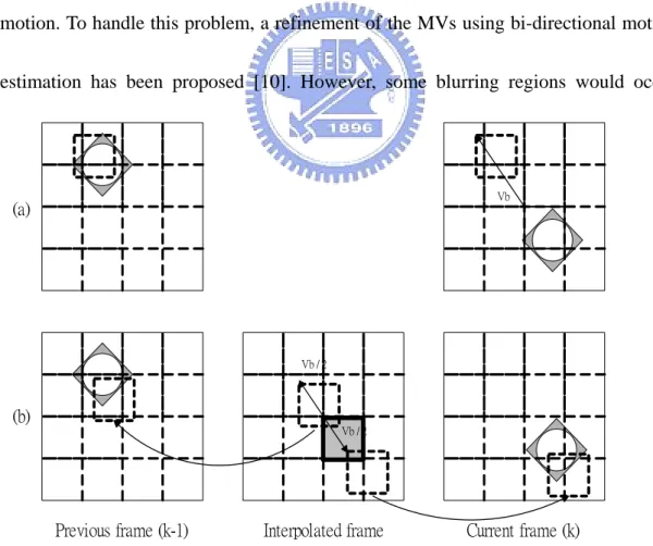
by block. To find the blocks in the (k-1)th (previous) and kth (current) frames to be
used for interpolation, start with the estimated motion vector (Vb), as shown in Fig.
1-2(a). Using the assumption of linear motion , we estimate that each block will have
moved one half of its motion vector distance in the interpolated frame. Before
interpolating a block in the interpolated frame, one block from each of the (k-1)th
(previous) and kth (current) frames is searched as shown in Fig. 1-2(b). Although the
method can keep the overlapped and hole regions off, a new problem occurs. It is that
the motion of the compensated block is not always the same as the estimated block
motion. To handle this problem, a refinement of the MVs using bi-directional motion
estimation has been proposed [10]. However, some blurring regions would occur
Vb
Vb / 2
Previous frame (k-1) Interpolated frame Current frame (k)
Fig. 1-2 (a) Estimatied MV, Vb, computed during ME, (b) Interpolation using blocks from (k-1)th and kth frames.
(a)
(b)
since there are not similar enough blocks in motion estimation. Other methods to
estimate the MV field are hierarchical MCFI (HMCFI) [1,14-15]. An approach [1]
based on the Gaussian/Laplacian pyramid structures has been proposed to improve
visual quality of interpolated frames. It focuses on refinement of the MCFI based on a
hierarchical progressive video scheme. However, this method requires large and
complicated operators since frames are decomposed into lowpass and highpass
components and the operators are quite different at top, intermediate and bottom
levels. Beside the effect on the top level affects the quality of the interpolated frame
so much. In [1,10-11,13], the block used to compensate to the interpolated frame is
usually formed by a linear combination from two frames. It would introduce
incomplete or overlapped shadow in the interpolated frame, since the blocks picked to
combine are not exact the same.
In this thesis, a new FRC based on MCI algorithm is proposed. To avoid
unnatural shadow, we construct the interpolated frame by only referring to one frame.
To get a better visual perception, there is a threshold used to abandon the MVs that
provide a large prediction error. To solve the problems of overlapped and hole regions
that are introduced in motion compensation, a weighted average compensation
technique is employed to process the overlapped regions, and a block-based algorithm
the proposed method will be described. Experimental results will be presented in
CHAPTER 2
THE PROPOSED METHOD
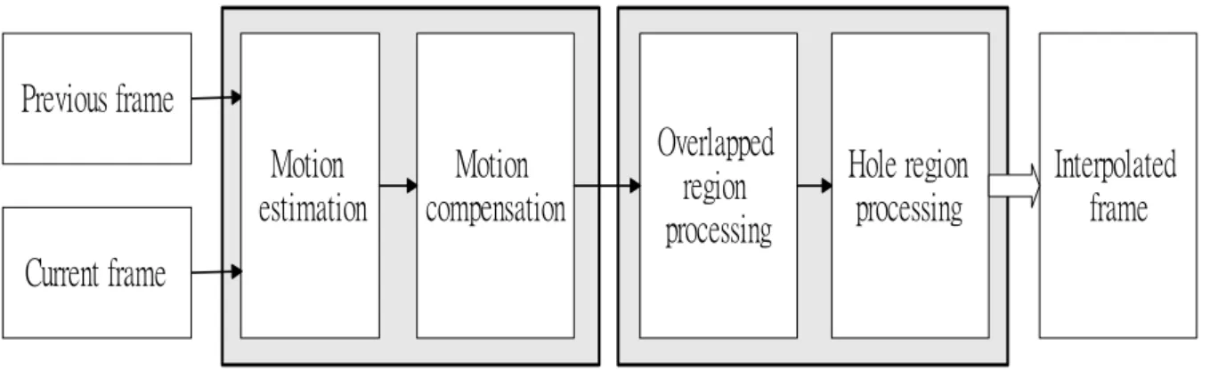
Fig. 2-1 shows the block diagram of the proposed method. It consists of two
phases: forward motion estimation and motion compensated interpolation, and
overlapped and hole regions processing. First, to determine how to interpolate the new
frame, the motion vectors are generated by forward motion estimation. Second, the
interpolation frame with motion vectors introduced from the first phase will be
constructed. Based on the natural perception, the information for interpolation only
refers to one frame. Third, the overlapped regions are processed by using the
weighted average compensation. Finally, we segment the interpolation frame into
blocks and compensate the hole regions block by block. In what follows, we will
describe the details of the proposed method.
Previous frame
Current frame
Motion
compensation
Overlapped
region
processing
Hole region
processing
Interpolated
frame
Motion
estimation
2.1 Motion estimation and motion compensated interpolation
A block matching algorithm is employed for forward motion estimation to obtain
the motion vectors. Let x be the spatial domain index, n be the time domain index,
and a frame image is denoted as f x( ,n). Then the motion vector, v, of a macroblock
(MB) is obtained by
{
}
{
}
{
}
⎩ ⎨ ⎧ > ≤ = ∈ ∈ ∈ t null t ) ( min if , ) ( min if , ) ( min arg S S S u u u v u u u ξ ξ ξ , (1) where∑
∑
∈ ∈ + − − = B B f n f n x x x u x u 1 )] , ( ) 1 , ( [ ) ( 2 ξ , (2)B is a macroblock in the search area, S is the search range of ME and t is a threshold
value for abandoning MVs. Note that if the motion of object is not linear, the
difference between the estimated macroblock and the macroblock in the related search
ranges will be large. That is, no appropriate motion vector can be found to estimate
the macroblock. To solve the above shortcoming, in this thesis, there is a threshold
used for abandoning this kind of motion vectors.
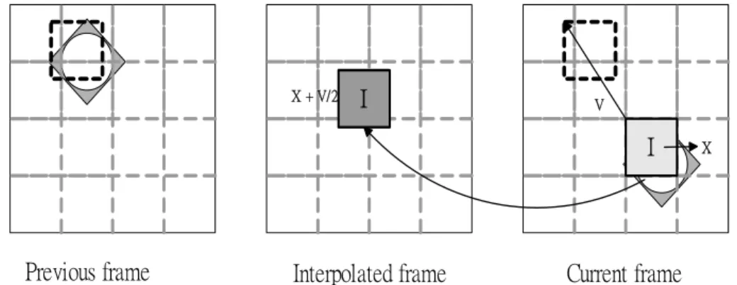
Fig. 2-2 shows how a frame is interpolated. For each macroblock I centered at x in
V
Previous frame Interpolated frame Current frame Fig. 2-2 Frame interpolation by the proposed method with Macroblock I inserted
X X + V/2
I I
frame n, we first find its motion vector v, then paste macroblock I in the interpolation
frame 2 1 −
n with center located at 2 v
x+ . That is the interpolated frame is
generated by ) , ( ) 2 1 , ( n f n f x 2 v x+ − = , (3)
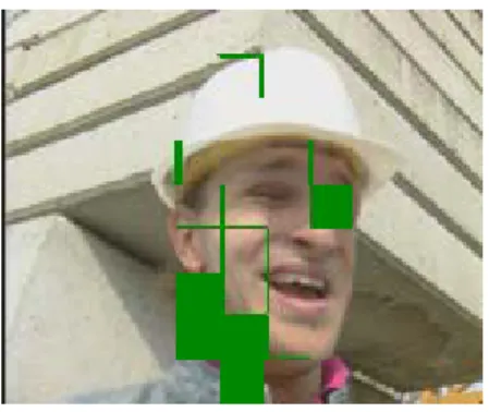
where v is the estimated motion vector. To avoid unnatural shadow and blurring, our
compensation only refers to one frame. Fig. 2-3 is an example of result after this step.
2.2 Overlapped and hole regions processing
Overlapped and hole regions are introduced in the interpolated frame since some
adjacent motion vectors are not the same. Moreover, some hole regions are produced
(a)
(b)
The overlapped regions
The hole regions
Fig. 2-3 (a) The previous and current frames. (b) The interpolated frame by the proposed motion estimation and motion compensated interpolation with frames of (a).
due to null motion vectors. Fig. 2-4 shows that the overlapped and hole regions are
introduced in the interpolated frame. In this thesis, we use a counter array to detect the
overlapped and hole regions [1]. Hole regions are pixels with the count value equal to
zero while overlapped regions are pixels with the count value larger than one. A
motion vector array is also needed for hole regions processing.
2.2.1 Overlapped region processing
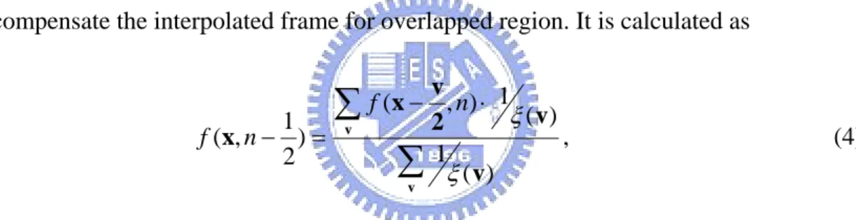
For reducing blocking artifact, we use a weighted average way [13] to
compensate the interpolated frame for overlapped region. It is calculated as
∑
∑
− ⋅ = − v v v v 2 v x x ) ( 1 ) ( 1 ) , ( ) 2 1 , ( ξ ξ n f n f , (4)where v is the motion vector of macroblock that covers the pixel x. That is, all motion
vectors of macroblocks covering the same location x are utilized. For processing hole
Fig. 2-4 Three types of blocks in the interpolation frame. Compensated completely block
Compensated block with partial hole region Complete hole block
Compensated Overlapped Hole
regions which will be described latter, a motion vector array is provided. For each
pixel x covered by several motion compensated blocks, the array will only store the
motion vector of the motion compensated block with minimum prediction error. As a
result, the motion vector array is filled with motion vectors except for hole regions.
Fig. 2-5 is an example of result after this step.
2.2.2 Hole region processing
To compensate the hole regions of the interpolated frame efficiently, the
interpolated frame will be divided into blocks of the same size and the hole regions
will be compensated block by block. Different kinds of blocks need different methods
to compensate the hole region. As shown in Fig. 2-4, there are three kinds of blocks:
compensated completely, compensated with partial hole region, complete hole region.
In what follows, we will introduce two kinds of methods to perform hole region
processing.
The hole regions
Fig. 2-5 The interpolated frame about Fig. 2-3(b) after processing of the overlapped regions by the proposed method.
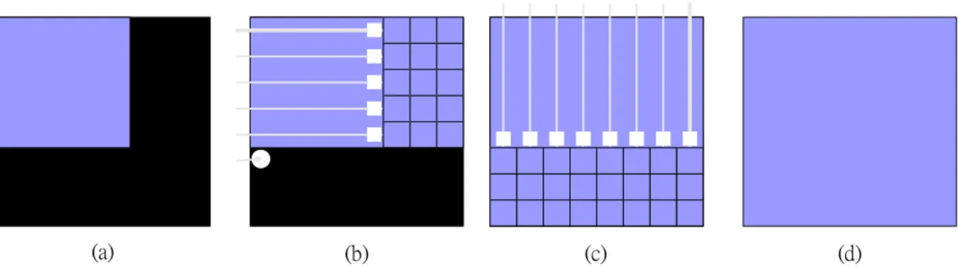
2.2.2.1 The process of block compensated with partial hole region
Fig. 2-6 shows the flow diagram of the compensated method. Basically, the
proposed algorithm detects the hole region in a block by scanning it row by row
(column by column), and compensates the hole region by the motion vector of the
adjacent pixel. The order of scanning direction and the start row (column) are shown
as in Fig. 2-7 respectively. As shown in Fig. 2-6(b), if the first pixel on a row (or
column) according to scan direction belongs to the hole region, stop the block scan
and rescan from a new direction according to the proposed order. In our experiment,
the effective scanning runs two directions at most. Since the second direction
scanning can compensate the hole region totally referring to the information
compensated in the first direction scanning if it needs (see Fig. 2-6(c)). Fig. 2-8 is an
example of result after this step.
(a) (b) (c) (d)
Fig. 2-6 (a) A block with partial hole region (black part). (b) Scan the block row by row, and stop scanning when the first scanned pixel in a row belongs to the hole region. (c) Change the scanning direction and scan the block column by column. (d) The compensated block.
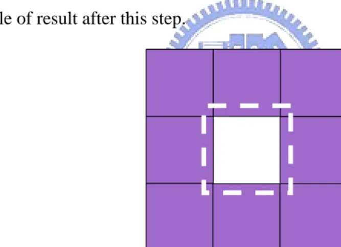
2.2.2.2 The processing of block with complete hole region
If the values of counter array on the four corners of a block are zeros, then the
block is a complete hole region. In this thesis, based on the motion information from
the block’s neighbors, we propose a method to decide the motion vector, v, of the
hole block (see Fig. 2-9). That is,
{
( )}
max arg u v u∈S N = , (5)where N(u) is the times of u occurring in S and S is the neighboring pixels around the
1(5)
2
3
4
Fig. 2-7 The order of the block scanning direction with bold arrow indicating the first scanning row (column).
The hole regions
Fig. 2-8 The interpolated frame about Fig. 2-5 after processing of the compensated block with the partial hole regions by the proposed method.
hole block and shown in Fig. 2-9. Fig. 2-10 is an example of result after this step.
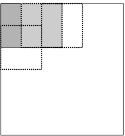
2.2.3 Motion estimation with overlapping
Since there are hole regions produced in motion compensation, overlapping
processing block would reduce the hole regions. A frame is divided into several
blocks with half block overlapping and each block is used to do motion estimation
and compensation, as shown in Fig. 2-11. Based on this overlapping schema, the
number of hole regions is reduced, and there are fewer blocking artifact. Fig. 2-12 is
an example of result after this step.
Fig. 2-10 The interpolated frame about Fig. 2-8 after processing of the complete hole block regions by the proposed method.
Fig. 2-11 Motion estimation using overlapping blocks.
The hole regions
Fig. 2-12 The interpolated frame about Fig. 2-3(a) after processing of the overlapped regions with half block overlapped.
CHAPTER 3
EXPERIMENTAL RESULTS
In this section, we present some experimental results. The experiments are
focused on doubling the frame rate. The size of the marcoblock is set as 16×16 and
the search range is ± 16 pixels for both horizontal and vertical directions. The
threshold for abandoning motion vectors in motion estimation is set as 400. We
select three different video sequences for testing. They are “calendar”, “foreman” and
“table”. Test sequences are color sequences with YUV 4:1:1 format. The image size of
test sequences is 176×144 quarter common intermediate format (QCIF). In order to
show the brief and efficiency of the proposed method, we compare the results with an
algorithm of hierarchical MCFI (HMCFI) [1].
3.1 Comparison with hierarchical MCFI
Fig. 3-1 is an example of scene with multiple motions. It contains camera
zooming and panning. There are also several object motions such as horizontal
translation (train), vertical translation (calendar) and rotation (ball). The speeds of
motions are not fast. As shown in Fig. 3-1, especially Fig. 3-1(e) and Fig. 3-1(f), the
the interpolated frame by HMCFI is usually compensated by two frames with
averaging while that by the proposed method is only compensated by one frame.
(a) (b)
(c) (d)
(e) (f)
Fig. 3-1 “Calendar" sequences : (a) previous frame, (b) current frame, (c) frame interpolated by the HMCFI, (d) frame interpolated by the proposed method, (e) an enlarged region of (c) by a factor of two, (f) an enlarged region of (d) by a factor of two.
Fig. 3-2 is an example of scene with motion of panning. The camera moves from
left to right and the scene shifts to right with a medium speed. Although the motion is
simple, some determinations of motion vectors are difficult. It is easy to find that
(a) (b)
(c) (d)
(e) (f)
Fig. 3-2 “Foreman" sequences : (a) previous frame, (b) current frame, (c) frame interpolated by the HMCFI, (d) frame interpolated by the proposed method, (e) an enlarged region of (c) by a factor of two, (f) an enlarged region of (d) by a factor of two.
there are two faulted macroblocks marked by circles compensated with faulted motion
vectors on the right-up corner in the interpolated frame by HMCFI. In this case, the
proposed method provides a more precise motion estimation and a better
compensation.
Fig. 3-3 is an example of scene with motion of zooming. The camera zooms
from the near to the distant and the scene becomes larger gradually. Among the frames,
the left hand moves fast. From Fig. 3-3(c), we can see that the shape of the left hand
in the HMCFI interpolated frame is blurred seriously, even the table and the hand are
indistinct. And the shape of the hand in the proposed interpolated frame approaches
(a) (b)
(c) (d)
Fig. 3-3 “Table" sequences : (a) previous frame, (b) current frame, (c) frame interpolated by the HMCFI, (d) frame interpolated by the proposed method without overlapping.
the original one. The poster on the left up corner in the interpolated frame by HMCFI
is more blurred than that in the proposed interpolated frame. This is due to that
HMCFI adapt to two average compensation blocks from two frames.
Fig. 3-4 shows the PSNR for the interpolated frames by the proposed method and
HMCFI method. In order to compute the PSNR of an interpolated sequence, we drop
the frames of even number on purpose and reproduce each dropping even frame by its
previous and next odd number frames. And then we compare the interpolated frames
with original ones. Fig. 3-4(a) is the result of the “foreman” sequence. The PSNRs of
the proposed method are a little lower than those of HMCFI. It is due to that the frame
constructed by the proposed method only refers to one frame. However, the
interpolated frame by the proposed method is clearer from the visual point. Fig. 3-4(b)
is the result of the “table”. The PSNR of the 67th interpolated frame by the proposed
method is much lower since a scene change appears here. From Fig. 3-4, we found
that PSNRs of both methods in most parts are similar. However, the proposed method
provides higher quality from visual point and is simpler than HMCFI.
3.2 Effectiveness of overlapping block
In order to reduce the hole regions produced from MC and the blocking artifact,
20 25 30 35 40 45 50 1 10 19 28 37 46 55 64 73 82 91 100 109 118 127 136 145 interpolated frames PSN R (d b )
the proposed method HMCFI
(a) 20 25 30 35 40 45 50 1 14 27 40 53 66 79 92 105 118 131 144 157 170 183 196 the interpolated frames
PSN
R
(d
b
)
the proposed method HMCFI
(b)
Fig. 3-4 The PSNR computation of the sequences: (a) the sequence of “foreman”, (b) the sequence of “table”.
schema affects on the perceptual quality of the interpolated frame, we simulated two
types of frame rate up-conversion:
(a) the proposed method without overlapping block
(b) the proposed method with overlapping block
Fig. 3-5 shows that the perceptual quality is improved if the overlapping schema is
used. In Fig. 3-5(e) and 3-5(f), we can see that, the interpolated frame produced with
overlapping is smoother and has fewer block artifacts. It is obvious that the block
(a) (b)
(c) (d)
(e) (f)
Fig. 3-5 “Table"sequence: (a) previous frame, (b) current frame, (c) frame interpolated by the proposed method without overlapping, (d) frame interpolated by the proposed method with overlapping, (e) and (f) enlarged regions of (c) and (d) by a factor two, respectively.
CHAPTER 4
CONCLUSIONS
In this thesis, we have presented a new motion compensated interpolated
algorithm for frame rate up-conversion. The proposed method consists of two
component: forward motion estimation and motion compensation, and overlapped and
hole regions processing. To get a naturally perceptual and non-blur scene, two new
concepts are provided. The motion vectors are abandoned when the prediction errors
are too large, and the process of compensation only refers to one frame. Moreover,
overlapping blocks make the hole regions fewer and the compensation precisely.
REFERENCES
[1] B.-W. Jeon, G.-I. Lee, S.-H. Lee, and R.-H. Park, “Coarse-to-Fine Frame
Interpolation for Frame Rate Up-Conversion Using Pyramid Structure,” IEEE
Trans. Consumer Electronics, vol. 49, no. 3, pp. 499-508, Aug. 2003.
[2] K. A. Bugwadia, E. D. Petajan, and N. N. Puri, “Progressive-Scan Rate
Up-Conversion of 24/30 Source Materials for HDTV,” IEEE Trans. Consumer
Electronics, vol. 42, no. 3, pp. 312-321, Aug. 1996.
[3] S. C. Han and J. W. Woods, “Frame-rate Up-conversion Using Transmitted Motion
and Segmentation Fields for Very Low Bit-rate Video Coding,” in Proc. Int. Conf.
Image Processing, vol. 1, pp. 747-750, Oct. 1997.
[4] ITU-T Recommendation H.263, Video Coding for Low Bit-Rate Communications.
Nov. 1995.
[5] ISO/IEC JTC1/SC29/WG11 MPEG93/N457, MPEG-2 Test Model Version5. Mar.
1993.
[6] J. N. Youn, M. T. Sun, and C. W. Lin, “Motion estimation for high performance
transcoding,” IEEE Trans. Consumer Electronics, vol. 44, no. 3, pp. 649-658,
1998.
[7] G. D. Haan, P. W. A. C. Biezen, H. Huijgen, and O. A. Ojo, “True-motion
Video Technol., vol. 3, no. 5, pp. 368-379, Oct. 1993.
[8] F. Dufaux and F. Moscheni, “Motion estimation techniques for digital TV: A review
and a new contribution,” Proc. IEEE, vol. 83, pp. 858-876, June. 1995.
[9] S.-H. Lee, Y.-C. Shin, S.-J. Yang, H.-H. Moon, and R.-H. Park, “Adaptive motion
compensated interpolation for frame rate up-conversion,” IEEE Trans. Consumer
Electronics, vol. 48. no. 3, pp. 444-450, Aug. 2002.
[10] B.–T. Choi, S.–H. Lee, and S.–J. Ko, “New frame rate up-conversion using
bi-directional motion estimation,” IEEE Trans. Consumer Electronics, vol. 46, no.
3, pp. 603-609, Aug. 2000.
[11] K. Hilman, H.–W. Park, and Y.-M. Kim, “Using motion compensated frame-rate
conversion for the correction of 3:2 pulldown artifacts in video sequences,” IEEE
Trans. Circuits Syst. Video Technol., vol. 10, no. 6, pp. 869-877, Sept. 2000.
[12] R. Castagno, P. Haavisto, and G. Ramponi, “A method for motion adaptive frame
rate up-conversion,” IEEE Trans. Circuits Syst. Video Technol., vol. 6, no. 5, pp.
436-446, Oct. 1996.
[13] S.-H. Lee, O. Kwon, and R.-H Park, “Weighted-Adaptive Motion-Compensated
Frame Rate Up-Conversion,” IEEE Trans. Consumer Electronics, vol. 49, no. 3,
pp. 485-492, Aug. 2003.
covered and uncoverd background,” Signal Processing: Image Compression, vol.
1, pp. 192-212, 1989.
[15] M. Bierling and R. Thoma, “Motion Compensating field interpolation using a
hierarchically structured displacement estimator,” Signal Processing, vol. 11, no. 4,