微光學制動DMD技術設計光纖光柵訊號讀取系統(2/2)
13
0
0
全文
(2) 中文摘要. 本研究發展一套利用德州儀器數位微影像晶片(DMD Chip)技術之光源頻譜合成系統,將光 纖通訊用之EDFA光源(波段1530nm-1565nm)合成各種頻譜波形,其技術特點為利用一光柵將 光源頻譜分開,透過數位控制晶片技術與本研究發展之新頻譜合成原理與光譜波形校正技術 即可合成任意波形。在結果中我們將光源頻譜合成方波、三角波與鋸齒波。此技術完全以數 位控制,穩定度高、速度快,非常適合各種應用,如FBG、感測器結果分析,光頻譜掃描與 頻譜濾波器等應用。. II.
(3) Abstract This study presents a digital programmable light spectrum synthesis system based on the Digital Micromirror Device (DMDTM) from Texas Instruments (TI). A DMD pattern scanning calibration method is developed and applied to the synthesis of various infrared C-band (1530-1565 nm) spectral profiles, including a fast programmable tunable light source, a square profile, a saw tooth waveform and a triangular spectrum profile The experimental results show that the wavelength resolution of the DMD spectrum synthesis system is approximately 0.076 nm/pixel. The proposed spectrum synthesis system has a number of key advantages, including a rapid and stable performance and multi-channel compatibility. The spectrum synthesis system is suitable for various applications, including a tunable light source, an equalizer for erbium-doped fiber amplifiers (EDFAs), and a wavelength scanner.. III.
(4) Digital programmable light spectrum synthesis system using a digital micromirror device C. H. Chuang and Y. L. Lo. We present a digital programmable light spectrum synthesis system based on a digital micromirror device (DMD) from Texas Instruments. A DMD pattern-scanning calibration method is developed and applied to the synthesis of various infrared C-band (1530 –1565 nm) spectral profiles, including a fast programmable tunable light source with a bandwidth of approximately 3.8 nm, a square profile, a sawtooth waveform, and a triangular spectrum profile. The experimental results show that the wavelength resolution of the DMD spectrum synthesis system is approximately 0.076 nm兾pixel. The proposed spectrum synthesis system has a number of key advantages, including a rapid and stable performance and multichannel compatibility. The spectrum synthesis system is suitable for various applications, including pulse shaping for coherent control and harmonic generation, a tunable light source, an equalizer for erbium-doped fiber amplifiers, and a wavelength scanner. © 2006 Optical Society of America OCIS codes: 230.3990, 300.6380.. 1. Introduction. Digital micromirror device (DMD) chips are most commonly applied in commercial digital light processing (DLP) projector engines. However, various other applications have also been proposed,1–3 including near-infrared spectrometry, and programmable array microscopy. The Riza group has proposed many potential applications of DMD chips in optical fiber communications. For example, in an early study, they developed a high-density multiwavelength add– drop filter using a two-dimensional DMD chip.4 The proposed filter featured a polarization-insensitive operation, low interchannel cross-talk parallel processing, and a fault-tolerant design. In later studies, Riza and Sumriddetchkajorn5,6 simplified their original system and applied the macropixel concept to develop an optical wavelength division multiplexing (WDM) attenuator. Walter et al.7 presented a dynamic optical filter for dense wavelength division multiplexing (DWDM) systems. The authors reported that the. The authors are with the National Cheng Kung University, Tainan 701, Taiwan. C. H. Chuang is with the Department of Mechanical Engineering. Y. L. Lo ([email protected]) is with the Department of Mechanical Engineering and the Advanced Optoelectronic Technology Center. Received 16 March 2006; revised 3 July 2006; accepted 3 July 2006; posted 5 July 2006 (Doc. ID 69033). 0003-6935/06/328308-07$15.00/0 © 2006 Optical Society of America 8308. APPLIED OPTICS 兾 Vol. 45, No. 32 兾 10 November 2006. DMD functions as a two-dimensional switched blazed grating (SBG) when modulating coherent light beams. In 2002, Sumriddetchkajorn and Riza8 and Sumriddetchkajorn9 designed a digitally controlled optical beam profiler, thereby making possible the realization of a number of different beam profile measurement concepts. A year later, Riza and Mughal10 combined the DMD macropixel concept with a high spectral resolution broadband transmissive volume Bragg grating to design a broadband optical equalizer. In the proposed system, a light beam was separated by the grating into its constituent wavelengths and the number of pixels in the wavelength macropixels was selected in order to control the spectral intensity. The system design hypothesized the light beam to have a Gaussian distribution when deriving the optical system parameters used to obtain the wavelength and intensity information from the DMD chip. However, this assumption is not realistic in practice and therefore creates difficulties in obtaining a precise spectrum profile shape. This study extends the concept presented by Riza and Mughal in Ref. 10 and uses ZEMAX software to design a transmissive-type light spectrum synthesis system. Uniquely, this study develops a DMD pattern scanning calibration method, which eliminates the requirement for a Gaussian spectral distribution and a precise alignment of the DMD chip. In the proposed approach, the DMD spectral distribution contour is obtained simply by scanning the DMD along the X and Y axes, respectively, where the X axis corre-.
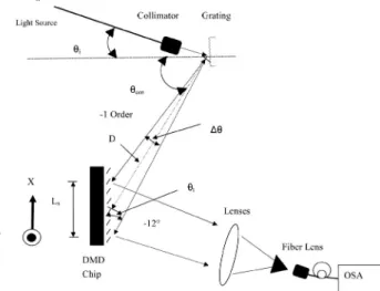
(5) Fig. 2. (Color online) Diffracted light incident on a DMD chip.. Fig. 1. Schematic of spectrum synthesis system.. sponds to the wavelength distribution of the spectrum and the Y axis to the intensity distribution. Adopting this approach, different light spectrum profiles can be synthesized precisely by modifying the DMD pattern following an initial DMD pattern scanning calibration routine. The spectrum synthesis system is suitable for various applications, including a pulse shaping for coherent control and harmonic generation,11,12 a tunable light source, an equalizer for erbium-doped fiber amplifiers (EDFAs), and a wavelength scanner. 2. Optical Design and Scanning Calibration A.. Optical Design. Figure 1 presents a schematic of the proposed programmable light spectrum synthesis system. In this optical arrangement, the white-light source is transmitted through a single-mode fiber (SMF), and the light emerging from the optical collimator is diffracted by a grating. The ⫺1-order diffractive light is incident on the DMD chip, where its reflective direction is governed by the direction of the micromirrors on the chip’s surface. In general, the micromirrors on a DMD chip have two ON–OFF bistable states (i.e., 12° and ⫺12°, respectively), which control the incident light such that it is reflected from the DMD surface in one of two different reflective directions.3 In the present configuration, the ⫺12° state reflective light is collected and focused on the fiber lens through an arrangement of biconvex and biconcave lenses. The spectrum synthesis results are then obtained using an optical spectrum analyzer (OSA). The collimated light incident on the grating is diffracted according to the following formula: n ⫽ d共sin d ⫺ sin i兲,. (1). where n is the order of diffraction, d is the grating period, is the wavelength, d is the diffraction angle, and i is the incident angle with respect to the normal axis of the grating. As shown in Fig. 1, the ⫺1-order. diffracted light is incident on the DMD chip with an angle of cen with respect to the central wavelength 共cen兲. Therefore the diffractive spread angle, ⌬, from the grating is expressed as ⌬ ⫽ max ⫺ min ⫽ sin⫺1共⫺max兾d ⫹ sin i兲 ⫺ sin⫺1共⫺min兾d ⫹ sin i兲,. (2). where max and min are the ⫺1-order diffractive angles with respect to the maxima wavelength, max, and the minima wavelength min. Figure 2 illustrates the spectral distribution of the diffracted light incident on the DMD chip. The spectral spread length, Lx, at the DMD chip along the diffractive direction (i.e., the X-axis direction) is given by Lx ⬵ D ⫻ ⌬兾sin t,. (3). where D is the distance from the grating to the DMD chip and t is the DMD tilt angle with respect to the diffracted light axis. In the orthogonal direction (i.e., the Y-axis direction), since an assumption is made that the beam propagates in parallel, the spread length can be expressed as Ly ⬵ w,. (4). where w is the light beam waist after it exits the fiber collimator. Therefore the X axis corresponds to the spectral distribution and the Y axis to the intensity distribution. From the above, the DMD chip micromirror resolution of wavelength R is given by R ⫽ 共max ⫺ min兲兾共Lx兾p兲,. (5). where p is one pixel side length, such that 共Lx兾p兲 gives the total number of pixels in the X-axis direction. The micromirrors on the DMD chip reflect the diffracted light in two different directions because they each have two ⫾12° states, which are controlled by the DMD pattern. When the micromirror state is set to ⫺12° (i.e., the OFF state), the diffracted light from 10 November 2006 兾 Vol. 45, No. 32 兾 APPLIED OPTICS. 8309.
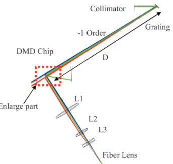
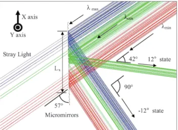
(6) Fig. 3. String-line pattern scans along the X and Y axes of a DMD chip.. this particular pixel is collected by the fiber lens as illustrated in Fig. 1. Therefore a synthesized spectrum can be obtained by adjusting the pattern of the DMD chip where the diffraction light is incident. B.. Digital Micromirror Device Chip Scanning Calibration. If all of the micromirrors on the DMD chip are set to ⫺12°, all of the ⫺1-order diffracted light on the DMD chip is reflected into the fiber lens. To calibrate the relationship between the diffraction wavelength and the X-axis coordinates of the DMD chip, a string-line pattern is scanned along the X-axis direction. Similarly, the diffraction intensity is calibrated by scanning a string-line pattern along the Y-axis direction. Figure 3 illustrates both string-line pattern scans along the X and Y axes in the DMD chip. The spectrum corresponding to an individual DMD pixel is expressed as F共s, i兲 ⫽ D共xm, yn兲,. (6). where F共s, i兲 is the calibrated light spectrum, s is the spectrum, i is the intensity, and D共xm, yn兲 are the DMD pixel coordinates. If the spectrum on the DMD chip has a Gaussian10 or uniform distribution, the intensity distribution along the Y axis is easily obtained. However, these conditions do not always hold. Therefore string-line pixel scans are performed along the X and Y axes, respectively, to obtain the twodimensional spectrum distribution on the DMD chip. From Eq. (6), the light spectrum synthesis principle is given by S共s, i兲 ⫽ 兺 关D共xm, yn兲␦共xm, yn兲兴,. (7). where S共s, i兲 is the synthesized light spectrum and ␦共xm, yn兲 is the ON–OFF state of the DMD pixels. When the micromirror state is ⫺12° (i.e., the ON state), ␦共xm, yn兲 ⫽ 1; otherwise ␦共xm, yn兲 ⫽ 0.. Fig. 4. (Color online) ZEMAX simulation of the light spectrum synthesis system.. cannot be specified as a continuous spectrum, this study specified a light source with an infrared C-band Gaussian spectrum distribution with three different wavelengths, i.e., min ⫽ 1530 nm, cen ⫽ 1550 nm, and max ⫽ 1565 nm. The simulations assumed the following: (i) a collimated light beam waist of w ⫽ 1 mm, (ii) a telecommunication grating with a grating period of 1.667 m, (iii) a light diffracted order of ⫺1, and (iv) an incident angle of i ⫽ 45°. Therefore from Eqs. (1) and (2), respectively, it was found that the ⫺1-order diffracted angle was cen ⫽ ⫺12.879° and the spread angle was ⌬ ⫽ 1.235°. The distance between the grating and the DMD chip, D, was set at 250 mm. As shown in Fig. 4, lenses L1, L2, and L3 focused the ⫺12° state diffracted light from the DMD into the fiber lens. The system parameters analyzed by the ZEMAX simulations were then used to establish an experimental setup for a digital programmable light spectrum synthesis system. Figure 5 presents an enlarged view of the DMD chip shown in Fig. 4. As shown, the chip is tilted at an angle of 57° about the light axis. As discussed previously, the micromirrors on the DMD chip have ⫾12° states. In the present simulations, the micromirrors at either end of the DMD chip were set to ⫺12° (i.e., the OFF state), causing the incident light to be reflected through an angle of 90°. Meanwhile, the micromirrors in the central region of the DMD were set to the 12° state (i.e., the ON state), causing the incident light to be reflected at an angle of 42°. From Eqs. (3) and (4), respectively, the X-axis spread length was found to be Lx ⫽ 6.425 mm and the Y-axis spread length to be w ⫽ 1 mm.. 3. ZEMAX Simulation of the Light Spectrum Synthesis System. 4. Experimental Setup and Calibration. Figure 4 presents a schematic of the light spectrum synthesis system simulated using the ZEMAX optical design software. Since in ZEMAX, the light source. A.. 8310. APPLIED OPTICS 兾 Vol. 45, No. 32 兾 10 November 2006. Experimental Setup. The light source in the present experiments was an amplified spontaneous emission (ASE) from an.
(7) Fig. 5. Enlarged view of a DMD chip region of the light spectrum synthesis system.. EDFA with a center wavelength of cen ⫽ 1550 nm and a spectral bandwidth of ⌬ ⫽ 37 nm. As shown in Fig. 6, the light source has two peaks and therefore does not conform to a simple Gaussian distribution. Figure 7 presents a photograph of the experimental setup of the light spectrum synthesis system designed in accordance with the ZEMAX simulation results. The current optical arrangement used an Optometrics LLC telecommunication grating (catalog no. 3-4616) with a period of 1.667 m and a blaze angle of 28°41’. The typical efficiency of this grating for a wavelength of 1550 nm is approximately 80%. From Rayleigh’s criterion, the grating’s resolution limit was calculated to be 1.826 nm at cen. The DMD chip controller module (PSI Discovery 1100 starter kit) in the experimental setup used a Texas Instruments 0.7 in. (1 in. ⫽ 2.54 cm) infrared DMD chip consisting of a 1024 horizontal ⫻ 768 vertical array of aluminum micromechanical mirrors with a transition time of 20 s arranged with a pitch of 13.68 m. The patterns on the DMD chip were manipulated using graphical user interface software (Version 1.3) and a USB interface. The frame rate of the DMD chip. Fig. 6. ASE spectrum from EDFA.. Fig. 7. (Color online) Experimental setup of the light spectrum synthesis system.. was 100 frames兾s with a standard USB 2.0 interface, but was improved to 4000 frames兾s using an accelerative board. Focusing lenses L1 and L2 (see Fig. 4) were biconvex spherical lenses with focal lengths of 100 and 50 mm, respectively. Meanwhile, L3 was a biconcave spherical lens with a focal length of ⫺50 mm. The fiber lens (LPF-05-1550-9, OZ Optics Ltd.) had a focal length of 1.99 mm and a working distance of 1.5 mm. The OSA is an HP 70952B and its resolution is 0.065 nm ⫾ 15% at FWHM. B.. Calibration of the Light Spectrum Synthesis System. Figure 8 presents the light spectrum collected by the fiber lens when all of the micromirrors on the DMD chip are set to the ⫺12° state. In the calibration process, DMD string-line patterns are scanned step by step along the X axis, as shown in Fig. 3. Each string-line pattern consists of 30 micromirror columns. If too few micromirror columns are included within the string-line pattern, a serious diffraction effect is induced because the column pattern resembles a single slit. Conversely, if too. Fig. 8. DMD reflected light spectrum captured by a fiber lens. 10 November 2006 兾 Vol. 45, No. 32 兾 APPLIED OPTICS. 8311.
(8) with the results presented in Section 3. The area shown in Fig. 10 contains 40,500 pixels, i.e., just 1兾20 of the total number of pixels on the DMD chip. Hence the potential exists to design a multichannel system. Finally, the contour can be used to synthesize different spectra by applying Eq. (7). Four light spectrum synthesis examples are presented for illustration purposes in the following section. 5. Illustrative Examples of Synthesized Spectra and Discussion. Fig. 9. Relationship between the diffracted light wavelength and DMD X-axis pixel coordinates.. many micromirror columns are included, the resolution will be poor. Figure 9 illustrates the relationship between the diffracted light wavelength and the DMD X-axis pixel coordinates as obtained by X-axis string-line pattern scanning. From Eq. (5), the DMD chip wavelength resolution R is found to be 0.076 nm兾pixel. Since the spread of the light diffracted in the Y-axis direction is narrow [from Eq. (4), Ly ⫽ w ⫽ 1 mm], the scan period must be shorter than that used for the X-axis scanning to enhance the intensity resolution. A 10-pixel 共136.8 m兲 string-line pattern was found to induce a serious diffraction effect, and hence scanning was performed using a string-line pattern with an average value of 30 pixels. For example, the intensity in row 45 represents the average recorded intensity over rows 31 to 60 (i.e., 30 pixels in total). Although the measured values of intensity therefore indicate the relative intensity rather than the absolute intensity, the results nevertheless provide a good indication of the actual intensity. The relationships between the DMD micromirror coordinates and the wavelength and intensity, respectively, were used to draw the contour of F共s, i兲 ⫽ D共xm, yn兲 as illustrated in Fig. 10. It can be seen that the contour has two peaks, i.e., at 1545 and 1534 nm, respectively, as expected from Fig. 8. Furthermore, the results of Lx ⫽ 450 pixels ⫻ 13.68 m ⫽ 6.156 mm and Ly ⫽ 90 pixels ⫻ 13.68 m ⫽ 1.23 mm are consistent. Fig. 10. Contour of diffracted light incident on a DMD chip. 8312. APPLIED OPTICS 兾 Vol. 45, No. 32 兾 10 November 2006. Figure 11(a) shows a square spectrum profile synthesized by the calibration pattern presented in Fig. 10. It can be seen that the spectrum is poorly defined because the 30-pixel string-line scanning pattern is not sufficiently precise. However, the DMD pattern can be simply and quickly tuned according to the contour shown in Fig. 10. The wavelength and intensity of the synthesis spectrum in Fig. 11(a) need to be checked and then the numbers of the DMD OFF-. Fig. 11. Synthesis of square spectrum profile: (a) initial profile and (b) profile following the DMD pattern adjustment..
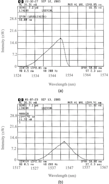
(9) Fig. 13. DMD rapid programmable tunable light source with three center wavelengths, i.e., 1531.50, 1542.00, and 1552.25 nm.. Fig. 12. DMD programmable spectral profile synthesis results: (a) sawtooth profile and (b) triangular profile.. state pixel can be slightly added or subtracted according to Fig. 10 until the spectrum becomes Fig. 11(b). Figure 11(b) shows the square spectrum profile following an adjustment of the DMD pattern. It is apparent that the flatness of the profile is greatly improved. Note that the edge of the synthesized spectrum can be improved by increasing the grating resolution. Figure 12 shows the synthesis results obtained for a sawtooth spectrum profile [Fig. 12(a)] and a triangular spectrum profile [Fig. 12(b)]. It can be seen that the original synthesized spectra obtained using the calibration contour in Fig. 10 must be corrected by adjusting the DMD chip pattern. As in the example presented in Fig. 11, not only the spectrum but also the intensity corresponding to each pixel must be manipulated. The methodology that we discuss above can be applied to a rapid programmable tunable light source by exploiting the relationship between the pixel coordinates and the wavelength. Since the spectrum in a. programmable tunable light source has a simple synthesized Gaussian distribution, the calibration relationship in Fig. 9 is sufficient. Figure 13 shows an example of a programmable tunable light source with three center wavelengths, i.e., 1531.50, 1542.00, and 1552.25 nm, where each wavelength has a bandwidth of approximately 3.8 nm. From above, the wavelength bandwidth in the system could be narrowed by using a proper grating and optical design, for example, increasing the grating resolution, increasing the distance D (as illustrated in Fig. 1), or reducing the scanning DMD pixel number. However, the diffractive effect should be considered when fewer scanning DMD pixel numbers are applied. In general, the results presented in Figs. 11–13 indicate that a spectrum with a Gaussian distribution (as illustrated in Fig. 13) can be synthesized simply by applying the calibration relationship illustrated in Fig. 9. However, if synthesizing the spectrum involves manipulating not only the spectrum wavelength but also the intensity, the calibration contour in Fig. 10 must be applied. Due to the lower resolution of the intensity distribution calibration, a further correction of the DMD chip pattern is also required. 6. Conclusions. This study has applied the results obtained from the ZEMAX optical design software to develop a digital programmable light spectrum synthesis system based on the digital micromirror device chip from Texas Instruments. It has been shown that this chip provides a wavelength resolution of 0.076 nm兾pixel. In contrast to the spectrum synthesis system presented in Ref. 10, the current approach does not insist that the light source spectrum must have a Gaussian distribution. The two-dimensional spectral and intensity distribution of the spectral profile is calibrated by scanning Xand Y-string-line patterns across the light spot on the DMD. Any spectral profile can then be synthesized by applying the relationship between the spectrum and 10 November 2006 兾 Vol. 45, No. 32 兾 APPLIED OPTICS. 8313.
(10) the micromirror coordinates. The technique proposed in this study is fully digitally programmable and provides a simple and versatile means of synthesizing various light patterns. Hence it is suitable for application in optical communication systems, sensing systems, and fluorescence microscopy. The authors gratefully acknowledge the financial support provided to this study by the National Science Council, Taiwan, under grant NSC 93-2212-E-006-093. Also, funding from the Advanced Optoelectronic Technology Center, National Cheng Kung University under projects from the Ministry of Education and the National Science Council (NSC 95-219-M-009-008) of Taiwan is gratefully acknowledged. References 1. R. A. Deverse, R. M. Hammaker, and W. G. Fateley, “Realization of Hadamard multiplex advantage using a programmable optical mask in a dispersive flat-field near-infrared spectrometer,” Appl. Spectrosc. 54, 1751–1758 (2000). 2. Q. S. Hanley, P. J. Verveer, M. J. Gemkow, D. Arndt-Jovin, and T. M. Jovin, “An optical sectioning programmable array microscope implemented with a digital micromirror device,” J. Microsc. 96, 317–331 (1999). 3. L. J. Hornbeck, “Digital light processing for high-brightness, high-resolution applications,” Texas Instruments, 12 February 1997, http://www.dlp.com/dlp_technology/images/dynamic/ white_papers/141_hornbeck.pdf. 8314. APPLIED OPTICS 兾 Vol. 45, No. 32 兾 10 November 2006. 4. N. A. Riza and S. Sumriddetchkajorn, “Fault-tolerant dense multiwavelength add– drop filter with a two-dimensional digital micromirror device,” Appl. Opt. 37, 6355– 6361 (1998). 5. N. A. Riza and S. Sumriddetchkajorn, “Digital controlled faulttolerant multiwavelength programmable fiber-optical attenuator using a two-dimensional digital micromirror device,” Opt. Lett. 24, 282–284 (1999). 6. S. Sumriddetchkajorn and A. N. Riza, “Fault-tolerant threeport fiber-optic attenuator using small tilt micromirror device,” Opt. Commum. 205, 77– 86 (2002). 7. M. D. Walter, B. Terry, L. Benjamin, P. Don, R. Paul, and S. Bryce, “Dynamic optical filter in DWDM systems using the DMD,” Solid-State Electron. 46, 1583–1585 (2002). 8. S. Sumriddetchkajorn and A. N. Riza, “Micro-electromechanical system-based digitally controlled optical beam profiler,” Appl. Opt. 41, 3506 –3510 (2002). 9. S. Sumriddetchkajorn, “Micromechanics-based digitally controlled tunable optical beam shaper,” Opt. Lett. 28, 737–739 (2003). 10. A. N. Riza and M. J. Mughal, “Broadband optical equalizer using fault-tolerant digital micromirrors,” Opt. Express 11, 1559 –1565 (2003). 11. J. Ye, S. T. Cundiff, S. Foreman, T. M. Fortine, T. L. Hall, K. W. Holman, D. J. Jones, J. D. Jost, H. C. Kapteyn, K. A. H. V. Leeuwen, L. S. Ma, M. M. Murnane, J. L. Peng, and R. K. Shelton, “Phase-coherence synthesis of optical frequencies and waveforms,” Appl. Phys. B 74, S27–S34 (2002). 12. M. Dantus and V. V. Lozovoy, “Experimental coherent laser control of physicochemical processes,” Chem. Rev. 104, 1813– 1859 (2004)..
(11) 相關著作. 期刊論文 1.. Chuang, C. H. and *Lo, Y.L., “Digital Programmable Light Spectrum Synthesis System Using the Digital Micro-mirror Device,” Applied Optics, Vol. 45, No. 32, pp. 8308-8314, November 2006. (IF: 1.637); 17/55 (Optics). (獲選為國際知名期 刊 Applied Optics 的 11 月份封面介紹, 對台灣學術能見度有一定地提昇). 研討會論文 1.. 莊錦和、*羅裕龍, "DMD 晶片式光源頻譜合成系統,” 光學元件與系統設計 E1N-48418,2005 台灣光電科技研討會. 2.. 莊錦和、*羅裕龍, “DMD 晶片可程式化光源頻譜濾波系統,” 新興工程技術, pp. 1177-1182,2005 中國機械工程師學會第二十二屆全國學術研討會. 3.. Chuang, C.H. and *Lo, Y.L., “Using Digital Micromirror Device for Digital Programmable Light Spectrum Synthesis System,” Accepted by Society of Experimental Mechanics Annual conference, 2006. 莊 錦 和 、 * 羅 裕 龍 " Using the Digital Micromirror Device for Digital Synthesizing Light Spectrum", E10-007 2006 中國機械工程師學會第二十三 屆全國學術研討會. 4..
(12) 計畫成果自評 本計畫執行所得之成果架構符合當初之實驗架構,但應用方面和當初設定之 FBG 訊號分析儀器更為擴展為光源頻譜合成系統,可針對任意對光源之頻譜進行 各種波形之合成,應用面相當廣泛如:光纖通訊、雷射頻譜合成、單光儀、頻譜 分析儀等。其技術之成果更為知名期刊 Applied Optics 獲選為當期之封面介紹 (詳見附錄),可見本計畫所得之成果深受重視,相關之研究也持續進行。. 本計畫之技術將下一步將應用於近場光學顯微技術,利用光源頻譜合成技術 得到不同之近場光學影像,加以分析即可得知量測樣品針對不同之頻譜所產生之 樣品特性,相當具有研究價值,因此,國科會所支持本計畫所得技術與衍生之研 究相當豐碩。.
(13) 附錄.
(14)
數據
+2
Outline
相關文件
(4) 要獲得清楚的影像,請使用準直器順時針 /逆時針旋轉開關 、準直器垂直葉 片開啟 /閉合開關 、準直器水平葉片開啟 /閉合開關
其他光學儀器及設備製造業 從事 2771 細類以外光學儀器及設 備製造之行業,如望遠鏡、顯微
A factorization method for reconstructing an impenetrable obstacle in a homogeneous medium (Helmholtz equation) using the spectral data of the far-field operator was developed
A factorization method for reconstructing an impenetrable obstacle in a homogeneous medium (Helmholtz equation) using the spectral data of the far- eld operator was developed
In Section 3, the shift and scale argument from [2] is applied to show how each quantitative Landis theorem follows from the corresponding order-of-vanishing estimate.. A number
One way to select a procedure to accelerate convergence is to choose a method whose associated matrix has minimal spectral radius....
One way to select a procedure to accelerate convergence is to choose a method whose associated matrix has minimal spectral
We will give a quasi-spectral characterization of a connected bipartite weighted 2-punctually distance-regular graph whose halved graphs are distance-regular.. In the case the
