行政院國家科學委員會專題研究計畫 成果報告
功能梯度材料圓板或圓環承受橫向載重、徑向載重、或溫 度載重之力學分析
研究成果報告(精簡版)
計 畫 類 別 : 個別型
計 畫 編 號 : NSC 100-2221-E-011-099-
執 行 期 間 : 100 年 08 月 01 日至 101 年 07 月 31 日 執 行 單 位 : 國立臺灣科技大學營建工程系
計 畫 主 持 人 : 張燕玲
計畫參與人員: 碩士班研究生-兼任助理人員:杜鎮宇 碩士班研究生-兼任助理人員:李佩霞
公 開 資 訊 : 本計畫涉及專利或其他智慧財產權,1 年後可公開查詢
中 華 民 國 101 年 12 月 11 日
中 文 摘 要 : 本年度之研究主要以彈性理論為基礎,探討半徑為 R,厚為 h 之中等厚度 FGM 圓形板受到不同側向載重之力學行為。此 FGM 圓形板之邊界條件為簡支端。 而此 FGM 圓形板之材料性 質,則考慮沿著厚度方向呈 S 形函數變化。作用在此 FGM 圓 形板的側向載重,則考慮為(i) 均佈載重,(ii) 局部均佈載 重,(iii) 線性分佈載重,(iv) 二次分佈載重等四種形情。
首先,以彈性理論為基礎,建立 FGM 圓板之平衡方程式及諧 和方程式,再推導中等厚度之 FGM 圓板,在受到側向載重作 用下的通解;其次,求 FGM 圓板受到側向環載重之基本解,
再用積分求得不同側向載重下之理論解,進而探討撓曲、應 力、力矩等力學行為。結果顯示,FGM 圓形板受側向載重作 用下,其應力及彎曲力矩存在 之關係。另外功能梯度材料的 梯,以及載重形式對 FGM 圓板力學行為的影響亦有討論。
中文關鍵詞: FGM 圓板,側向載重,理論推導,有限元素法。
英 文 摘 要 : In this study, the closed-form bending solutions of simply-supported circular FGM plates subjected to linearly or quadratic, or partial uniform distributed loads are evaluated. The Poisson's ratios of the FGM plates are assumed to be constant, but their Young's moduli vary continuously throughout the thickness direction according to the volume fraction of constituents defined by sigmoid function. To solve the problem, the in-plane and bending problems of circular FGM plate are uncoupled first by properly choosing the origin of the z-axis such that the parameter . Then the fundamental bending solution of a simply-supported circular FGM plate under axi- symmetric ring-load is found based on the classical plate theory. Finally by superposing the fundamental solutions, the closed-form bending solutions of circular FGM plates under distributed transverse loads are determined and agree very well with the finite element calculation. Results reveal that the formulations of the bending solutions of FGM and homogeneous plates are similar, except the expression of the bending stiffness of plates. Moreover, the expressions of the closed-form solutions exist the relation of for the stresses and bending moments of the circular FGM plates. The effects of the steep of material gradient and the distribution of the
transverse load on the mechanical behaviors of the FGM plates are under investigation.
英文關鍵詞: FGM Circular Plate, Transverse Load, Theoretical Derivation, Finite Element Method.
行政院國家科學委員會專題研究計畫成果報告
功能梯度材料圓板或圓環承受橫向載重、徑向載重、或溫度載重之力學 分析(I):
FGMFGMFGM 圓板承受不同側向載重之理論推導與數值分析FGM圓板承受不同側向載重之理論推導與數值分析圓板承受不同側向載重之理論推導與數值分析圓板承受不同側向載重之理論推導與數值分析計畫編號: NSC 100-2221-E-011 -099
執行期限:
2011年
8月
1日至
2012年
7月
31日
Yen-Ling Chung, Professor of National Taiwan University of Science and Technology Pei-Xia Li and Zhen-Yu Du, Research Assistant
Key words: FGM circular plate, Fundamental problem, Analytical solution, Finite element solution
Abstract
In this study, the closed-form bending solutions of simply-supported circular FGM plates subjected to linearly or quadratic, or partial uniform distributed loads are evaluated. The Poisson’s ratios of the FGM plates are assumed to be constant, but their Young’s moduli vary continuously throughout the thickness direction according to the volume fraction of constituents defined by sigmoid function. To solve the problem, the in-plane and bending problems of circular FGM plate are uncoupled first by properly choosing the origin of the z-axis such that the parameter B11 =0 . Then the fundamental bending solution of a simply-supported circular FGM plate under axi-symmetric ring-load is found based on the classical plate theory. Finally by superposing the fundamental solutions, the closed-form bending solutions of circular FGM plates under distributed transverse loads are determined and agree very well with the finite element calculation. Results reveal that the formulations of the
bending stiffness of plates. Moreover, the expressions of the closed-form solutions exist the
relation of 2
11
( ) ( , )
(1 )
i i
zE z M i r
σ = v C = θ
− for the stresses and bending moments of the circular
FGM plates. The effects of the steep of material gradient and the distribution of the transverse load on the mechanical behaviors of the FGM plates are under investigation.
摘 摘 摘 摘 要 要 要 要
本年度之研究主要以彈性理論為基礎,探討半徑為 R,厚為 h 之中等厚度 FGM 圓 形板受到不同側向載重之力學行為。此 FGM 圓形板之邊界條件為簡支端。 而此 FGM 圓 形板之材料性質,則考慮沿著厚度方向呈 S 形 函 數 變化。作用在此 FGM 圓形板的側向 載重,則考慮為(i) 均佈載重,(ii) 局部均佈載重,(iii) 線性分佈載重,(iv) 二次分佈載 重等四種形情。首先,以彈性理論為基礎,建立 FGM 圓板之平衡方程式及諧和方程式,
再推導中等厚度之 FGM 圓板,在受到側向載重作用下的通解;其次,求 FGM 圓板受到 側向環載重之基本解,再用積分求得不同側向載重下之理論解,進而探討撓曲、應力、
力矩等力學行為。結果顯示,FGM 圓形板受側向載重作用下,其應力及彎曲力矩存在
2 11
( ) ( , )
(1 )
i i
zE z M i r
σ = v C = θ
− 之關係。另外功能梯度材料的梯,以及載重形式對 FGM 圓板
力學行為的影響亦有討論。
1. Introduction
Composite material is used to enhance the lifetime of materials due to the high
demands on the capabilities and operative life of materials. However, the stress singularities induced by the discontinuous character between the different layers may generate cracks and the composite medium thus becomes very susceptible to spallation. Thus, the concept of the
Functionally Graded Material (FGM) has been introduced to eliminate singular stresses [1,2], relax residual stresses[3], and enhance bonding strength.
Literatures corresponding to FGM plates have been rapidly increased recently, because the FGM may be applied to plate structure such as aircrafts, space vehicles, reactor vessels, and other engineering applications. Elastic bifurcation buckling of FGM plates under in-plane compressive loading was studied by Feldman and Aboudi [4], based on a combination of micromechanical and structural approaches. Praveen and Reddy [5] investigated the static and dynamic responses of functionally graded ceramic-metal plates by using a plate finite element that accounts for the transverse shear strains, rotary inertia and moderately large rotations in the Von Karman sense. He, Sivashanker and Ng [6] studied the vibration control of the FGM plates with integrated piezoelectric sensors and actuators by a finite element formulation based on the classical laminated plate theory. Woo and Meguid [7]applied the Karman theory for large deformation to obtain the analytical solution for the plates and shell under transverse mechanical loads and a temperature field. Vel and Batra [8] An analyzed three-dimensional thermo-mechanical deformations of a simply supported functionally graded rectangular plate subjected to time-dependent thermal loads on its top and/or bottom surfaces. The nonlinear response of functionally graded ceramic–metal plates (FGPs) under mechanical and thermal loads is investigated using the mesh-free kp-Ritz method was investigated by X. Zhao, K.M.
Liew [9] based on the first-order shear deformation plate theory and the von Karman strains.
Since circular FGM plates are also applied widely in many fields, the study of circular FGM plates have received much attention recently. Recep Gunes, Murat Aydin [10] studied three-dimensional impact behaviors of functionally graded (FG) circular plates under a drop-weight and indicated that the compositional gradient exponent, impact velocity and plate radius played an important role on the impact response of the FG circular plates, whereas the layer number through the plate thickness. M.M. Najafizadeh_, H.R. Heydari [11] studied
the mechanical buckling of circular FGM plates under uniform radial compression based on the higher order shear deformation plate theory (HSDT). Axisymmetric bending and buckling of perfect functionally graded solid circular plates are studied by A.R. Saidi, A.
Rasouli, S. Sahraee [12] based on the unconstrained third-order shear deformation plate theory (UTST). L.S. Ma a, T.J. Wang [13] applied the third-order shear deformation plate theory (TPT) to solve the axisymmetric bending and buckling problems of functionally graded circular plates. And relationships between the TPT solutions of axisymmetric bending and buckling of functionally graded circular plates and those of isotropic circular plates based on the classical plate theory (CPT) are presented.
Bending behavior is common in plate structure, therefore understanding the bending behavior of transversely functionally graded circular plates is important to assess the safety of the plate structure. X.Y. Li a, H.J. Ding a, W.Q. Chen [14] analyzed the bending of transversely isotropic circular plates with elastic compliance coefficients being arbitrary functions of the thickness coordinate, subject to a transverse load in the form of q r( )k. The non-linear axisymmetric and asymmetric behavior of functionally graded circular plates under transverse mechanical loading are investigated by Asghar Nosier, FamidaFallah [15]indicated that linear analysis is inadequate for analysis of simply supported FG plates which are immovable in radial direction even in the small deflection range, and the responses of FG materials under a positive load and a negative load of identical magnitude are not the same.
Based on three-dimensional theory, Wang Yun, Xu Rongqiao, Ding Haojiang [16] investigated the axisymmetric bending of transversely isotropic and functionally graded circular plates subject to arbitrarily transverse loads using the direct displacement method.
To the authors’ knowledge, no closed-form solution of circular FGM plates under transversely axisymmetric loads has been reported. In this paper, the closed-form solutions of circular FGM plates under axi-symmetrically distributed transverse loads are determined by
superposing the fundamental solutions. And the mechanical behaviors of simply-supported circular FGM plates subjected linearly or quadratic distributed loads, or partial uniform load are investigated.
2. Governing equations and general solution
2.1 Governing equations
Consider a linearly-elastic, moderately thick, circular FGM plate. It is assumed that the moderately thick FGM plat has a uniform thickness h in the range 1/ 20 ~ 1/100 of its radius approximately, and hence the transverse shear deformations can be neglected without causing significant errors Shames and Dym [17]. Further assume that the Young’s modulus of the circular FGM plate vary continuously only in the thickness direction (z-axis) i.e., E=E z( ),
however the Poisson’s ratio νis assumed to be constant in the FGM plate because the influence of Poisson’s ratio on the deformation of plates would be much less than that of the Young’s modulus as indicated by Delale and Erdogan [18].
Based on the assumptions of small deformation, the stress-strain relation of an FGM plate is:
0 0
2 2
2 2 2 2
( ) ( )
r 1 r
E z w w w
z v
v θ r r r r
σ ε νε
θ
∂ ∂ ∂
= − + − ∂ + ∂ + ∂ (1a)
0 0
2 2
2 2 2 2
( )
1 r
E z w w w
z v
v r r r r
θ θ
σ ε νε
θ
∂ ∂ ∂
= − + − ∂ + ∂ + ∂ (1b)
0
2
2 2
( ) 1
1 2 2
r r
E z w w
v z r r r
θ ν θ
τ γ
θ θ
− ∂ ∂
= − − ∂ ∂ − ∂ (1c)
where r0 u0 ε =∂r
∂ , 0 0 0
u v
r r εθ
θ
= + ∂
∂ , and r 0 0 0 0
u v v
r r r
γ θ
θ
∂ ∂
= + −
∂ ∂ are strains at the middle surface.
The quantitiesu x y0( , ),v x y0( , ),w x y( , ) are the displacements at the middle surface in the r-,
θ -, and z-directions.
The stress resultants per unit length of the middle surface are defined by integrating
stresses along the thickness. The in-plane axial forces Nr,Nθ,and Nrθ defined by
1 2
( r, , r ) h ( r, , r ) N N Nθ θ h σ σ τθ θ dz
=
∫
− and the bending moments per unit length of the middle surface, Mr , Mθ , and Mrθ defined by 12
( r, , r ) h ( r, , r ) M M Mθ θ h zσ zσθ zτ θ dz
=
∫
− areexpressed as:
0
11 0 11
0
1 0 1 0
1 0 1 0
1 1
0 0 0 0
2 2
r r r
r r r
N
N A B
N
θ θ θ
θ θ θ
ν ε ν κ
ν ε ν κ
ν γ ν κ
= +
− −
(2)
0
11 0 11
0
1 0 1 0
1 0 1 0
1 1
0 0 0 0
2 2
r r r
r r r
M
M B C
M
θ θ θ
θ θ θ
ν ε ν κ
ν ε ν κ
ν γ ν κ
= +
− −
(3)
where the coefficients Aij,Bij and Cij are the integration of the material properties of the
FGM plate and they are:
(
2)
11 11 11 2
( , , ) 1 ( ), ( ), ( )
A B C 1 E z zE z z E z dz
= ν
∫
− (4)and
2 r 2
w κ = −∂r
∂ ,
2
2 2
( w w )
r r r κθ
θ
∂ ∂
= − +
∂ ∂ ,
2
2( 2 )
r
w w
r r r
κθ
θ θ
∂ ∂
= − −
∂ ∂ ∂ are curvatures.
The equilibrium equations found by setting the vertical forces, the moments in radial
direction, and the moments in tangential direction equal to zero are [19]:
r r
z
V V V
r r r q θθ
∂ + +∂ = −
∂ ∂ (5)
r 2 r
M M M
r r r V
θ θ θ
θ θ
∂ + +∂ =
∂ ∂ (6)
r r
r
r
M M M
M V
r r r
θ θ
θ
− ∂
∂ + + =
∂ ∂ (7)
where Vr, Vθ are the shear forces in radial and tangential directions, respectively. By substituting Eqs. (6) and (7) into Eq. (5) and with the aid of Eq. (3), the equilibrium equation in the z direction expressed in Eq. (5) can be rewritten as:
3 2 2 2 3
0 0 0 0 0 0 0 0
11 3 2 2 3 3 2 3 2 3 3
3 3 2 3 3
0 0 0 0 0 0
2 2 2 3 2 2 2 2 3
4 2 3
11 4 2 2 3 3
( 2 )
1 2 2
( ) ( )
2 ( 2
u u u u v v u v
B r r r r r r r r r r r
u v v u u v u
v r r r r r r r r r r r
w w w w
C r r r r r r r
θ θ θ θ
θ θ θ θ θ
∂ − ∂ + ∂ + + ∂ − ∂ + ∂ + ∂ +
∂ ∂ ∂ ∂ ∂ ∂ ∂ ∂
∂ ∂ − ∂ ∂ ∂ ∂
+ + − + + +
∂ ∂ ∂ ∂ ∂ ∂ ∂ ∂ ∂ ∂
∂ ∂ ∂ ∂
+ − + − − −
∂ ∂ ∂ ∂
2 4 2 3 4
4 2 4 4 4 2 3 2 2 2 2
3 4 2
3 2 2 2 2 4 2
2 2 2 2
) ( )
1 4 4 4
2 ( z
w w w w w
r r v r r r r r
v w w w
r r r r r q
θ θ θ θ θ
θ θ θ
∂ − ∂ + − ∂ + ∂ − ∂
∂ ∂ ∂ ∂ ∂ ∂ ∂
− ∂ ∂ ∂
+ ∂ ∂ − ∂ ∂ − ∂ = −
(8)
It can be seen from Eqs.(2) and (3) that the in-plane and bending problems of the circular
FGM plate are coupled together. However, it is clear from Eqs.(2) and (3) that the in-plane
and bending problems of the circular FGM plate can be uncoupled if the parameterB11=0.
Chang and Chen [20] indicated that the parameterB is related to the first moment of the area 11
under the E z( ) curve with respect to the z=0 axis. And, if the origin of the z axis is
located at the centroid of the area under the E z( ) curve, thenB11=0. This conclusion
implies that the in-plane and the bending problems of the circular FGM plate are uncoupled by
properly locating the origin of the z-axis. Consequently the equilibrium equation in Eq. (8)
can be further simplified as:
4 2 3 2 4 2 3 4
11 4 2 2 3 3 4 2 4 4 4 2 3 2 2 2 2
3 4 2
3 2 2 2 2 4 2
2 2 2 2 2
( ) ( )
1 4 4 4
( ) ( )
2 z
w w w w w w w w w
C r r r r r r r r r r r r r r
w w w
r r r r r q r
θ θ ν θ θ θ
ν
θ θ θ
−∂ + ∂ − ∂ − ∂ − ∂ − ∂ + − ∂ + ∂ − ∂
∂ ∂ ∂ ∂ ∂ ∂ ∂ ∂ ∂ ∂ ∂
− ∂ ∂ ∂
+ ∂ ∂ − ∂ ∂ − ∂ = −
(9)
Eq.(9) can be used to solve the bending problem of circular FGM plate subjected to transverse loadq r . z( )
2.2 The axi-symmetric solution to circular FGM plates with simply supported edges
Consider a simply-supported circular FGM plate with radius a and uniform thickness h subjected to the axi-symmetric lateral load qz( )r . The coordinates r and θ define the plane of the plate, whereas the z-axis is in the thickness direction. The Poisson’s ratio of the FGM plate is assumed to be constant. The Young’s moduli of the circular FGM plates vary continuously only in the thickness direction and is defined based on the sigmoid function Chung and Chi [21]:
1 1 1 2
( ) ( ) [1 ( )]
E z = g z E + −g z E for − ≤ ≤ − +h2 z h2 h/ 2 (10a)
2 1 2 2
( ) ( ) [1 ( )]
E z =g z E + −g z E for − +h2 h/ 2≤ ≤z h1 (10b)
with
2 1
( ) 1
2 / 2
h z p
g z h
+
=
for − ≤ ≤ − +h2 z h2 h/ 2 (10c)
1 2
( ) 1 1
2 / 2
h z p
g z
h
−
= −
for − +h2 h/ 2≤ ≤z h1 (10d)
where E and 1 E are the Young’s moduli of the lowest (2 z=h1) and top surfaces (z= −h2)
of the FGM plate, respectively. The quantity p is the material parameter. The variation of
the Young’s modulus defined in Eq. (10) shows a sigmoid shape. The FGM plate with the
Young’s modulus based on sigmoid function is called S-FGM plate in this paper.
To determine the location of the origin of the z axis, the condition of
( )
1 2
11 2 0
1
h
h
B zE z dz
− v
= =
∫
− (11)is used. Then, the quantities h1and h2 evaluated with the aid of Eq. (4) and Eq. (11) are:
( )
( ) ( )
( )( )( )
( )
( ) ( )
( )( )( )
1 2 1 2
1
1 2 1 2
1 2 1 2
2
1 2 1 2
3
4 2 1 2
3
4 2 1 2
h E E E E h
h E E p p E E
h E E E E h
h E E p p E E
+ −
= +
+ + + +
+ −
= −
+ + + +
(12)
As long as the values of h1 and h2are obtained from Eq. (12), the location of the origin of
the z axis is then determined. Substituting Eq. (12) to Eq. (4) yields the coefficient C as 11
follows:
( )
( )( )2 2 2
1 2 2 1 1 2
11 2 1 2 2 1 2 1 12 2 1
E E h h hh
h h
C E h
p p
v
− −
= + − +
+ +
−
2 2 2
2 2
12 2
h hh
E h + − +
(13)
For isotropic material, the Young’s moduli are constant everywhere, i.e., E1 =E2 =E. Then it
is seen from Eqs. (12) and (13) that h1= =h2 h/ 2 and the coefficient C11=Eh3/ 12(1−ν2) which is the plate bending stiffness for isotropic material.
With the axi-symmetry of lateral load and the configuration of the FGM plate, the equilibrium equation in Eq. (9) can be rewritten as follows:
4 3 2
11 4 3 2 2 3
2 1 1
(d w d w d w dw) z( )
C q r
dr +r dr −r dr +r dr = (14)
The bending moments in Eq. (3) and the vertical shear forces in Eqs. (6~7) can be simplified as:
2
11 2
1
r
d w dw
M C v
dr r dr
= − −
(15a)
2
11 2
1
d w dw
M C v
dr r dr
θ
= − −
(15b)
=0
θ
Mr (15c)
−
= 1 ( )
11 dr
rdw dr
d r dr C d
Vr (15d)
=0
Vθ (15e)
The solution of Eq.(14) consists of a homogeneous part w rh( ) and a particular part
p( )
w r , i.e., w r( )=w rh( )+w rp( ). The particular part w rp( ) will not be determined until
z( )
q r is specified. The homogeneous part w rh( ) can be easily determined as follows:
2 2
1 2 3 4
( ) ln ln
w rh = +A A r+A r +A r r (16)
where A A1, , , 2 A A are unknown constants to be determined from boundary conditions. 3 4
3. Fundamental solution
In this Section, consideration is focused on the fundamental problem of a simply-supported circular FGM plate subjected to concentrated ring load with magnitude Q acting at r =b , as shown in Figures 1(a). The fundamental problem is split three sub-problems, as shown in Fig. 1(b) ~ Fig. 1(d). The deflection of the fundamental problem,
wf , is
( )
( )
( )
( )
2 2 2 2
2 2
2 2
11
2 2 2 2
2 2
2 2
11
( ) (3 ) 1 ln 0
8 1
(3 ) 1 ln
8 1
f
Qb a b r b
v v r b for r b
C v a a
w
Qb a r b r
v v r b for b r a
C v a a
− + − − + + ≤ ≤
+
=
−
+ − − + + ≤ ≤
+
(17)
Eq. (17) can be used to determine the deflection of isotropic circular plate by setting
1 2
E =E =E. The deflection at the center of the isotropic circular plate is evaluated as:
(
2 2)
23
3 (1 )
( 0) (3 ) 2(1 ) ln
f 2
Qb b
w r a b v b
Eh a
ν ν
−
= = − + + +
(18)
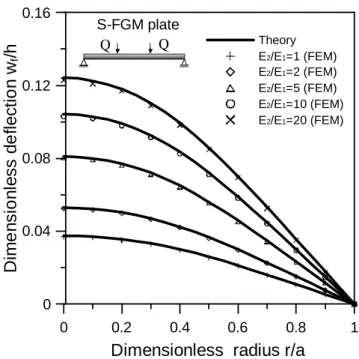
The formulation in Eq. (18) is the same as that in Reference [22]. Further to examine the correct of Eq. (17) and the effects of the steep of the material gradient on the mechanical behaviors, the variations of deflections wf along the radial direction are evaluated and
plotted forb=0.4a, ν =0.3, andE2/E1 =1, 2, 5, 10, 20 with fixed in E2 =2.1MPa. The results in Figure 2 are compared with the numerical solution obtained from the finite element program MARC.
4. Circular FGM Plates Subjected to Distributed Loads
4.1 Linearly distributed load
Consider a circular FGM plate with radius a thickness h subjected to linearly distributed load q r( )=q r a0 / , shown in Fig. 3(a). To obtain the solution of this problem, it
is assumed that a concentrated load q b0
Q db
= a acting at r=b. Then small deflection at r
(say point A) caused by the concentrated load q b0
Q db
= a is found. And the deflection at r is determined by superposing all effects of the distributed loads and it is:
3 2 5
0 5 11
5 (4 ) 3 (6 )
450 2 (1 ) (1 )
q a r a
aC r
w ν ν
ν ν
= − + + + ++ (19)
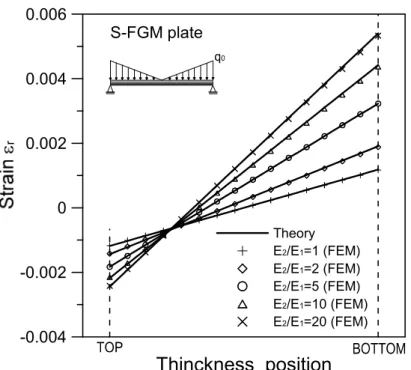
The formulae of the deflection in Eq. (19) is the same as that in Reference [23] for isotropic material. The distribution of strainεr and stress σrat r=a/ 5along the thickness direction for material index p=2andE2/E1=1, 2, 5, 10, 20with fixedE2 =2.1MPaare plotted in
Figures 4 and 5, revealing that the maximum stress of the FGM plates moves to the inner side of the plates rather than to the top or bottom surfaces of the circular FGM plates, which differs from a homogeneous plate.
4.2 Quadratic distributed load
Assume that the circular FGM plate shown in Fig. 3(b) is subjected to quadratic distributed load q r( )=q01 ( / )− r a 2. To evaluate the solution of this problem, first the
concentrated load Q in Eq. (24) is replaced by
2 2
0 2
a b
q db
a
− , and then with the manner
similar to the linearly distributed load in Section 4.1. The deflection of the circular FGM plate under quadratic load is found as:
( )
4 6 2
4 2 2
0 0 0
2
11 11 11
13 5
72 64 9 192 1
q a q r q a v
w r a r
C C a C v
+
= − + − + + − (20)
It is seen from Eq. (20) that the deflection
4 0
11
(31 7 ) 576(1 ) w q a
C ν ν
= +
+ at r=0 and w=0 at r=a.
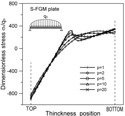
To study the effects of the material index pof FGM, the variations of stresses σrand σθ along the thickness direction for the material index p=1, 2, 5, 10, 20and E2 /E1 =5fixed are plotted in Figure 6, which depicts that the material index pdoes not obviously affect the stresses of FGM plates. The comparison of stresses σr, σθ along the radial direction are illustrated in Figure 10 for E2/E1 =5, 20, p=2. Figure 7 shows that the radial and tangential stresses are the same at center of the circular plate.
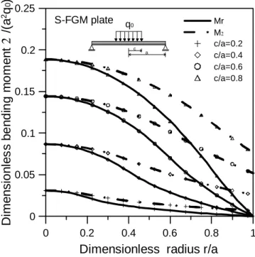
4.3 Partial uniform load
Consider a circular FGM plate shown in Fig. 3(c) subjected to partial uniform load with magnitude q0 in the range 0≤ ≤r c . The deflection at r (say point A) is
1 2 0
c r
f f
r
w=
∫
dw +∫
dw with q b a0 / replaced by q0 if point A is inside the range 0≤ ≤r c,and is 2
0 c
w=
∫
dwf if the point A is in the range c≤ ≤r a. After some manipulations, thedeflection for the circular FGM plate subjected to partial uniform load is
2 2 2 2 4
0 2
2
2 2
2 2
11
(1 ) (3 ) 8 (7 3 )
(2 ) ln
16q c c r2 (1 ) (1 ) r 4(1c ) 4r c for 0
w a r c
c a c
a r
C
ν ν ν
ν ν ν
− + +
= + − + + +
+ + +
+ ≤
≤
(21a)
( ) ( )
2 2
2 2 2 2
0
2 11
3 1
( ) ( ) 2 ln
16 1 2 1
q c v c v r
w a r r c
C v a v a
+ −
= − + − + + + for c≤ ≤r a (21b)
The maximum deflection wmax, located at the center of the circular plate, is found as:
2
2 2 2
0 max
11
3 7 3
4 4 ln
64 1 1
q c c
w a c c
C a
ν ν
ν ν
+ +
= + − + + (22)
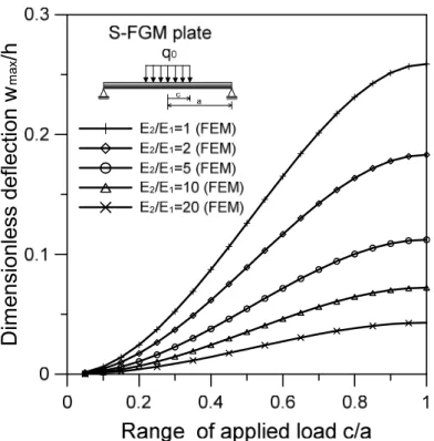
Figure 8 depicts the maximum deflection located at the center of the plate versus the ratio of /
c a for E2/E1=1, 2, 5, 10, 20 with E2 =2.1MPafixed. The maximum deflection in Eq.
(22) can be applied to homogeneous circular plate subjected to partial uniform load by setting
3 2
11 / [12(1 )]
C =Eh −ν in Eq. (34) and it reveals the same result with that in Ref 23 ].
When c=a, the circular FGM plate is subjected to uniform distributed load q in 0 the whole FGM plate, and Eq. (33a) is simplified as:
4 2 4
0
2 4
11
5 2 3
64 1 1
unifrom load
q a r r
w C a a
ν ν
ν ν
+ +
= + − + + (23)
Eq. (23) agrees with that in Ref. [23]. The deflection of a FGM circular plate subjected to concentrated load P at the center of the plate evaluated from Eq. (21b) by setting
0 / 2
q =P πcin Eq. (21b) and then takingc→0 is: