A PRELIMINARY STUDY OF IMAGE-BASED INDOOR NAVIGATION WITH
PANORAMIC CAMERA
Tsung-Che Huang a, Yi-Hsing Tseng b
Department of Geomatics, National Cheng Kung University, No.1, University Rd., Tainan City 70101, Taiwan; Tel:+886-62373876 ext.852 – a[email protected], b[email protected]
KEY WORDS: Indoor navigation, Image matching, RANSAC, Essential matrix, Spherical panorama image
ABSTRACT:
Image-based or vision-based navigation method is considered as the solution of in-indoor navigation. For example, an ego-motion estimation system with a single camera has been proposed and tested (Sih, 2014). The camera trajectory is estimated by using the information of matched image feature points between sequential images. Panorama images can be obtained by using a panoramic camera, which usually is a combination of several limited-field of view (FOV) cameras, such Ladybug. Such images cover almost all directions and have no limitation of FOV. A panoramic camera takes a numbers of images simultaneously and stitches them into a spherical panorama image (SPI) (Lin, 2014). In order to use panorama images for indoor navigation. It is necessary to investigate the moving pattern of the conjugate points in two panorama images taken at different positions or orientation. In this study, image features are extracted and matched, so that the moving vectors of the feature points can be plotted and studied on the images. Through observing the moving pattern of feature points, the relative positions and orientation between the camera stations may be solved. There are three test cases of tried in the experiments including camera movement, self-rotation and oblique. To extract and fine conjugate image features, we applied Speed-Up Robust Features (SURF) (Bay, 2008) for image feature matching and Random Sample Consensus (RANSAC) for error detection. Once the conjugate points are found, we can compute the essential matrix of the images and the relative orientation between images can be solved from the Essential matrix.
1. INTRODUCTION 1.1 Motivation
High accuracy navigation has been achieved since a successful integration of Global Navigation Satellite System (GNSS) and Inertial Measurement Unit (IMU). However, such navigation system are only available for outdoor open-sky environments. The navigation accuracy rapidly drops whenever GNSS signals are blocked. Although using alternative signals, such as Wi-Fi or radio signal, for positioning has been proposed, the complicated indoor environment leads to the bad result. Using the image-based or vision-based method to do the indoor navigation is an effective solution. Moreover, use the panorama image can get the more image information than use the frame image.
1.2 Overview
A preliminary test is conducted to investigate how the pattern of the vectors shows between two panorama images. The camera we used is Ladybug 5 and there are three different case in this experiment. Case I is straight movement of camera with distance 0.95m between two different sites. Case II is rotation of camera about 90˚ clockwise at a fixed site. Case III takes two images with camera kept horizontal and tilt about 10˚.
These images are processed by two methods. One used SURF algorithm to detect feature points and match conjugate points. Then RANSAC is applied to remove the wrong matching points. The other one manually choose the conjugate points which are evenly distributed in whole image.
To frame images, RANSAC provide the user high efficient computation and accuracy result. It is since that the projection type of frame image is affine transformation. If user take panorama image for image matching, RANSAC cannot perform well since the projection type of panorama image is spherical transform. This problem can be solved by changing the mapping model in RANSAC algorithm.
The geometric relations between two images Ik and Ik-1 of a calibrated camera are described by the so-called essential matrix. It contains the camera motion parameters up to an unknown scale factor for the translation. Essential matrix can be computed from 2D to 2D feature correspondences which has been done in the SURF and RANSAC. The main concept of 2D to 2D motion estimation is epipolar constraint.
1.3 Reference to related work
Motion estimation using a single camera is possible in related study. The results rely on intersection geometry. The lack of features in some circumstances may cause the navigation failure. To improve the quality of spatial data and obtain a solid solution for moving trajectory, applied panoramic camera is a suitable solution.
An image has the complete (360˚ horizontal by 180˚vertical denote 360 x 180) viewing coverage of the surrounding landscape is called spherical panorama image (SPI). There are a lot of multi-camera SPI sensors on the market. Ladybug is one of the famous SPI sensors, which is commonly applied to visual odometry in mobile mapping systems.
The minimal case solution of essential matrix involves five 2D to 2D feature correspondences using epipolar constraint. A
simple and straightforward solution for n ≧ 8 noncoplanar points is eight-point algorithm (Longuet-Higgins, 1981). With this methodologies, we can compute the essential matrix and do more application (Stewenius, 2006).
2. METHODOLOGY 2.1 SURF algorithm
SURF algorithm includes three parts which are feature detection, feature description and feature matching. In the detection part, Fast-Hessian matrix and integral image concept are applied to improve the efficiency of computation. SURF uses the determinant of the Hessian for selecting the scale and building the image pyramid to achieve scale-invariant property. Its feature descriptor is based on the sum of the Haar wavelet response around the points of interest. Once the descriptor is done, the descriptor of feature points between two images will be compared in Euclidian space and matching pair can be found.
2.2 RANSAC algorithm
There are lots of matching pairs after applying SURF algorithm, but some of these conjugate points are not correct matching. With RANSAC algorithm, the error matching can be detected and eliminated. The flowchart of RANSAC algorithm is shown as figure 1.
Figure 1. RANSAC computation flowchart
Firstly, the matching pair of the images will be chosen randomly, then the transform matrix between images is calculated. With the matrix, the conjugate points in one images can be transformed to another one. After all conjugate points are transformed, the threshold is set for testing whether the conjugate points are correct or not and record the number of correct matching pairs. This procedure will be executed many times till the user’s setting.
Finally, the case containing the most number of the correct matching pair is regard as the final matching result and the matrix in the case is also regard as the transformation matrix between two images.
To frame image, the transformation relation between two images is affine, so affine transform model in the RANSAC
algorithm is applied for computing. For SPI, it cannot work successfully anymore. That is because the relation between SPI is not affine but sphere. The most suitable solution is changing the model in the RANSAC algorithm. In this research, the essential matrix will be applied for the transformation model and keep enough and correct matching pair done by SURF. 2.3 Essential matrix
Essential matrix base on the coplanar condition, which means two perspective centroids and object point are on the same plane. So the hexahedral volume made up by the vectors is zero. With this constraint we can calculate the essential matrix. Essential matrix describes the relation between two images Ik and Ik-1 of a calibrated camera (Scaramuzza, 2012). It contains the camera motion parameters up to an unknown scale factor for the translation in the following form (Sabzevari, 2014):
k k k E t R (1) where
0
0
0
kt
z
t
y
t
t
z
t
x
t
y
t
x
The t matrix represents the translation between two images and it can be written as a skew-symmetric matrix. The definition for the essential matrix is
'T 0
p E p (2) In terms of the normalized image coordinates for corresponding points pp' are the conjugate points done by SURF and RANSAC algorithm. Essential matrix has only five degrees of freedom: both the rotation matrix R and translation t have three degrees of freedom, but there is an overall scale ambiguity, the essential matrix is a homogeneous quantity. The reduced number of degrees of freedom translates into extra constraints that are satisfied by an essential matrix. We investigate what these constraints are: a 3 by 3 matrix is an essential matrix if and only if two of its singular values are equal, and third is zero. Some method are proposed to derive the essential matrix and one of them is eight-algorithm. Each feature match gives a constraint of the following:
xx' xy' xz' x y' yy' yz' x z' y z' zz'
E0 (3)The symbols ( , , )x y z and ( ', ', ')x y z are the SPI coordinates. With the linear equation systemAE0, the parameters of E can be computed. This homogeneous equation system can be solved using singular value decomposition (SVD). The SVD of A has the form T
A A A
AU S V , and the least-squares estimate of E with ||E|| = 1 can be found as the last column of VA.
2.4 Extraction of camera from the essential matrix
The essential matrix may be computed directly from (3) using normalized image coordinates. Once the essential matrix is known, the camera matrix may be retrieved from E. A valid essential matrix after SVD is T
EUSV and had diag(S) = {1, Select the matching pair
randomly
Compute the transformation matrix of the images Transform the conjugate
points with transformation matrix
Record the number of matching pair suffice the threshold
1, 0}, which means that the first and second singular value are equal to one and the third one is zero. In order to compute the second camera matrix, C', we may assume that the first camera matrix is C
I| 0
(Nister, 2004). Both rotation and translation form E have two different solutions, so the C' has four different solutions. The four possible solutions are writtenas following: ' [ T| 3] CUWV u or C' [UWVT|u3] or C' [UW VT T|u3] ' [ T T| 3] CUW V u , where 3 (0, 0,1)T u t U .
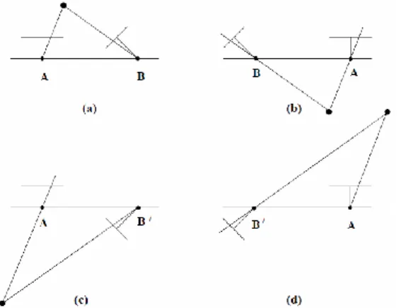
However, by triangulation of a single point X, the correct R, t pair can be identified. The four solutions are illustrated in figure 2, where it is shown that a reconstructed point X will be in front of both cameras in one of these four solutions only. Thus, testing with a single point to determine if it is in front of both cameras is sufficient to decide between the four different solutions for the camera matrix C' (Hartley, 2000).
Figure 2. The four possible solutions for calibrated reconstruction from E. Between the left and right sides there is a
baseline reversal. Between the top and bottom rows camera B rotates 180˚ about the baseline.
3. EXPERIMENT
This research first focuses on the geometry of image formation of a panoramic camera. The parameters of exterior orientation of an SPI will be defined according to the geometry of image formation. The experiment was done at the Department of Geomatics PRS Lab.
3.1 SPI sensors
In this study, the famous ladybug 5 was used to capture the panorama images. Ladybug 5 combines six fisheye cameras together. Each camera has about 0.5 mega pixels resolution and the whole ladybug 5 can achieve 3 mega pixels. Five of them capture the horizontal view and one of them captures the top view. With ladybug 5, it is easily to get the 360 x 150 SPI. Table 1 shows the specification of ladybug 5.
Ladybug 5 Properties
Image sensor model Sony 5 MP 2/3” Image sensor type 6 x Sony ICX655 CCD Maximum resolution 2048 x 2448 (each sensor)
Pixel size 3.45 μm
Lenses 6 x 4.4-mm focal length Field of view 90% of full sphere
Shutter Global shutter Table 1. Specification of ladybug 5
3.2 Experiment designed
There are three test cases of tried in the experiments. Case I is movement test, at first, take a panorama image at the one site then straight move the camera to next site. The distance between two different sites is 0.95m. Figure 3(a) shows the concept of the case I. Case II is rotation test, at first, take a panorama image at the one site then do not move the camera but rotate it. The rotational angle is 90˚ clockwise. Figure 3(b) shows the concept of cases II. Case III is oblique test, at first, keep the camera horizontal and take a panorama image then make the camera tilt about 10˚ and take another image. Figure 3(c) shows the concept of case III.
Figure 3(a). Top view of ladybug 5 in case I
Figure 3(b). Top view of ladybug 5 in case II
Figure 3(c). Side view of ladybug 5 in case III 3.3 Image property
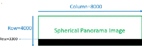
In the experiment, we set the SPI 8000 x 4000. Figure 4 shows the pixel coordinates of SPI projected onto a plane. Because there is no camera at the bottom of ladybug, it lead to the black area at the bottom of image. After acquiring the images, we used two different match methods to do the image matching. First one is automatically detect feature points and match conjugate points using SURF and RANSAC algorithm. The other one is manually detect the feature points in two panorama images then calculate the vectors.
Figure 4. The image coordinates of a SPI projected onto a plane
In automatically feature detect and match part, after using SURF to find feature points and match these points, we directly use RANSAC (affine model) for removing the error matching pair but get a bad result. So directly local matching (DLM) method is proposed to solve this problem. Though it seem to improve the result, it cannot increase the number of matching pair, which will lead to the bad geometry in orientation computation. The matching results are shown bellow.
4. RESULT AND DISCUSSION 4.1 Manual matching
4.1.1 Movement test: Figure 5(a) shows the result of manual matching. The yellow arrows represent the trajectory of camera and blue image is the first image while red image is the second image. All vectors gather and transpire from two stationary pints.
Figure 5(a). Manual matching with movement test
4.1.2 Rotation test: Unlike movement test, self-rotation of camera will not lead to the scene become bigger and smaller at different angle of image. All the objects moved in the horizontal, so the pattern of vectors are horizontal line. The result is shown as figure 5(b), where the yellow arrow represents the rotational direction of the camera.
Figure 5(b). Manual matching with rotation test
4.1.3 Oblique test: The tilt angle of the camera is about 10 ˚ . The pattern of the vectors is swirl and there are two points keep stationary on the image. Figure 5(c) shows the result, the red dot-line is the edge of the first image while the blue dot-line is the edge of the second image.
Figure 5(c). Manual matching with oblique test
4.2 SURF and RANSA (affine model)
Two images directly matched with SURF and RANSAC (affine model). The red image is the first image while blue image is the second image. In this case, RANSAC (affine model) will remove almost all match pair, which means there are few conjugate points on the image. Moreover these conjugate points are unevenly distributed around the image. Figure 6 shows the result of movement, rotation and oblique result in this method.
Figure 6(a). Movement test with RANSAC (affine)
Figure 6(c). Oblique test with RANSAC (affine)
4.3 Directly local matching (DLM)
To improve the bad matching result, we use local matching method for image matching, which means the images were divided into several sub-images then put it into the SURF and RANSAC (affine model). In this way, the number of conjugate points increase slightly. But it still has the unevenly distributed problem. Moreover, cross the image stitching line, there are no match pair. Figure 7 shows the result of three cases.
Figure 7(a). Movement result with DLM
Figure 7(b). Rotation result with DLM
Figure 7(c). Oblique result with DLM
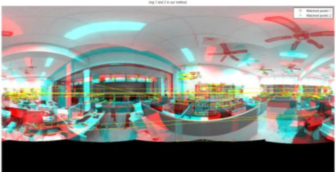
4.4 SURF and RANSAC (essential model)
Although DLM seems to improve the situation, the result still cannot be used in orientation computation. Because the projection type of the SPI is sphere, the affine model is not suitable for this case. The appropriate solution is find a suitable model for SPI. In this research, we changed the model from affine model to essential model and get the result shown as figure 7. Not only the number of matching pair increase
dramatically, but also a few of them are wrong matching. Figure 7(a). Movement test with RANSAC (essential)
Figure 7(b). Rotation test with RANSAC (essential)
Figure 7(c). Oblique test with RANSAC (essential)
4.5 Comparison of affine and essential model
Table 2 shows the comparison of affine and essential model in three different cases. Each case contains several images, five images in case I, four images in case II and three image in case III. The table record the number of total match pairs of SURF matching and percentage of retention points.
Table 2(a) shows the number of points in the case I is about 450 and after affine model was applied, the remainder points are about 130. If we change the model into essential, the remainder number can up to 360.
A1A2 A2A3 A3A4 A4A5
Affine 28% 31% 30% 38%
Essential 77% 81% 71% 82%
Total pts 404 413 466 500
Table 2(a). Comparison of affine and essential model in movement test
Table 2(b) shows the comparison in rotation test. Total points reach up to about 1900. That is because the rotation of camera contain the simplest change of view in these three cases, which
means SURF provide more match pair. Also the remainder points with affine model is about 760 while 1800 in essential model.
B1B2 B2B3 B3B4 B4B1
Affine 36% 34% 42% 41%
Essential 97% 96% 97% 95%
Total pts 1888 1836 1891 1870 Table 2(b). Comparison of affine and essential model in rotation
test
Table 2(c) shows comparison of oblique test. The number of total points is about 1200 with 5˚ difference. Because C1 and C3 differ 10 ˚ , the number of total points is fewer. Affine model provide about 360 points while essential prove about 1000 points.
C1C2 C2C3 C1C3
Affine 32% 38% 28%
Essential 93% 94% 73%
Total pts 1119 1384 760
Table 2(c). Comparison of affine and essential model in oblique test
5. CONCLUSION
In this study, we firstly focus on the pattern of the conjugate points between two SPIs. Therefore we designed three common cases of the camera orientation to test how the pattern will be in the panorama images. For frame images, the vectors of change view are easy to be analysed, since frame image contains few feature points, it make the image-based or vision-based become harder to accomplish. The panorama image contains almost full view that provide many feature points for navigation mission. If we want to apply the panorama image on navigation, the first step is to analyse the geometry of it. With the experiments, we can preliminary realize the change of the scene in SPI. Case I shows the movement of the panoramic camera lead to the scene become bigger and smaller. So the pattern is just like figure 5(a). Case II shows the rotation of the camera, the whole scene move with horizontal direction. So the pattern is horizontal line like figure 5(b). Case III shows the oblique of the camera. It make the pattern swirl toward two stationary points like figure 5(c). Every case in the experiment show that we cannot just put the panorama image into SURF and RANSAC (affine model), or the poor matching result will be given. The solution to this kind of problem is to find a suitable mapping model to replace the affine model in RANSAC. The results prove essential model can be used in the SPIs.
After get good matching pairs, the orientation computation can be implemented. Here, essential matrix again is applied to calculate the relative orientation of two SPIs. Essential matrix describe the relation between two calibrated cameras. The rotation and translation can be extracted from essential matrix once the essential matrix is computed. The way to derive essential matrix is SVD method. If the absolute orientation of one image is known and the relative orientation also known with essential matrix, the orientation of the other image can be derived successfully.
ACKNOWLEDGEMENTS
Thanks the support of MOST 104-2110-M-006-016 to this research.
REFERENCES
H. Bay, T. Tuytelaars, and L. Van Gool, 2008. SURF: Speeded up robust features, Computer Vision and Image Understading, 110(3), pp. 346-359.
R. Hartley and A. Zisserman, 2000. Multiple View Geometry in Computer Vision. Cambridge Univ., pp.257-260
Lin, K.Y., 2014. Bundle Adjustment of Multi-station Spherical Panorama Images with GPS Positioning. Master’s Thesis. Department of Geomatics. National Cheng Kung University. Longuet-Higgins, H., 1981. A computer algorithm for reconstructing a scene from two projections. Nature, 293(10), pp.133-135
D. Nister., 2004. An Efficient Solution to the Five-Point Relative Pose Problem. IEEE Transaction on Pattern Analysis and Machine Intelligence, 26(6), pp.758-759
D. Scaramuzza and F. Fraundorfer., 2012. Visual Odometry: Part I - The First 30 Years and Fundamentals. IEEE Robotics and Automation Magazine, 18(4), pp.85-87
H. Stewenius, C. Engels, D. Nister., 2006. Recent Developments on Directly Relative Orientation. ISPRS Journal of Photogrammetry and Remote Sensing, 60(4), pp. 284-294 R. Sabzevari and D. Scaramuzza., 2014. Monocular Simultaneous Multi-Body Motion Segmentation and Reconstruction from Perspective Views. IEEE International Conference on Robotics and Automation, pp.23-30
Sih, Y.R., 2014. Study on Vision-Based Navigation-Integration of Coplanarity and Collinearity Condition for Ego-Motion Estimation. Master’s Thesis. Department of Geomatics. National Cheng Kung University.