A General Design Method for Electric Machines Using Magnetic Circuit Model Considering the Flux Saturation Problem
You-Chiuan Hsu
Student Member, IEEE National Cheng Kung University
1 University Road 701 Tainan, Taiwan, R.O.C.
Min-Fu Hsieh
Member, IEEE
National Cheng Kung University 1 University Road 701 Tainan, Taiwan, R.O.C.
Richard A. McMahon
University of Cambridge 9 J.J. Thomson Avenue
Cambridge, UK [email protected]
Abstract - This paper proposes an analytical approach that is generalized for the design of various types of electric machines based on a physical magnetic circuit model. Conventional approaches have been used to predict the behavior of electric machines but have limitations in accurate flux saturation analysis and hence machine dimensioning at the initial design stage. In particular, magnetic saturation is generally ignored or compensated by correction factors in simplified models since it is difficult to determine the flux in each stator tooth for machines with any slot-pole combinations. In this paper, the flux produced by stator winding currents can be calculated accurately and rapidly for each stator tooth using the developed model, taking saturation into account. This aids machine dimensioning without the need for a computationally expensive finite element analysis (FEA). A 48-slot machine operated in induction and doubly-fed modes is used to demonstrate the proposed model. FEA is employed for verification.
Index Terms— magnetic analysis; magnetic circuits; doubly fed machines; induction machines, magnetic saturation.
I. INTRODUCTION
When designing an electrical machine, it is important to consider magnetic saturation as it will increase losses and limit machine performance. The equivalent magnetic circuit analysis (EMCA) has been widely applied to analysis and design of electric machines [1-5]. Most of the studies are based on the same concept mimicking the electrical circuit behavior. Due to excessive simplification, conventional EMCA often suffers problem of considerably low accuracy, and correction factors based on experiences are often employed for compensation. Therefore, it is commonly used for preliminary design, and confirmation or modification using other approaches (e.g., finite element analysis) is required.
For doubly-fed machines (DFMs) excited by two independent sources applied to separate windings, common EMCA may not be capable of handling such complex flux patterns. In a previous study [1], the EMCA method has been applied to modeling of doubly-fed doubly-salient machines.
However, the model was limited to particular slot-pole configuration and was insufficiently general for machine design despite the saturation was considered. For other commonly used equivalent circuit models for analysis of induction machines or doubly-fed machines, the flux
saturation problem is not considered [6]. As an alternative, finite element analysis (FEA) can be used to directly analyze the flux patterns but the entire process can be computationally expensive. In addition, changing the design parameters (dimensions, slot number, winding arrangement) in FEA will often require the model to be reconstructed, which would be extremely time-consuming.
Therefore, this paper develops a generalized, accurate and time-effective EMCA method for design and analysis of various electric machines, taking flux saturation into account.
Unlike conventional EMCA, the proposed model employs a completely circular configuration that physically joints all the magnetic loops on all the stator teeth to enhance the accuracy by considering machine geometry. This will be able to calculate the flux patterns for any machine slot-pole combinations with any windings. In this model, the magnetomotive forces (MMFs) produced by the windings are calculated to determine the material permeability (operating point) according to the hysteresis loop so that the flux can be accurately obtained. This calculation is performed simultaneously for all the MMF sources instead of applying superposition, and consequently the locations where magnetic saturation occurs can be predicted. An accurate solution can thus be rapidly provided for design of any types of electric machines, including doubly-fed machines (DFMs), which possess inherent complex flux patterns that vary with two current phases, rotor position and load, etc. This would be difficult to achieve with the lengthy FEA simulation, which however, is used to verify the accuracy of the model.
II. MACHINE MODELING
A. Geometry Matrix
In this paper, all of the components in the magnetic circuit are modeled in accordance with machine configuration and material characteristics. The definitions of the parameters are given in Fig. 1 for the geometry of a general electric machine.
Other related parameters include the vacuum permeability µ0, stack length Lst, number of slots Ns and iron relative permeability µiron. Four assumptions are given prior to development of the proposed model: (a) the permeability of the iron core is variable, as expressed using the variable reluctances shown in Fig. 2; (b) the flux flowing through one
stator tooth flows through the air gap uniformly within a slot pitch; (c) the rotor is treated as slotless, and (d) all the flux is strictly constrained in the magnetic circuits (note that the flux leakage has been considered in the model, as the paths having the reluctance Rl shown in Fig. 2).
The important components in the magnetic circuit are defined in Fig. 2, including the air-gap magnetic reluctance Rg, the reluctance of any tooth Rt, the rotor yoke (segmented into the number of slots) reluctance Rr and the stator yoke reluctance. These magnetic components are further defined using the following equations:
Rg =g·Ns/2π·µ0·rro·Lst (1)
Rt (µiron)=(Rro-g-rro)/µ0·µiron·Wt·Lst (2) Rr (µiron)=2π·(rro-Wyoke_r/2)/Ns·µ0·µiron·Wyoke_r·Lst (3)
_ 0 _
( ) 2 ( 2)
s iron ro yoke s s iron yoke s st
R µ = π⋅ R +W N ⋅µ ⋅ ⋅µ W ⋅L (4) The current in one slot can be replaced by an MMF source.
All these magnetic components used in the magnetic circuit model are shown in Fig. 2, where Fsn represents the MMF in the n-th slot. Note that the reluctancs in (2)-(4) are numbered (e.g., Rs1, Rs2 to RsNs) by the segments shown in Fig. 2
Wt
g
Stator Wyoke s_
Rotor Wyoke r_
r
roRro
Wshoe
Fig. 1. Definitions for geometry of general electric machines
GND
O N
Rg 1
Rt 1
Rs
1
Rr
Rl 2
Rt
Rg
Rl Rl
sNs
R
2
Rs
rNs
R
2
Rr
1
Fs
sNs
F
2
Fs
GND
O N
Rg 1
Rt 1
Rs
1
Rr
Rl 2
Rt
Rg
Rl Rl
sNs
R
2
Rs
rNs
R
2
Rr
1
Fs
sNs
F
2
Fs
Fig. 2. Machine modeling: definitions for magnetic components
Any Ns slot machine can be modeled as a regular arrangement. The equivalent magnetic circuit for a machine can be determined once the number of slots Ns is determined and can then be solved by the nodal analysis algorithms using a computer program. The details of the model are given in the following derivation. First, all of the parameters discussed
above based on the machine geometry, materials and winding layouts are arranged in matrix A given below:
G B A C D
=
(5)
where G is a (4Ns-1)
×
(4Ns-1) matrix consisting of sixteen sub-matrices (matrices B, C and D will be explained later) that are arranged as:1 2 3 4
5 6 7 8
9 10 11 12
13 14 15 16 ( 4Ns 1) (4Ns 1)
G G G G
G G G G
G G G G G
G G G G − × −
=
(6)
The details of the sub-matrices (G1–G16) contained in matrix G are given in the following series of equations, where all the parameters can be obtained from (1) to (4). It is noted that these matrices have different sizes, and the combination of them will form the (4Ns-1)
×
(4Ns-1) matrix G.1
1 2
1 0 0
0 1
0
0 0 1
s s s
s
s
sN N N
R G R
R ×
=
K
M
M O
K
(7)
1
2 2
( 1) ( 1 )
1 0 0
0 1
0 1
0 0
s
s s
s
s
s N
N N
R
R G
R −
× −
−
−
=
−
K
M
M O
K
(8)
[ ]
3 0
s s
N N
G = × (9)
[ ]
4 0
s s
N N
G = × (10)
1
5 2
( 1) ( 1)
1 0 0
0 1
0 0 1 0
s s s
s
s
s N N N
R
G R
R −
− ×
−
−
=
−
K
M
M O
K
(11)
1 2
2 3
6
( 1) ( 1) ( 1)
1 1
0 0
1 1
0
0
1 1
0 0
s s
s s
s t
s t
s N tN N N
R R
R R G
R − R
− × −
+
+
=
+
K
M
M O
K
(12)
2
7 3
( 1)
0 1 0
0 1
0 0 1
s s s
t
t
tN N N
R G R
R − ×
−
−
=
−
K
M
M O
K
(13)
[ ]
8 0( 1)
s s
N N
G = − × (14)
[ ]
9 0
s s
N N
G = × (15)
2
10
3
( 1)
0 0
1
1
0
0 0 1
s s s
t
t
tN N N
R
G R
R × −
−
−
=
−
K
M
M
O K
(16)
1
2
11
1 1 2 1 1
0 0
1 1 1 2
0 0
0 0 1
1 1 1 1 2
0 0
s s s
g t l l l
l g t l
l
l l g tN l N N
R R R R R
R R R R
G
R
R R R R R
×
− −
+ +
− + +
=
−
− −
+ +
K
O
O O M
M O O
O
K
(17)
12
1 0 0
0 1
0
0 0 1
s s
g
g
g N N
R
G R
R ×
−
−
=
−
K
M
M O
K
(18)
13 9
G =G (19)
[ ]
14 0 ( 1 )
s s
N N
G = × − (20)
15 12
G =G (21)
5 1 1
1 1 2 2
2 16
( 2)
( 2) ( 1)
( 1) ( 1)
1 1 1 1 1
0 0
1 1 1 1 1
0 0 1
1 0
1 2 1 1
0
1 1 1 1 1
0 0
s
s
s s
s s s s s s
g r r r rN
r g r r r
r
r N
r N r g r N
rN r N rN r N g N N
R R R R R
R R R R R
G R
R
R R R R
R R R R R
−
− −
− − ×
− −
+ +
− + + −
−
= −
− −
+
− −
+ +
K
O O M
M O
K
(22)
Matrix B in (5) is in the form of Boolean functions whose signs are determined by the directions of the MMF sources due to winding currents. For general case, matrix B can be expressed by (23) to (26). Matrix C is a reverse matrix of B while matrix D is a zero matrix.
[
1 2 3 (4]
s 1) sT
N N
B= B B B − × (23)
where
[ ]
1 1
s s
N N
B =diag × (24)
2
( 1)
0 1 0
0
0 1
s s
N N
B
− ×
−
=
−
L
M O M
L
(25)
[ ]
3 02
s s
N N
B = × (26)
C=BT (27)
[ ]
0D= (28)
To construct the analytical model, the relationship between MMF sources and flux produced needs to determine.
Matrix x is hence introduced, which is given as:
(5Ns 1) 1
x F
φ − ×
=
(29)
where F indicates the absolute MMF at the nodes of the circuit model, as defined in Fig. 3, and ϕ represents the flux produced due to F. The MMF F and flux ϕ are respectively given by:
1 2 (4 1) (4 1) 1 T
Ns Ns
F F F F −
− ×
= L (30)
[
1 2]
1T Ns Ns
φ φ φ= L φ × (31)
F0
O O N
N
s 1
FN−
F2
Ns
F
s 2
FN+
F1
2Ns 1
F −
2Ns
F
s 1
FN+
2Ns 1
F +
2Ns 2
F +
N I⋅ 1
Fig. 3. the generalized arrangement
The magnitude of the MMF produced by external current sources can be defined with matrix z as given by:
[
1 2 (5]
1) 1 Tz= Z Z Ns− × (32)
where
[ ]
1 0( 4Ns1) 1
Z = − × (33)
2 1 2 s 1
T
s s sN Ns
Z F F F
×
= L (34)
where Fsn is the MMF in the n-th slot. The MMFs are numbered simply because they are solved simultaneously instead of using superposition.
Finally, matrix x can be easily obtained by the following equation, where the flux density of the primary components can be indirectly obtained.
x=A z−1 (35)
The flux flowing through the n-th tooth can be expressed as
( )
, 1, 2, , 1,
s
s s
tn n n N tn s
tN N tn s
F F R n N
F R n N
φ φ
= − + = −
= − =
L (36)
Moreover, the flux flowing through the n-th air-gap can be given by
2
2
, 1, 2, , 1
,
s s
s s
N n n N
gn s
g
N N
gn s
g
F F
n N
R
F F
n N R
φ φ
+ − +
= = −
−
= =
L
(37)
In this form, the model is a function of Ns, and this will make the developed model a general approach applied to
different numbers of slots. Therefore, it is not necessary to rebuild the magnetic circuit for each particular case. The flux between any two nodes can be obtained with the MMFs at the nodes and the reluctances in between. Thus, the entire flux patterns can be determined.
B. Saturation Estimation Strategies
In order to observe the saturation level in each magnetic component of the model, an iterative algorithm is employed.
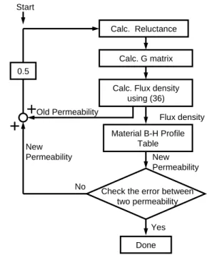
A relative permeability versus flux density profile representing the material characteristics for the stator and rotor is tabulated in the iterative process to update the permeability during the calculation. The permeability is first assigned an indiscriminate value that can be out of the material profile for initiating the process. It will soon converge to the material profile after several iterations as the external current sources and geometric dimensions are determined. Fig. 4 shows the process of the iterations. In this step, the flux density is governed by matrix G and the external current sources. It is noted that during the calculation, the teeth and other major magnetic components can have different flux density and thus every of them will go through the process shown in Fig. 4 until convergence.
Calc. Reluctance
Calc. G matrix
Done
Check the error between two permeability
Flux density 0.5
Material B-H Profile Table Old Permeability
Start
Yes No
New Permeability New
Permeability
Calc. Flux density using (36)
Fig. 4. The iteration process of permeability estimations
To observe the convergence of the iteration process to the hysteresis loop, Fig. 5 presents a track of converging operating points for one tooth of a 48-slot machine for demonstration. Initially, a random permeability is assigned (1st Round in Fig. 5) and as can be seen it is away from the hysteresis loop. After 15 iterations, the operating point gradually moves onto the curve as shown in Fig. 5. Hence, this demonstrates that the process can update the material permeability and thus obtain the accurate flux density in accordance with the MMFs applied.
85 90 95 100 105 110 115 120 125 130 0.55
0.6 0.65 0.7 0.75
Magnetic Intensity(A/m)
Flux Density (T)
Flux Density at Tooth No.4
Hysteresis loop
1stRound
15thRound 2ndRound
3rdRound
Fig. 5. The track of the operating point in the fourth stator tooth on a 48 slot doubly-fed machine which is detailed in the following section.
III. FINITE ELEMENT VERIFICATION
This section focuses on verification of the developed magnetic circuits and saturation estimation strategy using FEA. A 48-slot machine excited with 10 Amp-turn in the 1st slot (only one slot) is shown in Fig. 6, where the flux pattern is presented and the flux density on each tooth can be calculated. The dimensions of the investigated machine are given in Table 1. The capability of this model to update the permeability due to excitations has been demonstrated in the previous section. At this stage, the accuracy of the magnetic circuit model is solely verified based on a constant permeability without considering the saturation effect for simplicity. The flux on each tooth is compared between the simulation and the developed model, as shown in Fig. 7. It can be seen that both cases agree well. Therefore, the accuracy of the analytical model is validated.
Source
Air gap 1thtooth 48thslot
1thslot
48thtooth
Fig. 6. FEA study: flux pattern of FEA with 10 Amp-turn applied at the first slot
-0.15 -0.10 -0.05 0.00 0.05 0.10 0.15
0 2 4 6 8 10 12 14 16 18 20 22 24 26 28 30 32 34 36 38 40 42 44 46 48 Tooth Number
Flux Density (Tesla)
Magnetic Model FEA Simulation
Fig. 7. Flux comparison in each tooth (under constant relative permeability of 4000).
Having verified the developed model, the variable permeability estimating process discussed above is included to enable a more accurate model to be constructed. The 48- slot machine with single winding is first studied. A dc current of 5 A is applied to the 4-pole 3-phase windings in wye connection with 18 turns for each coil. The layouts of the winding can be referred to [2] and the details are given in Table 2 (stator winding 1). For the analytical model, the hysteresis loop of the iron core material [7] is constructed in the MATLAB program. The flux density distributions on all the 48 teeth obtained from magnetic model and FEA are compared in Fig. 8, where the 4-pole pattern can be observed and both cases agree well. However, with the current applied to the single windings, the material has not been operated into the saturation region.
Therefore, to investigate into the saturation effect, the 48- slot machine operated in the doubly-fed mode is studied with the two set of windings whose details are given in Table 2.
This time, the 5 A dc current is fed to both windings. As shown in Fig. 9, the flux density with and without considering the saturation is compared using the developed model. It can be seen that the flux pattern is irregular under the actions of both windings, and the saturation effect can be observed at around the 1st tooth and 24th tooth locally.
Apparently, in Fig. 9, the constant permeability case is not capable of reflecting the saturation effect and results in overestimation of local flux. From the above discussion, the saturation condition of the components in the magnetic circuits can be monitored. As shown in Fig. 10, the permeability on different machine teeth (black dots) is predicted (every point is the result from the process in Fig. 4).
From Fig. 10, the material B-H profile indicates that two operating points appear to saturate the machine (the saturation flux density is around 1.5 T for the material used).
These two operating points also represent the stator teeth whose flux density is into the saturation region. The result indicates that the machine design may need to be modified to prevent from saturation.
From the above discussion, the accuracy, generalization and effectiveness can be verified.
-0.50 -0.40 -0.30 -0.20 -0.10 0.00 0.10 0.20 0.30 0.40 0.50
0 2 4 6 8 10 12 14 16 18 20 22 24 26 28 30 32 34 36 38 40 42 44 46 48 Tooth Number
Flux Density (Tesla)
Magnetic Model FEA Simulation
Fig. 8. The flux density distribution in stator teeth, with 2.5A going into two phases and 5A going out from the other phase.
-2.50 -2.00 -1.50 -1.00 -0.50 0.00 0.50 1.00 1.50
0 2 4 6 8 10 12 14 16 18 20 22 24 26 28 30 32 34 36 38 40 42 44 46 48 Tooth Number
Flux Density (Tesla)
Variable Permeability Constant Permeability
Fig. 9. The flux density distribution in the stator teeth with doubly winding excited.
0 1000 2000 3000 4000 5000 6000
0 0.2 0.4 0.6 0.8 1 1.2 1.4 1.6 1.8 2
Magnetic Intensity
Flux Density (T)
Teeth Flux Density Track
Fig. 10. The operating points (black dots) on the hysteresis loop for the 48 teeth. One dot may represent multiple teeth because they are under the same operating conditions. This also shows that all of spots are converged into the material profile.
IV. CONCLUSIONS
An analytical model based on magnetic circuits has been proposed for design and analysis of general electric machines.
An iteration technique to obtain accurate permeability affected by external sources has also been developed to work with the model. The accuracy of the proposed model has been verified by FEA on a 48-slot machine in both the induction and doubly-fed modes. The capability to obtain the entire machine flux patterns by simultaneously taking all the winding MMFs
into account has been demonstrated. Moreover, the saturation region has also been predicted for the investigated machine, where the operating points (material permeability) can be monitored. Therefore, the developed model is sufficiently accurate to be applied in the design of various electric machines without the aid of time-consuming finite element analysis.
TABLEI MAIN MACHINE DIMENSIONS
Appearance Symbol
Description Value Unit
lg Length of the air gap 0.65 mm
NS Slot number 48
Lst Stack length 1000 mm
Wt Width of the tooth 8.64 mm
_ yoke r
W Width of the rotor yoke 20 mm
0
rr Rotor radius 90.35 mm
Rro Outer slot radius 117.55 mm
Wshoe Width of the slot shoe 2 mm
TABLEII STATOR WINDING LAYOUT
Stator winding 1 Pole 4
Coil per phase
16 (connected in series)
Turns per coil 18
Stator winding 2 Pole 8
Coil per phase
16 (connected in series)
Turns per coil 18
ACKNOWLEDGMENT
This work is in part supported by National Cheng Kung University and the National Science Council of Taiwan under contract 97-2221-E-006-268-MY2.
REFERENCES
[1] K.T. Chau, M. Cheng and C.C. Chan, “Nonlinear magnetic circuit analysis for a novel stator doubly fed doubly salient machine”, IEEE Trans. Magn., vol. 38, no. 5, 2002.
[2] P. Campbell, “The magnetic circuit of an axial field D.C. electrical machine,” IEEE Trans. Magn., vol. 11, no. 5, 1975.
[3] J.D. Law, T.J. Busch, and T.A. Lipo, “Magnetic circuit Modeling of the field regulated reluctance machine Part I: model development,”
IEEE Trans. Energy Conversion, vol. 11, no. 1, 1996.
[4] H. Polinder, J.G. Slootweg, M.J. Hoeijmakers and J.C. Compter,
“ Modeling of a linear PM machine including magnetic saturation and end effects: Maximum force-to-current ratio,” IEEE Trans. Industry Applications, vol.39, no. 6, 2003.
[5] V. Litovski and M. Zwolinski, VLSI Circuit Simulation and Optimization, Kluwer Academic Publishers, 1997.
[6] P.C. Roberts, R.A. McMahon, P.J. Tavner, J.M. Maciejowski and T.J.
Flack, “An equivalent circuit for the brushless doubly fed machine (BDFM) including parameter estimation and experimental verification,” IEE Proceedings: Electric Power Applications, vol.
152(4), pp. 933 – 942, 2005.
[7] Iron core model: CSC35CS550 supplying by ChinaSteel. Corp.