行政院國家科學委員會補助專題研究計畫 成 果 報 告
□期中進度報告
拇指在施行後前向滑動治療技術時關節受力狀況之生物力學分析 (2/2)
計畫類別:
個別型計畫 □ 整合型計畫計畫編號:NSC - - - - -
執行期間: 94 年 8 月 1 日至 95 年 10 月 31 日
計畫主持人:徐阿田
共同主持人:張冠諒、蘇芳慶、張志涵、官大紳 計畫參與人員: 林世偉、張茹茵
成果報告類型(依經費核定清單規定繳交):□精簡報告
完整報告本成果報告包括以下應繳交之附件:
□赴國外出差或研習心得報告一份
□赴大陸地區出差或研習心得報告一份
□出席國際學術會議心得報告及發表之論文各一份
□國際合作研究計畫國外研究報告書一份
處理方式:除產學合作研究計畫、提升產業技術及人才培育研究計畫、列 管計畫及下列情形者外,得立即公開查詢
□涉及專利或其他智慧財產權,□一年
二年後可公開查詢執行單位:國立成功大學物理治療學系
中 華 民 國 96 年 4 月 10 日
摘要
物理治療師容易有拇指相關之疼痛、損傷、功能限制、或失能,尤其是常使用徒手治療技術 之骨科物理治療師尤其常見。本研究之目的為利用新鮮屍體上肢樣本進行拇指前後滑動操作 技術之實驗模擬。最終之目的為探討拇指尖力量、肌肉力量與拇指關節運動學間之互動關連。
本研究使用四個急凍之新鮮屍體前臂與手部之樣本,經適當解剖處理後架設於一特製配備有 一伺服馬達與一六軸分力儀之實驗儀上,八條與拇指運動相關肌肉之力量則以標準法碼經滑 輪系統連接施加於肌肉之末端肌腱來替代。六軸分力儀用於記錄拇指端之力量。拇指關節角 度則以數位相機攝影量測。實驗結果發現實驗時拇指關節之初始角度對後續拇指關節之運動 學與穩定度有決定性之影響。拇指指端使力時其關節運動學互動通常以與其最鄰近關節相反 方向進行。拇指指間關節伸直時其掌指關節因反應力矩而趨於屈曲,而腕掌關節則趨於伸直。
而拇指指端使力增加時增減肌肉力量似乎並無法明顯改變拇指關節之角度運動學表現。未來 研究應修改實驗儀器設計以增加拇指指端使力之大小,另外亦應確定性別與柔軟度對拇指指 端所能產生力量大小的影響以及其與拇指基部關節關節炎與疼痛之關連。
關鍵字: 拇指,拇指指端力量,關節鬆動術、關節操作術、實驗模擬
Abstract
As a professional, physical therapists are prone to thumb injuries, especially those who with extensive manual technique as part of their daily menu of therapeutic activities in clinics. They are at risk of pain, impairments, functional limitations and disabilities involving their thumbs. The purpose of this study was to use an anatomical model of the thumb by the experimentally simulated the unilateral P-A glide manipulation technique. The ultimate goal was to investigate the interaction among kinematics of the thumb joints, the thumb-tip force and the muscle activity.
4 cadaver hand and forearm specimens were procured for this study. A test frame equipped with a servomotor and a 6 axis load cell was designed and manufactured to serve as the platform for the experiment. The specimen was rigidly fixed to the test frame with its tip of the thumb pointing toward the top plate of the 6 axis load cell. Weights and pulleys properly located at the test frame redirected the cable connecting to the tendon-aponeurosis complex. The 6-axis load cell was employed to register the force on the tip of the thumb when it was being driven by a servo motor toward the thumb until designated force levels. A total of 8 muscles acting on the thumb and 6 loading conditions with varying proportions of muscle loads were applied.
Based on the results of the present study we documented that the initial joint angles significantly influenced the behavior of thumb joints during thumb-tip loading. The thumb joint usually compensates for the adjacent joint position by reciprocal flexion or extension due to reactive torque created at the opposite ends of the intervening bone. As the thumb-tip load increased, changes in muscle loading patterns resulted in no obvious changes in joint kinematics. Further research works include the modification of the testing apparatus to extend the testing range of the thumb-tip load were necessary. It is also necessary to ascertain the influence of gender and flexibility on thumb tip force generation and their association with the osteoarthritis or pain in the joints of the thumb.
Key Words: Thumb, Thumb tip force, Mobilization, Manipulation, Experimental simulation
Table of Contents
報告封面 ………1
中文摘要 ………2
Summary ………. 3
Introduction ……… .5
Literature Review……… .6
Purposes of the Study ……….. 7
Materials and Methods………...8
Results ……… 13
Discussion ………21
Conclusion ………22
References ……….23
Introduction
Thumb biomechanics
For physical therapy professionals the values of the hands and thumb can never be over emphasized, especially after 1980s when the development of the physical therapy profession world wide, influenced primarily by physiotherapists in Australia and New Zealand, entered the so called
‘JointEra’and itprevailstilltoday [1].Themain themeofthe‘JointEra’constitutesaconceptual emphasis on the restricted arthrokinematics as the main source of joint related pain and dysfunction.
Under this conceptual framework, orthopedic physical therapy examinations emphasize on manual assessmentofjoint“play”(accessory motions), identifying soft tissue and joint restrictions, evoking or noting associated pain responses, and on the mechanical causes of injury. The treatment strategy is thus directed naturally towards the elimination of these soft tissue and joint restrictions and the restoration of normal arthrokinematics [1]. Among various treatment techniques and procedures employed, manual therapy, joint mobilization and manipulation become the most popular choice among available procedures by orthopedic physical therapists. These techniques (manual therapy, mobilization and manipulation) involve extensive (and in numerous instances strenuous) uses of the handsand thumbsasisimplied in theterm ‘manual’therapy. In the practice of manual therapy, many joint assessment, mobilization and manipulative procedures involve application of pressure through the tip or pulp of the thumb to impart passive movements to the target joint being treated [2]. Such procedures may impose a significant amount of stress to the interphalangeal (IP), metacarpophalangeal (MCP) and carpometacarpal (CMC) joints of the thumb and result in pain in these joints. Pain at the MCP joint was most likely to be caused by joint laxity or hypermobility which allowed hyperextension at this joint under load, causing reciprocal flexion and adduction of the first metacarpal and dorsal subluxation at its base. Potential sources of pain of manipulative physical therapists at the MCP joint of the thumb include the proper and accessory collateral ligaments, the volar plate, the joint capsule, or the muscular structure [3]. Hypermobility at the MCP joint is believed to be related to the development of osteoarthritis and pain at the MCP and the CMC joints and in the latter case by concentrating forces at its palmar aspect of the joint [2-6].
Asthe‘JointEra’entersitsthird decade,many orthopedic ormanualphysicaltherapists,who have employed manual therapy as the primary form of their clinical practice throughout their professional lives, and who were frequently involved in treating patients with work related musculoskeletal disorders, are now themselves suffered or at risk for the same pain, impairments, functional limitations and disabilities involving the most valuable assets of their trade - their own hands and thumbs [7-10].
Literature Review
Prevalence of Thumb Pain in Physical Therapists
Bork et al [7] surveyed 1160 physical therapists and reported their results in the journal
‘Physical Therapy’ in 1996. In this report the authors found that the wrist and hand problems constituted 29.6% of work related musculoskeletal disorders, second only to that of the lower back disorders which constituted 45% of the total number of disability. The authors also noted that physical therapists who performed manual therapy routinely were 3.5 times more likely to suffer musculoskeletal symptoms than their colleagues in other physical therapy specialties [7]. Along the same line, Cromie et al [8] reported an increased risk of pain in the thumbs in manual physical therapists, with 33.6% of their 536 respondents complaining of thumb pain lasting more than three days, with a severity score on a visual analogue scale of 3/10 or greater. West and Gardner [9] also reported that a high proportion (82%) of their respondents complained of an aggravation of pain when performing manual therapy techniques. A survey of the titled members of Musculoskeletal Physiotherapy Australia who either have completed postgraduate education in Bork et al [7]
surveyed 1160 physical therapists and reportedtheirresultsin thejournal‘PhysicalTherapy’in 1996. In this report the authors found that the wrist and hand problems constituted 29.6% of work related musculoskeletal disorders, second only to that of the lower back disorders which constituted 45% of the total number of disability. The authors also noted that physical therapists who performed manual therapy routinely were 3.5 times more likely to suffer musculoskeletal symptoms than their colleagues in other physical therapy specialties [7]. Along the same line, Cromie et al [8] reported an increased risk of pain in the thumbs in manual physical therapists, with 33.6% of their 536 respondents complaining of thumb pain lasting more than three days, with a severity score on a visual analogue scale of 3/10 or greater. West and Gardner [9] also reported that a high proportion (82%) of their respondents complained of an aggravation of pain when performing manual therapy techniques. A survey of the titled members of Musculoskeletal Physiotherapy Australia who either have completed postgraduate education in
Common strategies adopted by these therapists to reduce pain included changing or modifying their treatment techniques employed, using splints or taping during mobilization and/or manipulation [11-12], or seeking physical therapy or medical treatment [8-9]. No report, however, was available on what types of mobilization techniques were adopted by these therapists with thumb pain when treating their patients.
Kinematics literature of PA Glide
A thorough analysis of the biomechanical situations occurred in the thumb during these high risk procedures such as unilateral and central P-A glide techniques and their less strenuous alternatives would be a first step towards helping physical therapists in preventing such job related pains and disabilities. Such endeavor requires the employment of a realistic biomechanical model of the thumb. However, there is a lack of realistic biomechanical model of the thumb because of the
variability/ uncertainty of musculoskeletal parameters [13], varied kinematic descriptions [12-17]
and solution for the muscle redundancy problem [13], and the paucity of data available to validate the model with in vivo muscle coordination (activation) pattern and force output [18]. In a recent study, Valero-Cuevas et al [19] concluded that the choice of kinematic description of the thumb was more critical than the solution method or the variability/uncertainty of musculoskeletal parameters.
Advances in motion analysis technology, however, have made possible the use of surface markers and video based motion analysis system for measuring the motion of the thumb [20-21] and allowed the kinematic description of the thumb (axes of motion) to be realistically derived from motion analysis of the thumb in vivo as well as in vitro with techniques developed for the elbow and hip [22-23]. The muscle coordination or activation pattern could be obtained by the use of wire EMG techniques [24-25]. The present proposal is an initial step towards the construction of a more realistic model of the thumb and will use the unilateral P-A glide manipulation as the model task.
Purposes of the Study
After the conclusion of an extensive literature review, it is clear that, as a profession, physical therapists are prone to thumb injuries especially when extensive manual techniques are involved as part of their daily menu of therapeutic activities in the clinics. Furthermore, no study had ever reported the biomechanics of the thumb while physical therapy techniques or similar tasks were simulated by a mechanics frame and cadaver.
Therefore, the purpose of this study was to use an anatomical model of the thumb by the experimentally derived stress distribution patterns of the metacarpophalangeal joint during a simulated unilateral P-A glide manipulation techniques. The ultimate goal was to seek the behavior of thumb posture between the tip force of thumb and the muscle stress.
Materials and Methods
Four cadaver hand and forearm specimens from three males and one female were used in this study. A biomechanical testing system was designed and manufactured to simulate forces acting on the tip of thumb, and providing pull on the muscles to maintain the posture during the simulated the unilateral P-A glide techniques.
Specimens
Four fresh frozen cadaveric hand and forearm specimens prepared by disarticulation at the middle position of the forearm will be procured and used for the present study. All specimens will be stored at –20℃ until the day before testing. A radiograph (anteroposterior [AP] view) of each specimen was taken and inspected so that specimens with gross abnormalities detectable by the radiographs could be eliminated from the study.
Preparation of Specimens
The specimens were thawed overnight at room temperature in preparation for dissection and testing. All soft tissues approximately 5 cm proximal to one fourth of the forearm from wrist were removed. We identified the plane formed by ulna and radius defined as the front plane.
After removal of the skin and subcutaneous tissues over forearm, thenar eminence, web space and the dorsum of the proximal thumb, the belly of each muscle involved in the control of the thumb was carefully dissected and special care was taken to preserve tendons and aponeuroses (fascial planes where muscle fibers insert before joining the tendon). The proximal ends of the ulna and the radius were then potted together in a rectangular mold (30×60×60 mm) with
liquid resin (Red Mount 911, Yu-De Industry, Tainan, Taiwan) mixed in equal percentages by weight.Tendons of all eight muscles controlling the thumb motion, including extensor pollicis longus (EPL), extensor pollicis brevis (EPB), abductor pollicis brevis (APB), flexor pollicis longus (FPL), flexor pollicis brevis (FPB), adductor pollicis (AP), Abductor pollicis longus (APL) and Opponens pollicis (OPP), were identified. The
surgical suture
technique reported byKrackow et al [26] was used for securing the end of the distal tendon and, at the other end, connected to a high-strength nylon thread. A screw with small ring rigidly fixed on the bony attachment of the proximal tendon of each muscle acted as the pulley to re-direct the nylon thread in the direction of pull of the muscle mimicking the action of the muscle when pull upon.
Instrument Design and Development
Instrumentation
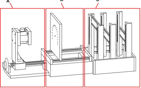
The test frame (Figure 2.1) was custom-manufactured to serve as the platform for the experiment. There are three subunits in this test frame: a force controlled unit (A), a
clamping-guiding unit (B), and a weight and pulley unit (C). The force controlled unit consisted of a servo motor, a ball screw, and a 6-axis force sensor. A servo motor (SINANO, model 6CC401G) coupled with a ball screw (pitch is 5mm) to provide the motive source. This mechanism provided a linear motion driving the linear table on which a 6-axis force sensor (ATI, Delta SI-300-30) was situated. The force sensor was used to measure and control the force experienced on the tip of
A B C
Figure 2.1 The major test frame used in the study, (A) force controlled unit. (B) clamping-guiding unit, (C) weight and pulley unit.
thumb. In the force controlled unit, there is a manual tuner disc between the servo motor and ball screw for directly tuning the position of the linear table. The servo motor was driven by a digital AC servo driver (SINAO HO series) and controlled by Labview 6.0 via a 4-axis motion card (National instrument, PCI-7344). For capturing signals of the 6-axis, a DAQ card (NI, PCI-6034E) was used to digitize forces registered by the 6-axis load cell and to provide feedback signal for controlling the force levels on the tip of the thumb. The clamping-guiding unit was designed to provide seating for the ulna-radius block of the specimen. The thumb was rigidly fixed to the plate of clamping-guiding unit with its tip pointing toward the force controlled unit. The multi-apertured plate redirected the nylon thread connecting to the tendon-aponeurosis complex to the pulleys.
Pulleys were properly located at the pulley-weight unit to redirect the nylon cable and connected to the tendon-aponeurosis complex on one end and standard counterweights on the other to provide pull for the muscles through cable and pulley systems.
We used a digital camera to capture the 2-dimensional images for computing the joint angles in every designated force levels applied on the tip of thumb.
Experimental Setup
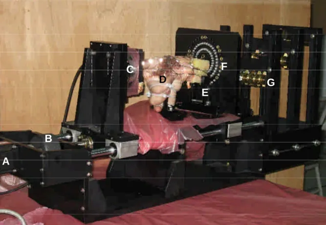
The experimental setup is shown in Figure 2.2. The mounted portion (ulna and radius) was rigidly fixed in front of the multi-apertured plate, and the tip of thumb was pointing to the force sensor. The rest of the fingers (index, middle, ring, and little finger) were secured in straight fist position with the thumb in a neutral posture. Retroreflective markers were respectively glued to the
tip of thumb, the axes of interphalangeal (IP) joint, metacarpophalangeal (MP) joint, carpometacarpal (CMC) joint, and the stylus process of the radius, respectively.
A
B
C
D
E F
G
Figure 2.2 The experimental setup in this study. (A) servo motor; (B) tuner; (C) 6-axis force sensor;
(D) the specimen with hand and part forearm; (E) home-made clamp; (F) guiding plate.
Experiment Procedure
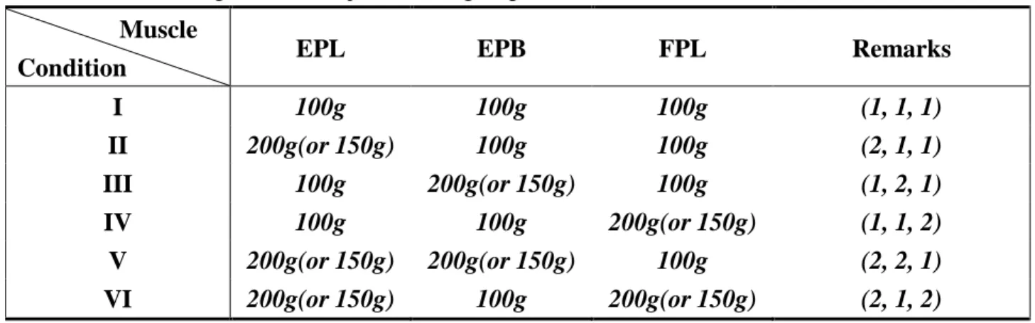
The specimen was placed on the clamping-guiding unit by a custom made clamp specially designed and manufactured for the present study. The eight muscles were assigned to the major muscle group, and the minor muscle group. The major muscle group includes the EPL, EPB, and FPL which are the major muscle to control the thumb to act during flexion and extension. The minor muscle group including APB, FPB, AP, APL and OPP provide stability for the thumb. First, all of the muscles were given force of 50g by hanging the standard counterweights at the far end of the weight and pulley unit. To make the thumb in the neutral posture, we adjusted the angles of joints to align the retroreflective markers in a straight line. Forces acting in EPL, EPB, and FPL were allotted in six conditions as were listed in table 1. The allotted forces within muscles tested were designed to double the counterweights in one or two of three muscles of the major group. One exception was the female specimen which tolerated only up to 150g in EPL. A larger force would throw the IP joint of the thumb into hyperextension condition even when the acting forces in FPL and EPB were also increased to the same magnitude. Thus, a maximum weight of 150 g was applied for this specimen. The reason for changing ratio of these weights respectively in the major group muscles was based on the electromyoghic (EMG) result obtained from these muscles in the
first year study. During the experiment, six different initial force conditions were executed step by step and maintained for a constant duration (20 second) while the thumb posture was recorded by the digital camera. The experiment would be terminated when the IP joint of the thumb either become hyperextended or buckled in flexion.
Table 2.1 The acting force in major muscle group.
Muscle
Condition EPL EPB FPL Remarks
I 100g 100g 100g (1, 1, 1)
II 200g(or 150g) 100g 100g (2, 1, 1)
III 100g 200g(or 150g) 100g (1, 2, 1)
IV 100g 100g 200g(or 150g) (1, 1, 2)
V 200g(or 150g) 200g(or 150g) 100g (2, 2, 1)
VI 200g(or 150g) 100g 200g(or 150g) (2, 1, 2)
Data processing
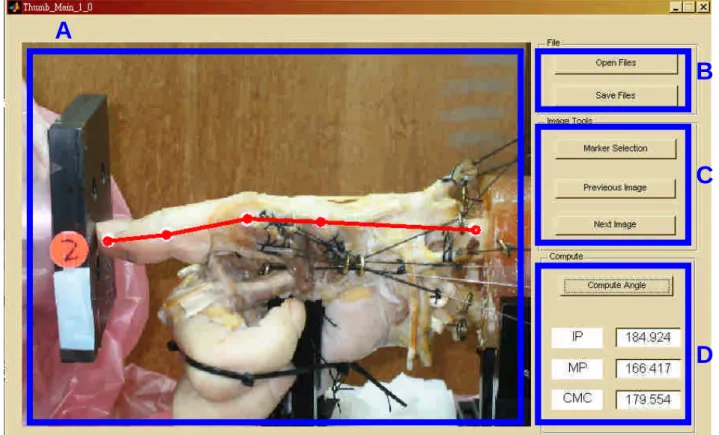
The recorded images were processed by a GUI (graphic user interface) program written in Matlab. The angles of IP, MP and CMC joints were computed for each step of the experiment.
The program automatically connected the markers by four lines, and computed the 2-D angles for each joint. The figure 2.3 is the illustration of the GUI program. The part A is the image process zone, B, the save/load file zone, C, the pick up zone, and D, the computing zone.
A
B
C
D
Figure 2.3. An illustration of the GUI program. (A) the image process zone, (B) the save/load file zone, (C) the pick up zone, and (D) the computing zone.
Results
The changes of IP, MP, and CMC joints, and the maximally resultant thumb tip force were recorded during each loading condition (I~VI) for each specimen (#1~4). Due to the limited number of tested specimens and large variability among specimens, the resulting measures were illustrated for each specimen. Table 3.1~3.4 shows the resultant angles of IP joint, MP joint and CMC joint measured from each specimen, respectively. These angles were separately determined during each loading condition (I to VI) while maximally thumb tip force was recorded.
Before the load cell was pressed on the tip of the thumb, initial position of the three joints involved were aligned as close to the neutral position as possible. However, variability in the initial angle of each joint was noted among specimens during different loading conditions and may result in different joint positioning while maximal thumb_tip force was encountered. Figure 3.2 revealed the differences in initial joint angles (IP, MP, and CMC) during each loading conditions (I~VI), respectively. According to the results, the resultant pattern of IP joint angle during each loading condition was hyper-extension, except during the 4th loading condition. The upper limit for the thumb-tip force registered during the experiment was set to 15 N. The maximal resisted forces obtained from specimen#1 were all close to 15 N (i.e. the maximal thumb-tip force provided by the testing apparatus). Experimental terminating condition for specimen #2 and specimen #4 was IP buckling as a result of instability and, accordingly, the maximal thumb-tip forces were smaller than those terminated due to joint hyper-extension. Joints buckling occurred both on IP and MP joints, and the CMC joint remained at extension. The increase in IP flexion was associated with the decrease in the magnitude of thumb-tip force rather than the angular positions of the MP and CMC joints.
Table 3.1. The resultant IP joint, MP joint, and CMC joint angles resulted by specimen #1 for each loading condition (I~VI). The angles were measured while maximally resisted thumb tip force was encountered or while the unstable force-resisted status of thumb was observed.
Condition IP Joint (degree)
MP Joint (degree)
CMC Joint (degree)
Max. Resisted Force (N)
Resultant Status I
33.48(1.01) -23.53(1.99) -4.31(1.18) 14.67 Hyper ext.II
32.97(1.47) -24.36(3.30) -4.37(0.81) 15.00 Hyper ext.III
30.14(1.10) -21.21(4.45) -2.98(1.82) 15.00 Hyper ext.IV
-25.08(4.03) -23.43(2.73) -3.83(0.03) 8.50 IP BuckleV
32.09(1.28) -23.68(0.42) -0.93(0.16) 14.33 Hyper ext.VI
28.34(3.55) -26.12(0.71) -0.77(0.92) 14.67 Hyper ext.Table 3.2. The resultant IP joint, MP joint, and CMC joint angles resulted by specimen #2 for each loading condition (I~VI). The angles were measured while maximally resisted thumb tip force was encountered or while the unstable force-resisted status of thumb was observed.
Condition IP Joint (degree)
MP Joint (degree)
CMC Joint (degree)
Max. Resisted Force (N)
Resultant Status
I
-9.67(1.56) -8.42(0.39) 12.61(0.84) 5.75 IP BuckleII
-13.42(4.72) -11.47(1.07) 17.96(4.19) 9.67 IP BuckleIII
-12.28(3.20) -9.08(0.69) 15.13(1.49) 4.67 IP BuckleIV
-31.41(10.16) -21.63(2.66) 10.44(0.96) 2.00 IP BuckleV
-30.89(2.81) -8.38(2.13) 20.30(0.91) 7.50 IP BuckleVI
-22.75(7.88) -11.09(0.57) 17.45(0.61) 5.00 IP BuckleTable 3.3. The resultant IP joint, MP joint, and CMC joint angles resulted by specimen #3 for each loading condition (I~VI). The angles were measured while maximally resisted thumb tip force was encountered or while the unstable force-resisted status of thumb was observed.
Condition IP Joint (degree)
MP Joint (degree)
CMC Joint (degree)
Max. Resisted Force (N)
Resultant Status
I
22.56(6.21) -21.43(2.05) 7.56(1.53) 2.67 Hyper ext.II
28.32(4.82) -23.36(3.95) 11.17(2.59) 3.67 Hyper ext.III
24.92(1.86) -26.93(2.70) 14.53(2.27) 4.33 Hyper ext.IV
-33.69 -28.4 14.15 0 N/AV
22.91(4.96) -28.95(4.02) 18.24(3.07) 3.25 Hyper ext.VI
-32.52 -28.4 15.94 0 N/ATable 3.4. The resultant IP joint, MP joint, and CMC joint angles resulted by specimen #4 for each loading condition (I~VI). The angles were measured while maximally resisted thumb tip force was encountered or while the unstable force-resisted status of thumb was observed.
Condition IP Joint (degree)
MP Joint (degree)
CMC Joint (degree)
Max. Resisted Force (N)
Resultant Status
I
-30.55(5.44) -8.54(0.56) -7.28(2.69) 6.25 IP BuckleII
1.13(5.15) -4.29(0.61) -4.19(0.39) 15.00 Hyper ext.III
-28.77(8.15) -8.40(1.08) -5.33(2.94) 5.33 IP BuckleIV
-38.71(4.92) -13.40(0.35) -3.89(1.55) 3.80 IP BuckleV
-3.37(4.11) -5.02(0.48) -5.86(0.76) 14.00 IP BuckleVI
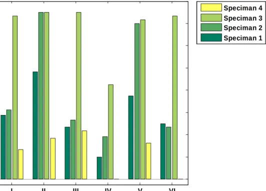
-31.31(7.56) -11.71(0.19) -0.67(2.82) 4.67 IP BuckleThe experimental termination conditions were either the maximally resisted thumb-tip force was achieved or while the unstable status of thumb encountered. There were differences among specimens. Figure 3.1 illustrated the mean resultant thumb-tip forces measured from each specimen during each loading condition. Throughout the experiment, we observed that the experiment terminating conditions were highly associated with initial joint angle rather than changes in muscle efforts.
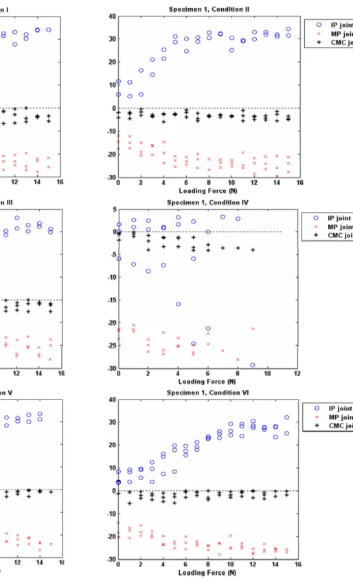
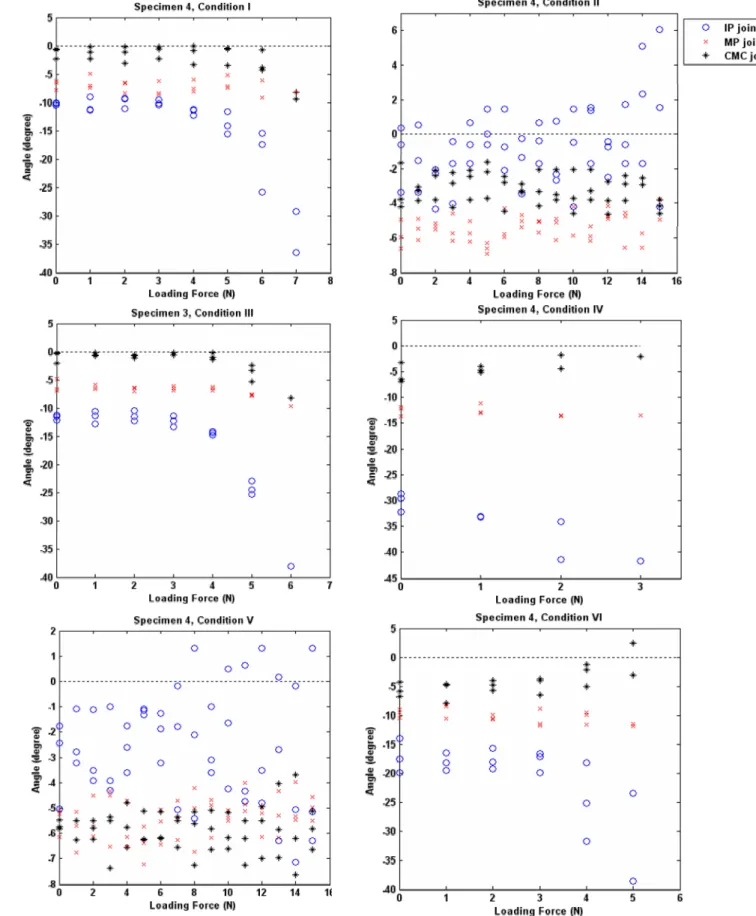
For each loading condition, changes of IP, MP and CMC joint angles for each specimen when the loaded force on the thumb-tip increased (from 0N to maximal resisted thumb-tip force) were showed as Figure 3.3 to Figure 3.6. Large variability was revealed among specimens. For specimen#1, IP extension increased with the increasing thumb-tip load while MP gradually flexed..
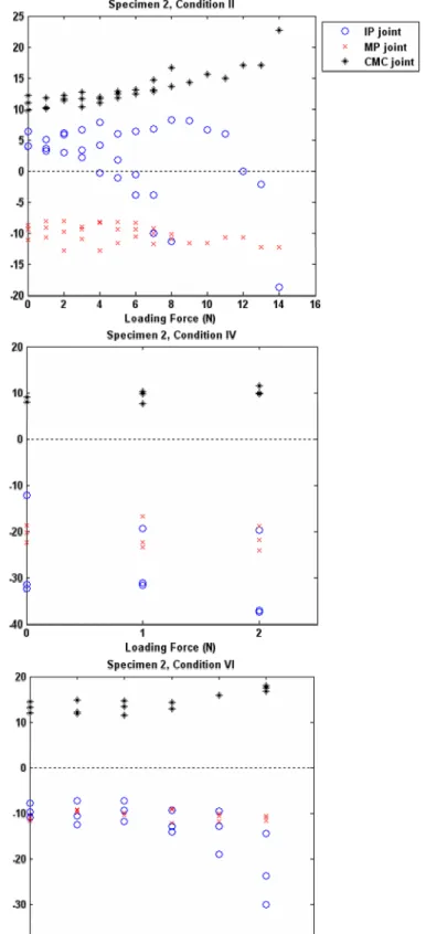
However, the CMC joint remained at neural when the thumb-tip increased. For specimen#2, increase in thumb-tip force was accompanied by increases in IP flexion and CMC extension and eventually resulted in joint buckling and instability. When the applied thumb-tip force is increasing, specimen#3 showed increased extension angles for IP and CMC joints while the MP joint gradually flexed. For specimen#4, increases in applied thumb-tip force caused slight increases in flexion for all joints (i.e. IP, MP, and CMC).
I II III IV V VI
0 2 4 6 8 10 12 14 16
Loading Condition
Max.ThumbTipForce
Speciman 4 Speciman 3 Speciman 2 Speciman 1
Figure 3.1 Comparison of distributions of maximal thumb tip force during each loading conditions for each specimen.
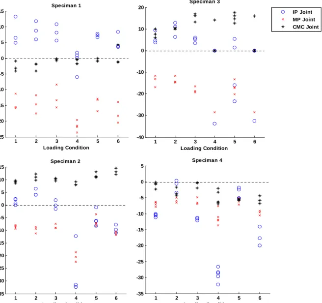
1 2 3 4 5 6 -25
-20 -15 -10 -5 0 5 10 15
Loading Condition
InitialAngle(degree)
Speciman 1
1 2 3 4 5 6
-35 -30 -25 -20 -15 -10 -5 0 5 10 15
Loading Condition
InitialAngle(degree)
Speciman 2
1 2 3 4 5 6
-40 -30 -20 -10 0 10 20
Loading Condition Speciman 3
IP Joint MP Joint CMC Joint
1 2 3 4 5 6
-35 -30 -25 -20 -15 -10 -5 0 5
Loading Condition Speciman 4
Figure 3.2. Differences in initial positioning joint angles (IP, MP, and CMC) during each loading conditions (1~6) for each specimen (# 1~4). Variability in initial positioning joint angles of each joint was revealed among specimen.
Figure 3.3. Changes of IP, MP and CMC joint angles for specimen #1 while thumb tip loading force increased (from 0N to maximal resisted thumb tip force).
Figure 3.4. Changes of IP, MP and CMC joint angles for specimen #2 while thumb tip loading force increased (from 0N to maximal resisted thumb-tip force).
Fi gure 3.5. Changes of IP, MP and CMC joint angles for specimen #3 while thumb tip loading force increased
(fr om 0N to maximal resisted thumb tip force).
Figure 3.6. Changes of IP, MP and CMC joint angles for specimen #4 while thumb tip loading force increased (from 0N to maximal resisted thumb tip force).
Discussion
This study was proposed to evaluate the changes of kinematics and the maximal thumb-tip forces during different loading conditions (I to VI) within the major muscle group of the thumb. The muscles implemented were extensor pollicis longus (EPL), extensor pollicis brevis (EPB), abductor pollicis brevis (APB), flexor pollicis longus (FPL), flexor pollicis brevis (FPB), adductor pollicis (AP), Abductor pollicis longus (APL) and Opponens pollicis (OPP). Based on the experience and the results of previous studies, we try to evaluate the effects of changes in muscle effort of three major muscles, extensor pollicis logus (EPL), extensor pollicis brevis (EPB), and flexor pollicis longus (FPL) on the changes of joint angles (IP, MP, and CMC) when the augmented thumb-tip force was gradually increased. The remaining muscles were loaded by the same weights throughout the experimental procedure. The present results revealed that differences in muscle loading patterns would lead to varied initial joint position (Figure 3.2) and, accordingly, the resultant behavior may vary.
No obvious relationship was found between the maximal thumb-tip forces and the muscle loading patterns applied (Figure 3.1). The experiment conditions mimicked the performing of PA glide without supported (T1 in the previous procedure). Magnitudes of maximum thumb-tip forces were measured while different loading conditions were used to evaluate the effects of muscle efforts on the 2D kinematics and responses to the changes of thumb tip forces. The number of tested specimens was limited in the present study and large variability were shown among specimens.
When a force was applied on the tip of the thumb, the orientation and the initial position of the related joints, especially IP joint, determines the behavior and the stabilizing ability of the thumb joints. While variability was shown among specimens even when the same loading procedure was implemented, patterns of the changes in joint angles for each specimen seemed to be similar irrespective of the muscle efforts applied (i.e. loading conditions, I~VI). According to our results (from Figure 3.3 to Figure 3.6), when IP was extended or was being pushed into extension by the thumb-tip force, the MCP joint was forced into flexion (Figure 3.3 and Figure 3.5) and the CMC joint into extension (Figure 3.5).When IP is initially in a flexed position or being pushed into flexion, the reverse was also found (Figure 3.4). In an attempt to maintain the force loaded on the thumb-tip, the thumb assumed a reciprocal movement between MCP and IP and between MCP and CMC joint. Such inversed angle-angle relationships could be explained by the compensatory movements occurring in the adjacent joints of the thumb during manipulation. It has long been noted that the MP joint compensates for the metacarpal (or CMC joint) flexion-adduction by hyperextension [27, 28]. This means the thumb joint usually compensates the adjacent joint position by reciprocal flexion or extension due to reactive torque created at the opposite ends of the intervening bone.
Limitations of the Study
Several limitations are inherent to the present study. (1) A relatively small number of specimens were studied. There are anatomic variations among cadavers specimens in regarding to the biomechanical characteristics of the soft tissue and the muscle moment arms. These variations results in the large standard deviations seen in the present results. (2) In vitro cadaver kinematics may differ from in vivo kinematics where combinations of differential muscle loadings can occur.
In the present study, we simulated the muscle efforts by loading each muscle with standard weights.
However, the behaviors of changes in joint angle resulted from muscle activation in vitro may be different from what happens in vivo. (3) The maximal thumb-tip forces reported were an average of the entire testing trials and were significantly limited by the testing apparatus used in our study. (4) Differences in the initial positions may alter the behavior of thumb kinematics. When a force was applied on the tip of the thumb, the orientation and the initial position of the related joints, especially, the IP joint, determines the behavior and the stabilizing ability. Although we initially aligned the joints as closed to the neutral position as possible before thumb-tip force was applied, small deviations among trials did occur and led to differences in resultant joint status. (5) The biomechanical characteristics of each joint, such as joint mobility and joint range of motion, were not considered in the present study. The factor related to flexibility of each specimen or of each subject could be seen as a critical factor when assessing the kinematic behavior of each individual during muscular loading or exercises.
Conclusions and Future Work
Based on the results of the present study we documented that the initial joint angles significantly influenced the behavior of thumb joints during thumb-tip loading. The thumb joint usually compensates for the adjacent joint position by reciprocal flexion or extension due to reactive torque created at the opposite ends of the intervening bone. As the thumb-tip load increased, changes in muscle loading patterns resulted in no obvious changes in joint kinematics. Further research works include the modification of the testing apparatus to extend the testing range of the thumb-tip load were necessary. It is also necessary to ascertain the influence of gender and flexibility on thumb tip force generation and their association with the osteoarthritis or pain in the joints of the thumb.
Reference
[1] Sahrmann SA. Diagnosis and Treatment of Movement Impairment Syndromes. Mosby: St.
Louis, Mo, 2002
[2] Maitland G. Vertebral Manipulation, Butterworth & Co, London 1986.
[3] Imaeda T, An K-N, Cooney WP. Functional anatomy and biomechanics of the thumb. Hand Clin 1992;8:9-15.
[4] Moulton M, Parentis M, Kelly M, Jacobs C, Naidu S, Pellegrini V. Influence of metacarpophalangeal joint position on basal joint-loading in the thumb. J Bone Joint Surg Am 2001;83:709-716.
[5] Jonsson H, Valtysdottir S, Kjartansson O, Brekkan A. Hypermobility associated with osteoarthritis of the thumb base: a clinical and radiological subset of hand osteoathritis. Ann Rheum Dis 1996;55:540-543.
[6] Najima H, Oberlin C, Alnot JY, Cadot B. Anatomical and biomechanical studies of the pathogenesis of trapeziometacarpal degenerative arthritis. J Hand Surg Br 1997;22:183-188.
[7] Bork B, Cook T, Rosencrance J, et al. Work-related musculoskeletal disorders among physical therapists. Phys Ther 1996;76:827-835.
[8] Cromie J, Robertson V, Best M. Work-related musculoskeletal disorders in physical therapists:
prevalence, severity, risks, and responses. Phys Ther 2000;80:336-351.
[9] West D, Gardner D. Occupational injuries of physiotherapists in North Central Queensland.
Austr J Physiother 2001;47:179-186.
[10] Wajon A, Ada L Prevalence of thumb pain in physical therapists practicing spinal manipulative therapy. J hand Ther 2003;16
[11] Wajon A. The thumb strap splint for dynamic instability of the trapeziometacarpal joint. J Hand Ther 2000;13:236-237.
[12] Maher C, Latimer J, Starkey I. An evaluation of Superthumb and the Kneeshaw device as manual therapy tools. Austr J Physiother 2002;48:25-30.
[13] Valero-Cuevas FJ, Zajac FE, Burgar CG. Large index finger tip forces are produced by subject independent patterns of muscle excitation. J Biomech 1998;31:693-703.
[14] Cooney III WP, Chao EY. Biomechanical analysis of static forces in the thumb during hand function. J Bone Joint Surg [Am] 1977;59:27-36.
[15] Chao EY, An KN. Graphical interpretation of the solution to the redundant problem in
biomechanics. J Biomech Eng 1978:100:159-167.
[16] Chao EY, An KN, Cooney III WP, Linscheid RL. Biomechanics of the Hand. A Basic Research Study. World Scientific, Singapore. 1989.
[17] Giurintano DJ, Hollister AM, Buford WL, Thompson DE, Myers LM. A virtual five link model of the thumb. Med Eng Phys 1995;17:297-303.
[18] Valero-Cuevas FJ. Predictive modulation of muscle coordination pattern magnitude scales finger tip force magnitude over the voluntary range. J Neurophys 2000;83:1469-1479.
[19] Valero-Cuevas FJ, Johnson ME, Towles JD. Towards a realistic biomechanical model of the thumb: the choice of kinematic description may be more critical than the solution method or the variability/uncertainty of musculoskeletal parameters. J Biomech 2003;36:1019-1030.
[20] Kuo LC, Su FC, Chiu HY, Yu CY. Feasibility of using a video-based motion analysis system for measuring thumb kinematics. J Biomech 2002;35:1499- 1506.
[21] Kuo LC, Cooney III WP, Oyama M, Kaifman KR, Su FC, An KN. Feasibilioty of using surface markers for assessing motion of the thumb trapezometacarpal joint. J Biomech 2003;18:558-563.
[22] Bottlang M, Madey SM, Steyers CM, Marsh JL, Brown TD. Assessment of elbow joint kinematics in passive motion by electromagnetic motion tracking. J Orthop Res 2000;18:195-202.
[23] Gamage SSHU, Lasenby J. New least squares solutions for estimating the average center of rotation and axis of rotation. J Biomech 2002;35:87-93.
[24] Basmajian JV, DeLuca CJ. Muscles Alive: Their functions revealed by electromyography.
Baltimore: Williams and Wilkins, 1985.
[25] Kaufman KR, An KN, Litchy W, Cooney III WP, Chao EYS. In Vivo function of the thumb muscles. Clin Biomech 1999;14:141-151.
[26] KA Krackow, SC Thomas and LC Jones. "A new stitch for ligament-tendon fixation. Brief note." J. Bone Joint Surg. Am. 68:764-766, 1986.
[27] Eaton RG, Littler JW. Ligament reconstruction for the painful thumb carpometacarpal joint. J Bone Joint Surg [Am]. 55(8):1655-66, 1973
[28] Eaton RG, Littler JW. A study of the basal joint of the thumb. Treatment of its disabilities by fusion. J Bone and J Surg. 51A:661-668, 1969