國立臺灣大學工學院材料科學及工程學系 博士論文
Department of Materials Science and Engineering College of Engineering
National Taiwan University Doctoral Dissertation
以固相法製備介電 Ba
5Nb
4O
15及其燒結行為與微波電性
Sintering Behavior and Microwave Property of Ba
5Nb
4O
15Dielectric Material and its Preparation
曹 中 亞 Chung-Ya Tsao
指導教授:段維新 博士 Advisor: Wei-Hsing Tuan, Ph.D.
中華民國 106 年 7 月
July, 2017
誌 謝
走進二號館階梯教室準備論文口試的那一刻,腦海中喚起曾經遊藝在這熟悉校園的回 憶,在即將畢業準備下一個人生起點時,心情是複雜不定的。然而一路走來經過時間淬煉,
27 年後再次踏出校園,我才深刻體會到格物窮理的意義,要達到求知若渴 虛心若愚境界,
必須鞭策自己真正做到堅持不懈和永不放棄。
首先要感謝 段維新教授給我明確的指引方向,指導我如何對實驗中所觀察的現象進行有 系統的分析與闡述,最終將這些紮實的學術訓練由完成論文寫作來呈現。同時要感謝謝宗霖 教授與郭錦龍教授在初次提交論文時提出相當多寶貴意見,使論文內容更加完備。感謝黃坤 祥教授與周振嘉教授專業的指正對未來持續的研究方向有更多發揮空間。同樣地要感謝鼓勵 我不要放棄的老長官 程凌天總經理,因為在職場工作與求學往往是兩條平行線,沒有獲得支 持與鼓勵通常是無法兼顧的。
當然最要感謝在實驗工作上一直協助我的老同事黃曲陵、葉郁蓁女士以及事業部夥伴 們,有他們的幫忙論文內容才能充實完整,也讓努力的痕跡成為論文裡共同記憶。還要感謝 馮奎智博士在共同執行主導性產品開發計劃的卓越貢獻,使論文研究方向得以充分展現。謝 謝系辦林由莉女士不時的叮嚀與課務協助。另外也要感謝明志科大江美貞小姐多次協助 TEM 分析,讓論文中探討晶體結構時有清楚的佐證數據。台大陶瓷複合材料實驗室的學弟妹們,
因為你們的安排使我能在 XPS/FIB/EBSD/XRD 極圖分析等重要實驗順利完成,也謝謝所有協 助樣品分析的工作者。
最後要感謝我摯愛的家人,在漫長又間斷的研修過程,許多煩瑣阻礙了學習動力,茉里 無怨的付出全心照顧家庭,在徬徨時陪伴我一起渡過低潮,在面臨抉擇時支持我去勇敢承擔。
看著致蓁與原輔走入大學生活,已經是知天命之年的我內心只有感恩,我擁有的皆是主所賜,
也將一切榮耀歸於主。 謹以此論文獻給天上的 父母。
摘 要
固相反應製程技術是目前製造介電陶瓷材料的生產方法之一。在眾多微波介電質材料中, Ba5Nb4O15具有高電介質以及低損失特性,可用於低溫共燒陶瓷技術(Low Temperature Cofiring
Ceramic Technology)的選擇材料之一。本研究將分三種方向探討 Ba5Nb4O15材料與固相反應製
程之關聯及影響。
第一階段是探討陽離子空缺型 Ba5Nb4O15材料的高溫燒結行為,在無施加壓力的條件下,
最高燒結密度僅能達到理論值的 93%,當燒結溫度高於 1250°C,密度將隨燒結溫度提升而逐漸 下降,此去燒結現象來自於燒結溫度高於 1250°C 晶粒開始異常成長以及溫度高於 1350°C 後, 鈮離子還原反應所造成。雖然微波特性的介質常數下降,但是品質因子卻可以提高到 40,000 以 上,其原因與鈣鈦礦結構中陽離子晶格有序化程度有強烈的關聯性。
第二階段是探討 Ba5Nb4O15粉末在研磨過程中的機械化學行為。在無球磨粉碎條件下,品
質因子可以提高至 40,000 以上,但是研磨後鋇離子溶出晶格體,產生的 BaCO3結晶物質析出於 水系漿料中,燒結後密度以及品質因子明顯下降。由於微觀結構的燒結晶粒成長具有優選方向, 利用 X-ray 繞射極圖分析以及 EBSD 方法確認(0 0 5)為優選結晶面,與前次實驗相同,米勒指數 (0 1 13)平面的有序化程度與品質因子有強烈的關聯性。
最後階段則是研究少量添加物質 CuO 以及 B2O3的低溫助燒結行為,大幅度地降低燒結溫
度達 400°C 以上,可以將此組成用於與銀共燒結的積層陶瓷結構中,並且無銀擴散反應的現象, 由微觀結構分析確認經過研磨製程也會產生 BaCO3析出物質。
關鍵詞: 微波 ; Ba5Nb4O15 ; 層狀鈣鈦礦相 ; 異方性晶粒成長 ; 晶體結構 ; 化學機械性 ; 優選方向 ; 液相燒結
Abstract
Solid state reaction technique is one of the methods to prepare dielectric ceramic materials. A potential microwave ceramic, Ba5Nb4O15, is the potential candidate of LTCC material. Its microwave dielectric exhibits high permittivity and low loss characteristics. The present study investigates three aspects of this microwave ceramic.
The sintering behavior of the cation-deficient perovskite, Ba5Nb4O15, is investigated in the first part. The highest density can be achieved through pressureless sintering is only 93%. The low sintered density is related to a density decrease, de-sintering, at a sintering temperature above 1250°C. Such de-sintering is contributed by the formation of abnormal grains (>1250°C) and the reduction of niobium ions (>1350°C). Though the permittivity of sintered Ba5Nb4O15 is lower after sintering at a temperature higher than 1400°C, its quality factor is higher than 40,000. The increase in quality factor shows a strong dependence on the cation ordering in the perovskite structure.
The mechanochemical behavior during the milling of Ba5Nb4O15 powder is investigated in the second part. Maximum quality factor >40,000 can be achieved without ball milling. After milling, the precipitated BaCO3 from water base slurry reduces the sintered density, degrades the quality factor. Such precipitate is formed due to the leaching of barium ion from lattice structure. Through the pole figure analysis, the Ba5Nb4O15 (0 0 5) plane is the preferred oriented growth plane. The ordering of plane (0 1 13) shows a strong influence on the quality factor of Ba5Nb4O15 after mechanical treatment.
The last part focus on the effect of a small amount of additives CuO and B2O3 on the sintering behavior. The sintering temperature is reduced by almost 400oC. The cofiring with silver metal to form multilayered structure is then possible. No silver migration is observed when cofire with silver metal. The microstructure analysis confirms the BaCO3 is also formed as resulted from the use of milling process.
Keywords: microwave; Ba5Nb4O15; layered perovskite; anisotropic grain growth; structure;
mechanochemical; preferred orientation; liquid phase sintering
Content
口試委員審定書 ………i
誌謝…….……….... ii
中文摘要……….iii
Abstract………iv
List of Figures………viii
List of Tables………xiii
Chapter 1: Introduction……… 1
Chapter 2: Literary survey………2
2.1 Ba5Nb4O15 crystal structure………..3
2.2 Homogenization of chemical composition with synthesis technology………6
2.3 Densification by liquid phase sintering………9
2.4 Polarization of Ba5Nb4O15 dielectric properties under microwave frequency……….14
2.4.1 Hakki-Coleman method………18
2.4.2 Cavity resonate method………20
2.4.3 Mathematical calculation of permittivity and quality factor………...23
2.5 Ordering Structure of high quality factor……….26
Chapter 3: Sintering Behavior and Microwave Properties of Ba5Nb4O15...27
3.1 Introduction……….27
3.2 Experimental method………..30
3.2.1 Raw material preparation……….31
3.2.2 Experimental flow chart and procedure………..… 32
3.3 Result……….… 35
3.3.1 Weight loss characteristic……….……35
3.3.3 Microstructure and X-ray diffraction………..… 41
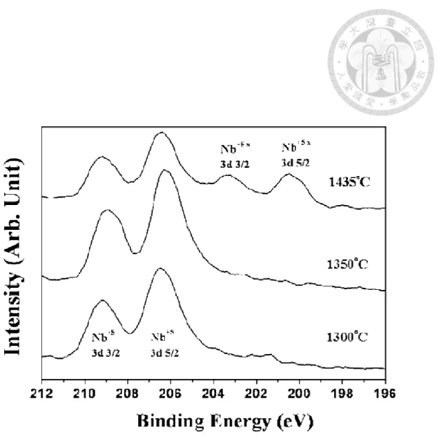
3.3.4 XPS analysis……….52
3.3.5 Microwave characteristic: permittivity and quality factor………55
3.4 Discussion………57
3.4.1 De-sintering phenomena………57
3.4.2 Reduction of Ba5Nb4O15………59
3.4.3 Sintering density vs. microwave characteristic………..62
3.4.4 Ordering of cation and quality factor………63
3.5 Conclusion………67
Chapter 4: Mechanochemical Property of Ba5Nb4O15………68
4.1 Introduction………68
4.2 Experimental method……….69
4.2.1 Raw material preparation………...69
4.2.2 Experimental flow chart and procedure……… …70
4.3 Result………..73
4.3.1 Milling ability of Ba5Nb4O15 powder………73
4.3.2 Leaching phenomena……….77
4.3.3 Interaction with water of milled Ba5Nb4O15 ………79
4.3.4 Anisotropic grain growth………..…82
4.3.5 Weight loss of sintered Ba5Nb4O14………..86
4.3.6 Microwave characteristic……….87
4.4 Discussion………..91
4.4.1 Barium dissociation from lattice site………91
4.4.2 Microstructure vs. Composition……….………..93
4.4.3 Preferred orientation plane by XRD pole figure identification…………96
4.4.4 TEM lattice plane identification………..99
4.4.5 Preferred orientation plane by EBSD identification………..106
4.4.6 Microwave characteristic of milled Ba5Nb4O15……….108
4.5 Conclusion………..110
Chapter 5: Liquid Phase Sintering of Ba5Nb4O15………111
5.1 Introduction………..111
5.2 Experimental method………113
5.2.1 Raw material preparation………113
5.2.2 Experimental flow chart and procedure………...113
5.3 Result and Discussion………...116
5.3.1 CuO and B2O3 sintering additives………..116
5.3.2 Influence of milling process………...………...118
5.3.3 Co-firing with silver metal and microstructure………..122
5.3.4 Electrical properties of low firing Ba5Nb4O15………129
5.4 Conclusion………131
Chapter 6: Conclusion……….132
Chapter 7: Future Work………134
Appendix………..135
Reference………..136
List of Figures
Fig. 2-1 Crystal Structure of Ba5Nb4O15 ………...5
Fig. 2-2 Phase Diagram of BaO-Nb2O5………..8
Fig. 2-3 Illustration of various types of sintering routes……….10
Fig. 2-4 (a) variation of particle growth rate for diffusion-controlled growth………....12
Fig. 2-4 (b) variation of particle growth rate for reaction-controlled growth……….12
Fig. 2-5 Models of polarization………..15
Fig. 2-6 Microwave characteristics measurement methods………17
Fig. 2-7 (a) Hakki-Coleman resonance technique………..19
Fig. 2-7 (b) Cylindrical samples for permittivity and quality factor measurement ………..19
Fig. 2-8 (a) Cylindrical cavity TE01δ resonance technique………...21
Fig. 2-8 (b) TE011 mode Cavity resonance technique………21
Fig. 2-9 Resonated mode of cylindrical dielectric sample under microwave test………..25
Fig. 3-1 (a) 99.9% BaCO3………..31
Fig. 3-1 (b) 99.9% Nb2O5………...31
Fig. 3-2 Experimental flow chart………34
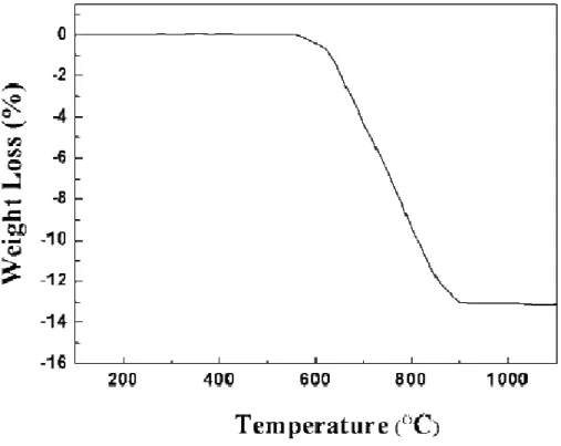
Fig. 3-3 TGA curve for the powder mixture of BaCO3 and Nb2O5 as a function of temperature. The heating rate was 5 °C/min……….36
Fig. 3-4 (a) Morphology of the Ba5Nb4O15 powder prepared by calcination at 1000°C………37
Fig. 3-4 (b) Particle size distribution of pulverized Ba5Nb4O15 powders………37
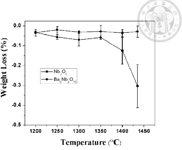
Fig. 3-5Weight loss of Ba5Nb4O15 specimens as a function of sintering temperature. The weight loss of Nb2O5 specimens is also shown for comparison………....38
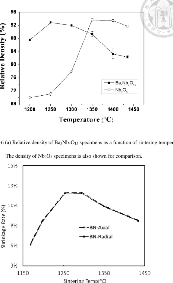
Fig. 3-6 (a) Relative density of Ba5Nb4O15 specimens as a function of sintering temperature The density of Nb2O5 specimens is also shown for comparison………38
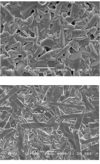
Fig. 3-6 (b) The shrinkage rate of Ba5Nb4O15 specimens as a function of sintering temperature…40 Fig. 3-7 Typical free surface micrographs of Ba5Nb4O15 specimens sintered at (a)1250°C (b)1300°C
(c)1435°C……….43 Fig. 3-8 Typical polished sections micrographs of Ba5Nb4O15 specimens sintered at
(a)1250°C (b)1300°C………44 Fig. 3-9 Typical polished sections micrographs of Ba5Nb4O15 specimens sintered at
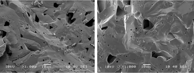
(a)1350°C (b)1435°C………..44 Fig. 3-10 Typical fracture surfaces micrographs of Ba5Nb4O15 specimens sintered at
(a) 1250°C (b) 1300°C………...45 Fig. 3-11 Typical fracture surfaces micrographs of Ba5Nb4O15 specimens sintered at
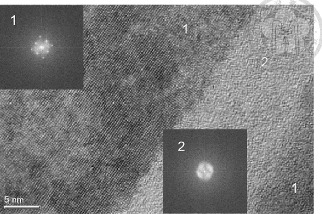
(a) 1350°C (b) 1435°C………45 Fig. 3-12 (a) TEM micrograph of Ba5Nb4O15 sintered at 1350 °C. The bright field image of
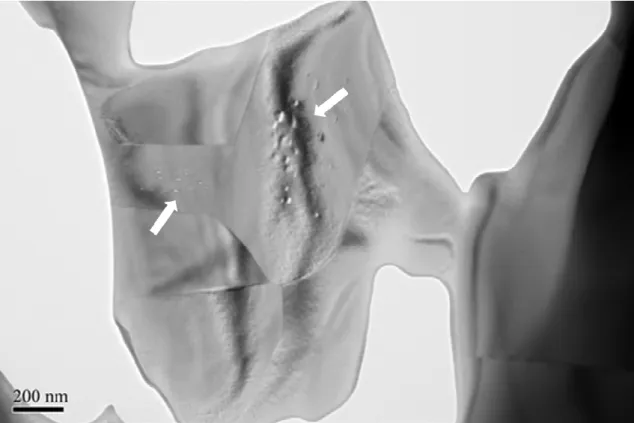
grain (area 2,3) and grain boundary (area 1)………..46 Fig. 3-12 (b) TEM micrograph of Ba5Nb4O15 sintered at 1350 °C. The diffraction
patterns for grain (area 1) and grain boundary (area 2) are shown in the inset……….47 Fig. 3-12 (c) TEM micrograph of Ba5Nb4O15 sintered at 1350 °C. Trapped pores are observed in the grain. (white arrow)………..48 Fig. 3-12 (d) TEM micrograph of Ba5Nb4O15 sintered at 1435°C. Trapped pores are observed in the
grain. (white arrow)………..48 Fig. 3-12 (e) TEM micrograph of Ba5Nb4O15 sintered at 1435°C. Trapped pores are observed in the
grain. (white arrow)………..49 Fig. 3-13 XRD patterns for 2θ from 25° to 70° of the Ba5Nb4O15 powder and sintered specimens.
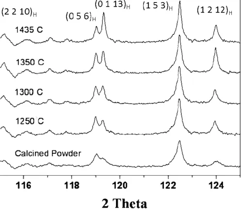
SiO2 was added as the external standard…………..……….50 Fig. 3-14 XRD patterns for 2θ from 115° to 125° of the Ba5Nb4O15……….51
Fig. 3-15 (b) XPS O 1s binding energy spectra for sintered Ba5Nb4O15 specimens...53
Fig. 3-16 (a) Dielectric constant and quality factor for Ba5Nb4O15 specimen as a function of relative density………56
Fig. 3-16 (b) Dielectric constant and quality factor for Ba5Nb4O15 specimen as a function of sintering temperature………...56
Fig. 3-17 (a) The quality factor vs. soaking time of sintering Ba5Nb4O15 at 1300oC………65
Fig. 3-17 (b) XRD intensity of ordering lattice plane vs. soaking time at 1300oC……….66
Fig. 4-1 Experimental flow chart………72
Fig. 4-2.1 Particle size distribution for milled Ba5Nb4O15 powders vs. milling time………..74
Fig. 4-3 Weight loss of Ba5Nb4O15 specimen as a function of milled particle size………..75
Fig. 4-4 Milling media influence on quality factor of Ba5Nb4O15………..76
Fig. 4-5 XRD patterns of the milled Ba5Nb4O15 powder: (111) BaCO3 (a) 0 min (b) 10min (c) 30min (d) 60min (e) 120min ◆:Ba5Nb4O15 ×: BaCO3……….78
Fig. 4-6 Sintered samples of milled Ba5Nb4O15 with different milling time………78
Fig. 4-7 Barium ion concentration after milling……….80
Fig. 4-8 Morphology of BaCO3 precipitated from filtering water of milled slurry……….80
Fig. 4-9 Mechanochemical reaction mechanism of barium ion dissolving in water………81
Fig. 4-10 (a) Free surface of unmill Ba5Nb4O15………83
Fig. 4-10 (b) Free surface of mill 30min Ba5Nb4O15………..83
Fig. 4-10 (c) Free surface of mill 60min Ba5Nb4O15………...84
Fig. 4-10 (d) Free surface of mill 120min Ba5Nb4O15………...…….84
Fig. 4-11 (a) Fracture surface of milled 60min Ba5Nb4O15……….85
Fig. 4-11 (b) Fracture surface of milled 120min Ba5Nb4O15………...85
Fig. 4-12 Milling vs. weight loss and relative density……….86
Fig. 4-13 The relative density vs. permittivity of Ba5Nb4O15………88
Fig. 4-14 Permittivity (K) and quality factor (Qxf) for the sintered Ba5Nb4O15 specimens
prepared using the powders milled for various times…….………89
Fig. 4-15 High angle diffraction pattern of milled Ba5Nb4O15………90
Fig. 4-16 Rittinger’s Law correlation fitting curve of milled Ba5Nb4O15 powders……….92
Fig. 4-17 Simulated anisotropic growth by composition variation……….94
Fig. 4-18 (a) SEM micrographs for the Ba5Nb4O15 sintered at 1435 °C. The cross section from the top of sintered surface reveal specific growing plane without excess BaCO3...…95
Fig. 4-18 (b) SEM micrographs for the Ba5Nb4O15 sintered at 1435 °C. The cross section from the top of sintered surface reveal specific growing plane with excess BaCO3……..95
Fig. 4-19 (a) Comparison of Laue’s diffraction patterns of sintered specimen milled 120min…...97
Fig. 4-19 (b) Comparison of sintered specimen at 1435°C line scans at 2θ angle at 38.15o (red: un-milled black: milling 120min)……….……97
Fig. 4-19 (c) Pole figure of mill and unmill Ba5Nb4O15 with sintering at 1435°C……….98
Fig. 4-20 (a) Bright field image of un-milled specimen at 1350°C………..101
Fig. 4-20 (b) SAED pattern of un-milled specimen at 1350°C……….101
Fig. 4-20 (c) HRTEM Bright field image of un-milled specimen at 1350°C………101
Fig. 4-21 (a) Bright field image of un-milled specimen at 1435°C………...102
Fig. 4-21 (b) SAED pattern of un-milled specimen at 1435°C………102
Fig. 4-21 (c) HRTEM Bright field image of un-milled specimen at 1435°C………102
Fig. 4-22 (a) Bright field image of ion milled specimen at 1435°C………..102
Fig. 4-22 (b) SAED pattern of ion milled specimen at 1435°C………103
Fig. 4-23 (a) FIB preparation for milled 120min specimen at 1435°C……….104
Fig. 4-23 (b) FIB preparation for milled 120min specimen at 1435°C………104
Fig. 4-24 (a) Bright field image of specimen is milling for 2h and sintered at 1435°C………….105
Fig. 4-24 (c) SAED pattern of specimen is milling for 2h and sintered at 1435°C………105
Fig. 4-25 High tilt angle at 70o for EBSD analysis……….106
Fig. 4-26 Band contrast of selected area 300µmX200µm………..106
Fig. 4-27 IPF mapping of milled specimen………..107
Fig. 4-28 Euler Mapping of milled specimen………107
Fig. 5-1 Experimental Flow Chart………115
Fig. 5-2 Milling effect on the sintering density of low firing Ba5Nb4O15………..117
Fig. 5-3 (a) Milling 30min of Low firing Ba5Nb4O15………119
Fig. 5-3 (b) Milling 60min of Low firing Ba5Nb4O15………119
Fig. 5-3 (c) Milling 120min of Low firing Ba5Nb4O15………..………...……...….120
Fig. 5-4 Milling effect on BaCO3 leaching of low firing Ba5Nb4O15………...121
Fig. 5-5 Weight loss vs. milling time at 900oC…………..………..121
Fig. 5-6 (a) 900oC sintering of Ba5Nb4O15 at D50=0.95um (a) free surface (b) fracture surface…..124
Fig. 5-6 (b) 900oC sintering of Ba5Nb4O15 at D50=0.59um (a) free surface (b) fracture surface…..124
Fig. 5-6 (c) 900oC sintering of Ba5Nb4O15 at D50=0.47um (a) free surface (b) fracture surface…..125
Fig. 5-6 (d) 900oC sintering of Ba5Nb4O15 at D50=0.40um (a) free surface (b) fracture surface…..125
Fig. 5-7 (a) TMA experiment compare to low firing and high firing of Ba5Nb4O15……….126
Fig. 5-7 (b) TGA experiment of milling 120 min powder……….126
Fig. 5-8 Ba5Nb4O15 and silver cofiring cross section………127
Fig. 5-9 EPMA of Ba5Nb4O15 and silver cofiring cross section………128
Fig. 5-10 Permittivity vs. Sintering Density of low firing Ba5Nb4O15………...130
Fig. 6-1 Mechanochemical mechanism of barium ion dissolving in water and BaCO3 precipitation ………...………133
List of Figures
Table 2-1 Microwave dielectric measurement method accuracy comparison37……….22 Table 3-1 The different researches on Ba5Nb4O15 sintering properties………..29 Table 3-2 HRTEM-EDX for grain area 1 and grain boundary area 2………47 Table 4-1 Particle size and sintered density of milled Ba5Nb4O15 powders vs. milling time………74 Table 4-2 Grinding media contamination through milling time………76 Table 4-3 Temperature coefficient of resonated frequency at different milling time………109 Table 5-1 List of LTCC high permittivity microwave dielectric materials for LTCC…...………112 Table 5-2 EDX Analysis of A & B Site………120
Chapter 1: Introduction
1. Introduction
The microwave dielectric ceramic materials are introduced into wireless communication industry for many decades. It exhibits attractive performance on high permittivity and quality factor.
It can be applied on oscillator, filter or antenna components designed in high frequency circuit1-3. Additional point of application on endurance issue, those kinds of ceramic material exhibit temperature stability at resonate frequency. It can be near zero variance in extreme climate environment. The microwave dielectric materials were derived from a bunch of oxide ceramics.
They have an advantage of size reduction for microwave components. All of components size depend on the half or quarter-wavelength rule which shorten 1/K1/2 (K: permittivity) length compared in free space. A novel application in miniaturized components must choose a high permittivity dielectric material which conserve energy with less dissipating at microwave frequency.
Many kinds of high permittivity oxide ceramics have been successfully commercialized. The microwave dielectric materials are usually observed in orthorhombic or complex perovskite structure such as Mg1-xCaxTiO3、BaTi4O9、Ba2(TixSn1-x)9O20、ZrxSn1-xTiO4、Ba(Zn1/3Ta2/3)O3、 Ba6-3xRE8+2xTi18O54. A candidate material in the A5B4O15 (A=Ba, Sr, Ca, Mg, Zn ; B=Nb, Ta) system is hexagonal perovskite structure. One kind of material such as Ba5Nb4O15 ceramics has been investigated for its high permittivity and quality factor in microwave frequency4. The merit of Ba5Nb4O15 ceramics is suitable good dielectric constant εr : 38~42 and high quality factor Q×f = 20,000~42,000.
Recently, many researchers approached on low firing Ba5Nb4O15 materials system which introduce glass additives to reduce sintering temperature through liquid phase assistance5. The application of technology aims on firing with silver metal together, the LTCC (Low temperature
Co-fired Ceramics), can put in use for passive component at high frequency circuit. Meanwhile studying on co-firing of the dielectric and conductive metal materials is needed. Such as shrinkage mismatch, silver migration and mechanical strength of ceramic body are always of interests for commercialized manufacturers. But the process effects on characteristics of Ba5Nb4O15 material are less reported in the past years. In this sense, studying on high temperature sintering of Ba5Nb4O15
ceramic is a rational solution. The abnormal grain growth and relative density contravene as a function of temperature saying de-sintering phenomena usually illustrated on reports6. There is little report on the de-sintering mechanism. However, an approach on measuring ceramic density as a function of temperature and microstructure observation is the basis route of study.
On the other hand, there are many routes to homogenize ingredients, milling process is the basic solid-state route to manufacture ceramic materials powders using intensive mechanical energy.
Regardless minor chemical impurity of raw materials, BaCO3 and Nb2O5 sources are recommended by high purity level. Several technique procedures for ceramic powder preparation, such as milling / drying and calcination process, have been investigated in the past few decades. Eventually, the characteristics of Ba5Nb4O15 strongly relate to effect of process parameters. In our studies, the de-sintering phenomena of Ba5Nb4O15 was observed and the mechanochemical characteristic along milling process. The investigated root cause of such properties can be analyzed quantitively and mechanism was proposed.
For the applications of LTCC technology, Ba5Nb4O5 with sintering additives can be cofired with silver metal which has been commercialized to make RF components. In our studies, the de-sintering and precipitation of BaCO3 after milling process can be verified by microstructure at low sintering temperature.
Chapter 2: Literature Survey
2.1 Ba5Nb4O15 crystal structure
Most of microwave dielectrics materials with electrophysical properties are oxide ceramic systems7. One of them was surveyed on A5B4O15 (A=Ba,Sr,Mg,Ca ; B=Nb,Ta) oxide compounds were the cation deficient hexagonal perovskite structure which vacant existence on B ions lattice site. The formula can be reduced to AB0.8O3 by accommodated charge neutrality between A and B metal cations. In general, the ideal structures can be classified to cubic perovskite structure ABO3
that octahedral corners were shared by BO68-9. Compared to ideal cubic perovskite structure, it can be stacked along principle axes like layer-orientation perovskite structure. The stacking sequence are 1B cation vacancies per 5A cation means 20% of B cation site is occupied by vacancy and 5 layers stacking to be ABO3.
Ba5Nb4O15 compounds is classified to space group P-3m1 that can be close packing in five-layer sequences with shift type arranging the oxygen and barium atoms. Fig. 2-1. Ba5Nb4O15
belongs to cation deficient perovskite structure type that lattice size is a = 5.8065Å and c = 11.8227Å. It is the crystal data collection and refinement from X-ray analysis. These compounds are hexagonal symmetry and has been identified as a layered structure which stacking plane parallel to {111}c (c = cubic). On the corner of Ba5Nb4O15 lattice were structurally shared by NbO6 octahedral and with the barium atom in the center of the cube surrounded by the niobium atoms. According to Goldschmidt’s tolerance factor rule as equation (1)10, the stability of lattice structure strongly relates to the distance of cation-anion bond at equilibrium state.
t = d(Ba-O) / [21/2 ⤫d(Nb-O)] ………. (1)
Corner sharing of NbO6 octahedral can eliminate the repulsion force between cations, meanwhile, the cation-anion distances create stress in the lattice. The tolerance factor can be
identified to lattice structure, relaxation of bond energy will result in twisting of NbO6 octahedral.
For Ba4Nb5O15 the tolerance factor (γBa≈149pm, γNb≈78pm, γO≈120pm) is calculated to t >1, finally niobium ions are tilted out of the octahedral center of NbO6 to form hexagonal type perovskites structure. There is a strong anharmonicity distort the lattice structure from empty octahedral site of NbO6 sub-lattice. The reduction of symmetry can lower energy and distort geometrically by d-shell orbitals from Jahn-Teller theorem42.
The cation-deficient perovskite structure is attractive dielectric material applied to the microwave properties. A5B4O15 dielectric ceramics system11 reveal high relative permittivity (εr) with good quality factor (Q) and low temperature coefficient at resonator frequency (τf).
Sreemoolanathan et al.12 studied hexagonal structure of Ba5Nb4O15 microwave dielectric ceramic proved its εr = 39, Q×f = 24,000 and τf = 78 ppm/°C. The structure of crystal symmetry exhibits five layered close-packed planes with Ba, Nb and O atoms sequentially. There is one layer plane without Nb atom has hexagonal packing which belongs to cation deficient perovskite structure. The microwave permittivity of the Ba5Nb4O15 ceramics can be determined by the polarized phonon anomalies and related to density of ceramic body. The permittivity and quality factor can be varied by substituted atoms such as Sr or Ca atoms in A site to modify the symmetry of crystal. Many researchers on cation partial substitution on A5B54O15 crystal can tailor the microwave dielectric properties and sintering characteristic13-14. As the composition of cations are strongly related to the stability of resonated frequency following temperature variation,
Fig 2-1. Crystal Structure of Ba5Nb4O15
P-3m1 No.=164 Hexagonal Perovskite a = 0.58065nm
c = 1.18227nm Density: 6.245 g/cm3
2.2 Homogenization of chemical composition with synthesis technology
Many synthetic processes can be applied on making ceramic products with different ingredients.
The merit of process always relies on the product performance and economical benefit for end user.
From the thermo-kinetics point of view, to shorten the synthesis time convert reactant to another substance, the driving force applied on homogenizing ingredients are physical length and temperature under atmosphere. Solid state process always is a simple and favorable technology to synthesis substance as following multistep process from mixing-drying-calcination-pulverization of powders in ceramic industry. Each process step derive from the principal of chemical physics theory will affect the final characteristics of substance. Such as the raw materials properties are chemical formula, particle size and impurity level, the mixing treatment for homogenizing compositions are physical energy of mechanical mixing technology and calcination technology of controlling temperature and atmosphere. The basic phase formation of Ba5Nb4O15 has been published on the Fig. 2-215.
Simply statement of solid state process is so-call most of ingredients from powder forms and mixing by mechanical forces assisting with media. The mixed reactants will be homogenized by external force from temperature treatment. Their substances exhibit state of the art characteristics predictably. Most of interests for academic study do not focus on process research of synthesis technology. There are many troubles for industry application such as yield and degrading of characteristics withstanding severe environment. The Ba5Nb4O15 is the candidate of microwave dielectric material but the performance and some physical properties is not the best choice one. Only low fired material system of such kind dielectric material has been commercialized16.
No matter what kinds of ceramics material is existed, the product is prepared from solid state
There are aqueous or none aqueous conditions can play the role of lubricant and intermedia phase of ingredients engage reaction17-18. This kind of processing route has been applied for functional ceramics compounds. The reaction temperature can be reduced by activated mechanical energy through chemical reactivity of raw material. The mechanochemical phenomena happened in many oxide ceramics effected on microstructure and physical properties. The mechanical energy can be generated by speed of rotation, prolonging time and media in raw materials. It was clear that crystalline size or particle size would be reduced when increase the mechanical energy. The mechanical energy leads to form a new surface with high strain on particles can be released under the solid state chemical reaction. The solid-state synthesis technology can be improved by this novel mechanochemical treatment to form Ba5Nb4O15 ceramic. The dielectric properties of sintered Ba5Nb4O15 ceramic can be compared to those prepared by different milling time in this study. In this stage, the vehicle plays another role of chemical ingredient to contact new free surface as a reactant.
There is more chemical gradient to enhance energy exchange during these processes contributed by mechanical activation. The purpose of the present study is to verify the mechanochemical effects of Ba5Nb4O15 ceramic materials on microwave dielectric properties and sintering characteristic.
Fig 2-2. Phase Diagram of BaO-Nb2O5
Fig 2-2. Phase Diagram of BaO-Nb2O515
2.3 Densification by liquid phase sintering
In general, the ceramic material sintering technique can be grouped two kinds process, solid state sintering and liquid phase sintering, used to control the powder densification. The purpose of sintering is microstructural control as to be dense body fitting material property or performance.
Kang19 illustrated the sintering route from phase diagram in Fig. 2-3. There are four kinds of sintering routes based on solid to liquid phase mass transportation. As a thermal dynamic equivalent diagram, the sintering temperature T1-T3 near to phase transformation line of different phases exhibits different sintering mechanism. Basically, the phase diagram of BaO-Nb2O5 oxide ceramic is proposed on attached Fig. 2-215 and melting point of Ba5Nb4O15 is near to 1547°C. If sintering temperature of Ba5Nb4O15 under 1342°C confirmed to be solid state sintering but it will occur probably liquid phase sintering near the solidification line of a stoichiometric composition.
Fig 2-3. Illustration of various types of sintering routes19
Liquid phase sintering (LPS) is a well esatablished method to reduce sintering temperature accomplish powder densification in the presence of a liquid. There are several theories of LPS describe the densification stages such as German and Kingery model20-22. Obviously microstructure development of sintered dense body gives an evidence of LPS process from identification of interfacial grains. To illustrate the abnormal grain growth phenomena at final stage of grain growth23, it is controlled by diffusion of atoms and reaction of liquid/solid interface. The description proposed by Lifshitz, Slyozov and Wagner is named LSW theory24-25. The assumption of LSW theory can’t explain the oriented grain growth. Faceted grains growth is governed by interface reaction that each crystallographic plane has certain diffusion coefficient varies with its orientation.
The behaviors of grain growth can be simulated numerically if it is growing or dissolving at a critical size. The grains growth is simplified as equations derived from two kinds of mechanisms.
Fig. 2-4 (a)~(b)
From the grain growth point of view, it is obviously diffusion or reaction controlled atoms dominate the grain. For grain growth rate on different crystallographic orientations based on the interfacial energy, the low interfacial energies appear slowly growing planes. Usually the simple polyhedral or anisotropic grain shape are belonged to reaction-controlled growth. On the other hand, a fast dissolving planes reveal a high interfacial energy for anisotropic grain growth.
Fig. 2-4 (a) variation of particle growth rate for diffusion-controlled growth19
.
Fig. 2-4 (b) variation of particle growth rate for reaction-controlled growth19
In the innovative technology by the presence of liquid phase, many kinds of sintering additives can play the role to enhance chemical reaction or increase diffusivity on the primary powders.
Usually the particular additives were selected from ingredients of phase diagram. All of varied compositions were examined the relative density after a firing procedure. Many researches on additives to lower sintering temperature of Ba5Nb4O15 material have been commercialized by LTCC technology26-28. The mains liquid phase sintering additives such as B2O3, CuO and glass dopes can reduce the reaction free energy. The sintering temperature is under 900oC that Ba5Nb4O15 cofire with silver metal. This system occurs to reduce the interfacial energy of chemical composition associate with matrix and solute composition. As a result, there is an activation energy for the total area of boundary to be reduced by solution and precipitation in liquid phase. The grain coarsening in the final stage of sintering accompanied was always verified from microstructure evolution.29-30
2.4 Polarization of Ba5Nb4O15 dielectric properties under microwave frequency
The behavior of Ba5Nb4O15 microwave dielectric material has the macroscopic polarization which are formed by an inherently permanent dipole orientated dependence with the direction of the external electric field. The polarization is not instantaneous and need time to recovery the storage energy when release the applied field. Ba5Nb4O15 can exhibit a low dissipated energy when dipolar polarization lost the response to electric fields at the highest frequencies.
In the presence of an oscillated electric field, the dielectric materials are polarized to dipole moment in the filed act like clouds charge. A classical dielectric model at different frequency of electric field oscillation can be classified by the dielectric material with four types models. The polarization model is varied by the relationship between the frequency of electric field and dipole moment. When the frequency of electric field is higher, the dipole moment tends to be the model from ionic to electric polarization. The essence of model in physics are summarized to be (a) space charge (Maxwell Wagner effect): Interfacial polarization which build up the charge at the interface (b) dipolar polarization: A permanent dipole result from electric field (c) ionic polarization: relative displacement of nuclei due to separation of positive and negative field (d) electronic polarization:
arises from the realignment of electrons in the specific nuclei31. Fig. 2-5. In the electromagnetic spectrum range, microwave frequency extends the carrier wave range from 3MHz to 300GHz which correspond to wavelength between meter to millimeter scale respectively. The electromagnetic radiation wave will interact with condensed matter induce the vibration of lattice. The condensed matter will be polarized by electromagnetic wave like charge carriers are bound to relative displacements between positive and negative field.
Fig 2-5. Models of polarization
Microwave measurement techniques applied for permittivity and dielectric loss properties can be categorized to transmission-reflection and resonance methods32-34. In generally, the resonance method was classified two types of resonate models in closed cavity and open resonator Fig.2-6.
This resonator model was constructed by conducting metal and lossy geometric structure which can be measured under microwave region. Due to microwave range energy is reduced by the conductive or magnetic material in the space, the incident EM wave propagation nearly reflected and the metallic case shields electromagnetic wave with preventing radiation loss. Both of the dielectric constant and loss factor can be deduced from the resonant frequency under a typical size. For industry application viewpoint, only easy and simple measurement method can be introduced to standardization procedure. Two most commonly used measurement methods are mainly introduced to microwave dielectric material applied to electromagnetic wave frequency under 40GHz.
Fig 2-6. Microwave characteristics measurement methods
2.4.1 Hakki-Coleman method
A general post-resonance technique which was similar to parallel metal plate proposed by B.W Hakki and P.D Coleman in 1960 for measurement of dielectric constant35. The dielectric constant is computed the inductive and capacitive of reactance at resonate TE011 mode derived from cylindrical dielectric sample36-37 Fig. 2-7. It is complicated calculations for mathematical function which derived a complex Besell’s equation to get the real part of permittivity by computer program. The measurement accuracy is higher that variation error under 0.5% and can be available to high permittivity material. Only one disadvantage of the method was low measurement accuracy of loss factor that the surface resistance of metal plates could affect the conductivity. To overcome the term of conductivity in the derived equation, two dielectric samples with TE011 and TE012 mode must be measured with the same material size. This method has been standardized under the regulation rule of JIS R1627 and IEC-61338-1-3.38-39
Fig 2-7 (a) Hakki-Coleman resonance technique36
Fig. 2-7 (b) Cylindrical samples for permittivity and quality factor measurement37
2.4.2 Cavity resonate method
Whatever the development of electromagnetic field computation, for simplifying measuring structure, the dielectric resonator is designed as a cylindrical type. The rod sample is placed inside a closed metal cavity. The waveguide reflection resonance mode in the cavity can get a highly accurate measurement for dielectric loss which resultant low conducting loss. Due to the samples suspended inside the metal shields and all resonated radiation wave conserved in the case, the conductor loss will be lower than that of Hakki–Coleman technique.
J. Krupka40 proposed a simplified cylindrical metal cavity which restrict size of the sample and height of resonator cavity for measuring the resonate peak with the TE01δ mode. The calculation equations for the dielectric properties are more easily derived than those of other modes. Referring to the cylindrical cavity structure in Fig. 2-8 (a)&(b), both of distance on top and bottom of sample to metal case are nearly equal. The TE01δ mode resonated peak is easily identified from sweeping spectrum but lack of exact solutions of Maxwell’s equation as same in parallel plate structure. The cavity structure family of dielectric resonator for precise measurement can be equipped with Vector Network Analyzer. It is installed specialized calculation software for determination of complex permittivity and quality factor of microwave dielectric material.
However, cavity resonant method can extract TE011 mode by the presence of a sample in the cylindrical cavity as Fig. 2-8. The plate type of dielectric sample cause to electric field perturbation when inserted in the metal cavity. That measurement method was committed to standardization regulation under the JIS R1641, IEC62562 (Plate)
Fig. 2-8 (a) Cylindrical cavity TE01δ resonance technique36
Fig. 2-8 (b) TE011 mode Cavity resonance technique37
Table 2-1Microwave dielectric measurement method accuracy comparison37
εr tanδ σr
∆εr [%] ∆tanδ [%] ∆σr [%]
JPCA-FC01(2006) 1.1~10 10-2~10-4
JFIA-FP001(2006) ±0.2~1.0 ±5~20
JIS R 1641 (2007) 1.1~50 10-3~10-6
IEC 62562 (2009) ±0.2~0.5 ±2~10
JIS R 1660-1(2004) 1.1~50 10-3~10-6
IEC 61338-1-4(2005) ±0.2~1.0 ±2~10
JIS R 1627(1996) 2~1000 10-3~10-7 10~100
IEC 61338-1-3(1999) ±0.2~0.5 ±5~20 ±2~10
- - 10~100
- - ±5~15
1.1~50 10-2~10-4
±1.0~7.0 ±10~30 εr tanδ
εr tanδ
εr tanδ
εr tanδ εr tanδ Rsf σr Rsf σr
Rod Plate Conductor
2~65
2~40
30~100
2~30
2~30
TM010 mode cavity 1~30 resonate
Plate
Plate
Cylinder
f0 [GHz]
Parameter Sample
Regulation STD Type Measurement Method
Disk Parrallel Plate
Cavity Resonate
Wave Guide
Dielectric Resonate MIC type dielectric resonate
2.4.3 Mathematical calculation of permittivity and quality factor
To standardize the permittivity and quality factor measurement method in commercialized regulation, the dielectric resonate method has been published on JIS R1627(1996) and IEC61338-1-3(1999). When electromagnetic wave propagates in the space to conserve the energy, the resonance phenomena occurs at the waves travel at different regions such metal and low-loss materials medium. The shape of resonator represents the boundary of wave function geometrically such as rectangular or cylindrical configurations. In general, a cylindrical type resonator is easily obtained by ceramic forming process. This resonate structure can be used to generate oscillation at specific frequency. The frequency was indicated to calculate εr from equation (1) and tan δ of low-loss material sample from equation (3) mathematically.33-34
εr = (λ0/πD)2(u2+v2)+1 λ0= c / f0 ……… (1) v2 = (πD/λ0)2((lλ0/2L)2-1)
J0(u) / J1(u) = - vK0(v) / K1(v) ……… (2)
c: light velocity in vacuum D: diameter of specimen L: height of specimen Jn(u): Bessel function of first kind Kn(v): Modified Bessel function of second kind tan δ = A / Qu - BRs ……….. (3)
A = 1+W/εr B = (lλ0/2L)3(1+W)/(30π2εrl) Rs = (πf0µ/σ) 1/2
W = [J12(u) / K12(v)] [K0(v)K2(v) -K12(v)] / [J12(u) –J0(u)J2(u)]
Qu = unload Q Rs = surface resistivity of metal plate
Both of characteristic were obtained from resonated frequency values f0 and peak spectrum with half power band width of 3dB attenuation. The unloaded quality factor Qcan be deduced from loaded quality factor which formed as Maxwell wave equation in cylindrical coordination. A
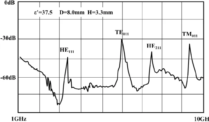
complicated Bessel equation can be treated as scalar Helmholtz equation by separation of variables method. Remained Bessel equations can derive the radial direction of rod for both real and imaginary parts. Finally, the ratio of Bessel’s first kind and modified Bessel’s second kind equations (2) can be derived by graphical or numerical methods. The resonated electromagnetic wave travelling in a waveguide can possibly propagate several modes. The dominant mode has the lowest cutoff frequency is determined by the physical dimension. For example, transverse electric field (TE) mode means no electric field in the direction of wave propagation. It happened at certain frequency which boundary condition has radiation wave pattern can be described in term of transverse mode. Such as a K=38 with 8mm diameter 3.8mm height dielectric material was measured under Hakki- Coleman method, the resonated mode of full spectrum frequency can be observed by Network analyzer in Fig. 2-9. When select the TE011 mode frequency f0 and confirmed the second twice height cylindrical sample with TE012 mode f02, the permittivity εr and dissipated factor tan δ can be derived by computer program.
Fig. 2-9 Resonated mode of cylindrical dielectric sample under microwave test
2.5 Ordering structure of high quality factor
There are a large number of A- or B-site vacant perovskite materials applied for microwave application. The crystal structural ordering of ceramics always improved the microwave dielectric properties especially for low loss cation deficient perovskite materials41. Fundamentally from crystallographic chemistry point of view, there are three mechanisms express the perovskite distortion including orbital ordering (Jahn-Teller distortion)42, cation ordering and octahedra tilting43-44. The deficient cations cause ideal perovskite structure distorted and driven by electronic instabilities of the octahedral metal ion. The crystal distortion often combined effects of those mechanisms in structural features. The bond between B-O of BO6 has a strong electronegativity to be rigid structure maintains its core-share connectivity. Only tilting the octahedra can contribute an energetic stabilization to be lowest energy distortion mode45. The internal strain derived from lattice distortion affects the polarization loss factor which can be varied non-linearly by cations concentration. Meanwhile, the dielectric constant and the temperature coefficient of the resonant frequency linearly changes with the composition. Internal lattice strain can be verified usually by FWHM of X-ray diffraction pattern but it is hardly achieved. Sometime the superlattice ordering is an indication of Q factors enhanced by the driving force from long time temperature sintering. The intensity ratio of a superlattice peak to a fundamental peak of x-ray diffractometry (XRD) is the method for evaluating the degree of ordering. The order parameter, S, which is calculated from the observed and calculated values of the superlattice peaks intensity ratio46.
S = {[I(superlattice A)obs/I(fundamental B)obs] ÷ [ I(superlattice A)cal/I(fundamental B)cal]}1/2 The degree of structural order from ratio of plane intensity has been generally considered to identity Q factors improvement quantitatively.
Chapter 3: Sintering Behavior and Microwave Properties of Ba
5Nb
4O
153.1 Introduction
Microwave dielectric ceramics had a good quality factor were always sintered at high temperature. They can be applied widely on wireless communication industry demanded for filter, resonator and antenna components. A novel application in miniaturized components must choice a high permittivity dielectric material due to the wavelength decrease in the medium. The high permittivity microwave material Ba5Nb4O15 has been commercialized. The merit of Ba5Nb4O15
ceramic exhibits its economical application for good dielectric constant and quality factor.
A cation-deficient perovskite47-48, Ba5Nb4O15, has attracted a lot of attention in last two decades. Though Ba5Nb4O15 reveals the advantage on microwave properties, the preparation of dense of Ba5Nb4O15 through pressureless sintering is a challenging task. Apart from Ba5Nb4O15
perovskite, the existing literatures demonstrated that the abnormal grain growth and density decrease during high temperature sintering (de-sintering) are common for other microwave ceramics.
For example, both abnormal grain growth and de-sintering at elevated temperatures are found for Ba(Zn1/3Ta2/3)O3. Similar to the case of Ba5Nb4O15, little attention has been paid to these important issues.
The microwave performance of perovskite depends strongly on its intrinsic and extrinsic characteristics. The crystallographic structure belongs to the intrinsic characteristic; the microstructural features to the extrinsic characteristics. As far as the permittivity and quality factor are concerned, the amount of pore is the key parameter. Both permittivity and quality factor decrease with the increase of porosity. In this chapter study, the sintering behavior of Ba5Nb4O15
perovskite is investigated. The microstructure and crystalline structure are characterized. The effect of sintering on microwave performance of Ba5Nb4O15 perovskite is then established.
Microwave characteristics of different researchers studied on sintered Ba5Nb4O15 were compared in the Table 3-1. All examined results of dielectric samples were clearly performed on high relative density. The difficulty of getting high relative density was overcome by sintering technology. Adding sintering additives and lowering sintering temperature treatment can avoid the matter of fact in abnormal grain growth. Why has abnormal grain growth and what happened in de-sintering at high temperature are our interests for investigation in this study.
Table 3-1 The different researches on Ba5Nb4O15 sintering properties Sintering
Condition
Relative Density
Permittivity K
Quality F.
Qxf Remark Reference
1420°C4Hr 92.0% 41 7,100 No Additives Streemoolanathan12 1250°C2Hr 97.5% 40 56,000 B2O3/V2O5
Additives Kim13
1450°C4Hr 97.3% 39.5 22,700 None
Calcination Chen17 1380°C2Hr 96.0% 39 23,700 No Additives Jawahar73
1250°C5Hr 97.3% 34 32,000 None
Calcination Kumar18
3.2 Experimental
3.2.1 Raw material preparation
Samples of Ba5Nb4O15 ceramics were prepared by conventional solid state reaction route. The starting materials were BaCO3 and Nb2O5. and purity level was higher than 99.9%. The morphology of raw materials revealed in Fig.3-1 (a) & (b). Confirming both initial properties of raw materials were checked by particles size analyzer (LA-920, Horiba Co., Japan) and morphology by scanning type electron microscope (JSM-6360, JEOL Co., Japan). Both BaCO3 and Nb2O5 materials weighted in stoichiometric mole ratio 1.000 are mixed with distilled water. The milling media was 2mm zirconia balls and planetary mill rotated 220rpm in 30min. The mixed slurry then dried and pressed powders into 25mm cake were calcined at 1000°C for 2.5 hours. After drying, the powder mixture was packed into cakes with a diameter of 25 mm. The weight loss behavior of the powder mixture at elevated temperatures was evaluated with a thermogravimetry analysis (TGA, MTC-1000S, Mac Science, Japan). The heating rate used was 5 °C/min. Based on the TGA result, the calcination for the BaCO3 and Nb2O5 powder mixture was carried out at 1000°C for 2 h. The calcined cakes were pulverized by agate mortar to obtain the Ba5Nb4O15 powder. The particle size was analyzed with a laser size analyzer (LA-920, Horiba Co., Japan). Furthermore, the calcined Ba5Nb4O15 cake pulverized by agate mortar and milled to 2.3um.
Fig 3-1 (a) 99.9% BaCO3
Fig 3-1 (b) 99.9% Nb2O5
3.2.2 Experimental flow chart
The source of the Ba5Nb4O15 calcined powder was prepared under pulverized process without wet milling in water. For ability of ceramic powder granules were formed as usual in the mold. The powder compact was prepared by uniaxial pressing at 140 MPa, assisting with the addition of a small amount (4 wt.%) of PVA. The relative density of the green Ba5Nb4O15 powder compact is 64
%. The diameter of the green pellets was 10 mm; the thickness was 2.0 mm. The de-binder temperature was 600°C. The sintering temperature varied from 1200°C to 1435°C. The dwell time at the sintering temperature was 2.5 h. The heating and cooling rates were 2.5 °C/min. The weight before and after sintering was monitored. Some Nb2O5 specimens were also prepared by sintering at 1200°C to 1435°C for comparison purpose. For each sintering condition, at least 10 specimens were prepared. The density of the fired discs was determined with Archimedes method. The relative density of the sintered specimen was calculated using a value of 6.25 g/cm3 for the theoretical density of Ba5Nb4O15. The phase analysis was conducted with an X-ray diffractometer (XRD, D8, Bruker Advance, Germany). Two ranges were scanned, the scanning rate for lower angle range (25~70o) was 0.04 degree/step and 1 s/step; for higher angle range (115~125o) was 0.01 degree/step and 2.0 s/step. Before the XRD analysis, the sintered specimens were crushed into powder. A small amount (5.0 wt.%) of silica was pre-mixed with the powder to serve as an external standard for the XRD analysis.
Microstructure observation was conducted with scanning electron microscopy (JSM-6360, JEOL Co., Japan) and transmission electron microscopy (JEM-2100, JEOL Co., Japan). For SEM observation, the cross-section of the sintered specimens was exposed by grinding and polishing. A thermal etching treatment was conducted at 1200°C to reveal the grain boundaries. For TEM
microwave characteristics of the sintered specimen were analyzed with a network analyzer (HP-8720ET, Agilent, USA) following a standardized Hakki-Coleman and Cavity method. To verify the phenomena of de-sintering and deduce the reduction of cation may happen at high temperature. The binding energy state of niobium ions and in the sintered Ba5Nb4O15 specimen was determined with X-ray photoelectron spectroscopy49 (XPS, ESCALAB 250, Thermo Scientific, UK).
Fig. 3-2.
Fig. 3-2 Experimental flow chart