CREATION OF TILE-OVERLAPPING MOSAIC IMAGES FOR INFORMATION HIDING
Tsung-Chih Wang (王宗志)1
and Wen-Hsiang Tsai (蔡文祥)
2,31
Institute of Multimedia Eng., National Chiao Tung University, Hsinchu, Taiwan
2
Dept. of Computer Science, National Chiao Tung University, Hsinchu, Taiwan
3
Dept. of Computer Science & Information Eng., Asia University, Taichung, Taiwan E-mail: [email protected], [email protected]
ABSTRACT
A method for creation of a new-style mosaic image, called tile-overlapping mosaic image, for the purpose of information hiding is proposed. Each tile- overlapping mosaic image is created by varying the overlapping degrees of the adjacent rectangular constructing units - tile images. A secret binary data stream is embedded into a cover tile-overlapping mosaic image by utilizing the overlapping degrees of adjacent tile images. And data recovery is accomplished by detecting the overlapping degree of every pair of adjacent tile images in the resulting stego-image.
Experimental results show the feasibility of the proposed method.
Keywords: art image, tile-overlapping mosaic image, information hiding, covert communication, copyright protection.
1. INTRODUCTION
Non-photorealistic rendering is a new and developing domain in computer graphics in recent years.
It can express more esthetic arts than traditional photorealistic rendering. Using computers to imitate the skills of painters and their painting styles, we can create professional paintings in short times. Many methods have been proposed to create art images in this way [1- 12]. Among them is the mosaic image (also called photomasaic or image mosaic), which is popular in today’s prints and videos due to their visual appeal [8]- [12].
Each mosaic image is composed of numerous small units – tile images
,
which are often of similar shapes or sizes but with different contents. Man-created mosaic pictures, called tile mosaics, appeared on the floors or walls of ancient buildings in Greek and Roman* This work was supported partially by National Digital Archives Program with Project No. NSC95-2422-H-468- 001 and partially by the NSC under the Project of Advanced Technologies and Applications for Next Generation Information Networks (II) – Sub-project 5:
Network Security with Project No. NSC-94-2752-E-007- 001-PAE.
times over 2000 years ago, and are still widely used today. Creation of mosaic images by computers is a new research topic in recent years.
Kojima, et al. [8] proposed a top-down approach that first constructs a quadrilateral mosaic using the global features, and then incorporated local features, such as object silhouettes, specified by users into the existing global mosaic by referring to the dual network of the mosaic partition. Haeberli [9] used voronoi diagrams to create mosaic images by placing the tile image sites at random and filling each region with a color sampled from the underlying image. Hausner [10]
proposed a method to create mosaic images based on the use of centroidal voronoi diagram. The method is an extension of Hoff [11], and utilizes Lloyd’s algorithm [12] to produce centroidal voronoi diagrams by moving each seed to the centroid of its voronoi region.
On the other hand, information hiding, which aims to embed information imperceptibly into given media, is also a fast-developing area. Many information hiding techniques have been proposed to embed data into various forms of media for distinct applications.
Information hiding in images mostly aims at taking the advantage of the weaknesses of the human visual system, for example, by changing the least significant bits of the pixels of a cover image to embed information [13]. The information embedded into an image can be used to protect the copyright of the image, convey a secret message, and so on.
Researches on information hiding can be classified into three approaches, namely, the spatial- domain approach, the frequency-domain approach, and a combination of them [14]. No matter what domains they belong to, most of the researches are based on pixel-wise or block-wise operations. Generally speaking, information hiding in the frequency domain is more robust than in the spatial domain.
There are yet few studies on hiding information in art images. Lin and Tsai [15] proposed a method to hide data in mosaic images by manipulating the four borders of tile images. Hung, et al. [16] proposed a method to embed data in tile mosaic images by adjusting the orientations, sizes, and textures of the tiles. Hsu and
Tsai [17] proposed a method to hide data in circular- dotted images by a dot overlapping scheme.
In the remainder of this paper, we first introduce the process of creating tile-overlapping mosaic images in Section 2. Then, we describe the proposed data hiding and extraction processes in Section 3. In Section 4, we present the experimental results. Section 5 includes the conclusion with some suggestions for future works.
2. PROPOSED TILE-OVERLAPPING MOSAIC IMAGE CREATION PROCESS
In Section 2.1, the adopted mosaic image creation method is presented. In Section 2.2, the idea of tile- overlapping mosaic image creation is presented. In Section 2.3, the detail of the image creation process is described. And some experimental results are shown in Section 2.4.
2.1 Adopted Mosaic Image Creation Method
The method proposed by Lin and Tsai [15] for mosaic image creation is adopted in this study. A flowchart of it is shown in Figure 1. The creation process includes two major stages. One is the construction of a tile image database, and the other is the generation of mosaic images. The first stage is conducted off-line, while the second on-line. The tile image database contains some metadata of the tile images which are built by a feature extraction process.
The metadata are mainly the descriptions of the color distributions of the tile images. The mosaic image generation process aims to divide an input image into numerous tiles based on a given tiling style.
Additionally, a similarity measure is employed to get the best-matching image from the tile image database for each tile of the original image. Finally all the best- matching tile images are composed together to produce a mosaic image.
2.2. Idea of Proposed Tile-Overlapping Mosaic Image Creation
The arrangement of the tile images in a traditional mosaic image created as described previously is regular so that we know the location of each tile image in advance, while in the creation of the proposed tile- overlapping mosaic image, we randomize the tile arrangement slightly to create tile overlappings, thus yielding a more vivid effect in the resulting image appearance. The randomization is controlled by the use of a random number generator, therefore, we do not know the precise location of each tile image beforehand.
This brings a problem of creating holes between adjacent tiles. Two examples with holes so created are shown in Figure 2.
This hole-creation problem breaks esthetic feeling of the resulting image. So, how to avoid creating holes during the image creation process is a critical issue. A solution proposed in this study will be described later.
On the other hand, the randomized tile overlapping
degree is limited in this study to be in a specific range of zero to seven pixels in this study. We utilize such tile overlapping degrees to implement the data hiding work.
More specifically, we use a tile overlapping degree of n pixels to embed a 3-bit message data of the value n. For example, if the message to be embedded is 1012 = 510, then we let a tile image to overlap its preceding one either in the horizontal or vertical direction for 5 pixels to accomplish the data embedding purpose. The image creation and data embedding processes are stated in the following.
Figure 1 A flowchart of adopted mosaic image creation method [15].
(a) (b) Figure 2 Cases of holes creation caused by random
arrangements. (a) Case 1. (b) Case 2.
2.3 Proposed Tile-Overlapping Mosaic Image Creation Process
The major steps of the proposed tile-overlapping mosaic image creation process are as follows.
(1) Construct a tile image database.
(2) Process the input image in the following order: the first column, the first row, and then the inner tiles.
(3) In the first column, draw one by one the best- matching tile images in such a way that the current one overlaps randomly the bottom side of the preceding one.
(4) In the first row, perform works similar to the last
Off Line Image Database Creation
Extract color features
Represent features Image
Metadata table
On Line Mosaic Image Generation
Original image
Divide original image into tiles
Get the best matching image for each tile
Mosaic image Extract color features
of each tile image
Put tile images together
DB Resize the image
step but with the overlapping being on the right side of the preceding tile image.
(5) Draw the inner tile images in a raster scan order in such a way that the current tile image overlaps, in a random way, both the right side of the left tile image and the bottom side of the upper one.
In the above process, a best-matching tile image drawn at a location is the one in the tile image database, which is most “similar” to the image part appearing at the same location (called target image subsequently) in the input image (called cover image in the sequel). Also in the last step above, the random overlappings there, as mentioned previously, might create holes, which we want to eliminate. A technique to achieve this purpose is to move the tile to be drawn toward the left or upper direction pixel by pixel until the hole disappears. More details of the process are as follows.
Algorithm 1: creation of a tile-overlapping mosaic image.
Input: a cover image I; a tile image database DB with each image being of a pre-determined size Z×Z;
a similarity measure SM, and a random number generator F for integers in the range of 0 to 7.
Output: a tile-overlapping mosaic image Im for I.
Steps:
Step 1. Create the first column of Im in the following way:
1.1. Crop the upper-leftmost Z×Z subimage of I and take it to be the target image Tar00.
1.2. Search DB for the tile image Bmt00 which best matches Tar00 according to the given similarity measure SM.
1.3. Draw Bmt00 in Im at the same position as that of Tar00 with a black border.
1.4. Generate a random integer number RN by F in the range of 0 to 7.
1.5. Crop as a target image Tar0j from I a Z×Z image right below the preceding target image Tar0(j-1) but with an RN-pixel overlapping.
1.6. Search DB for the tile image Bmt0j which best matches Tar0j according to SM.
1.7. Draw Bmt0j in Im at the same position as that of Tar0j with a black border.
1.8. Repeat Steps 1.4 through 1.7 until the entire first column of Im are processed.
Step 2. Draw the tile images of the first row of Im in a similar way to Step 1 except that each overlapping is on the right side of the preceding tile image.
Step 3. Draw the inner tile images of Im in a raster scan order in the following way:
3.1. Generate by F two random integer numbers RN1 and RN2 ranging from 0 to 7.
3.2. Derive the position of Tarij using RN1 and RN2, which is to the right of the horizontally preceding target image Tar(i-1)j in Im with an RN1-pixel horizontal overlapping and below the vertically preceding target image Tari(j-1)
with an RN2-pixel vertical overlapping.
3.3. Check in the following way if a hole like either case shown in Figure 2 is created by Tarij in the last step.
Case 1:
1a. the vertically preceding target image Tari(j- 1) has its upper boundary higher than that of the upper-left neighboring target image Tar(i-1)(i-1); and
1b. there is a gap between the upper boundary of Tar(i-1)j and the lower boundary of Tari(j-1); and
1c. there is a gap between the right boundary of Tar(i-1)(j-1) and the left boundary of Tarij. Case 2:
2a. the vertically preceding target image Tari(j- 1) has its upper boundary lower than that of the upper-left neighboring target image Tar(i-1)(i-1);
2b. there is a gap between the right boundary of Tar(i-1)j and the left boundary of Tari(j-1); 2c. there is a gap between the lower boundary
of Tar(i-1)(j-1) and the upper boundary of Tarij.
If a hole of Case 1 is created, move Tarij to the left until the hole disappears, and crop a Z×Z target image from I at the new position as Tarij; or if a hole of Case 2 is created, move Tarij
upward until the hole disappears, and crop a Z×Z target image from I at the new position as Tarij
3.4. Search DB for the tile image Bmtij which best matches Tarij according to SM.
3.5. Draw Bmtij in Im at the same position as that of Tarij with a black border.
3.6. Repeat Steps 3.1 through 3.5 until all the inner tile images of Im are created.
2.4 Some Experimental Results
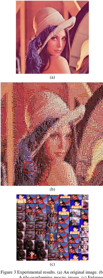
All the mosaic images of our experimental results were generated from the use of a tile image database with about 1900 images. Figure 3(a) is an input image.
Figure 3(b) is the resulting tile-overlapping mosaic image created from Figure 3(a) by applying Algorithm 1. Figure 3(c)is an enlarged image composed of several tile images enclosed by the red region shown in Figure 3(b).
3. PROPOSED METHOD FOR DATA HIDING IN TILE-OVERLAPPING MOSAIC IMAGES
In Section 3.1, the idea of the proposed data hiding and extraction methods will be introduced. And in Sections 3.2 and 3.3, the proposed detailed data hiding and extraction algorithms will be described.
3.1. Concept of Proposed Method
The main concept of the proposed data hiding method in a tile-overlapping mosaic image is to utilize the overlapping degree of every pair of adjacent tile images as a secret data embedding location. More specifically, we derive a randomized bit sequence from the input secret message using a secret key, and then embed every 3-bit data of the bit sequence in order into the tile-overlapping mosaic image created from a given image to obtain a stego-tile overlapping mosaic image.
The embedding work is done during the mosaic image creation process.
The data extraction process is an inverse version of the hiding process. We extract the value of the overlapping degree between each pair of adjacent tile images in a stego-tile-overlapping mosaic image and apply a data recovery process to obtain the hidden bit sequence. The details are described in the following.
3.2. Proposed Data Hiding Process
Before data hiding in a tile-overlapping mosaic image, we process the input image in advance. If the RGB values of a pixel in the image are (0, 0, 0) or (1, 1, 1), we replace them with the RGB values (0, 0, 1); the two colors (0, 0, 0) and (1, 1, 1) are reserved specially for use in the data extraction process.
The data hiding process essentially is to take in order 3-bit sequences from the prefix of a randomized version of the secret message as overlapping degree values and run Algorithm 1 to embed them into the created tile-overlapping mosaic image.
In case a hole is created using a certain overlapping degree, we have to eliminate the hole by adjusting the horizontal or vertical position of the tile with respect to its left or upper tile image, respectively, as mentioned previously. But then the overlapping degree is changed, meaning that the originally embedded 3-bit sequence is changed such that the embedding must be abandoned. This says equivalently that if we have to adjust the position of some tile image in one direction (horizontal or vertical) to avoid creating a hole, the overlapping in this direction should not be used to hide secret data anymore. In such a case, the overlapping on the other direction is tried, or the next tile image should be used if the overlappings of both directions are unusable.
In addition, data extraction to be described later is conducted in a raster scan order; the tile image, denoted by RT, to the right of the currently-processed one, denoted by CT, will be the next to be processed for data extraction. We access RT along a line drawn from the center of CT to the right. Therefore, to assure the accessibility of RT in this way, we limit the center of RT to be located within a range RA (e.g., −3 pixels to +10 pixels for 32×32 tile images in this study) with respect to the center of CT both in the horizontal and in the vertical directions. Furthermore, similar to the case of hole elimination, when the position of RT is adjusted in (a)
(b)
(c)
Figure 3 Experimental results. (a) An original image. (b) A tile-overlapping mosaic image. (c) Enlarged image part of red region in (b).
either the horizontal or the vertical direction due to this range limitation, it means that the overlapping in that direction cannot be used for data embedding.
When the position of RT needs to be adjusted due to hole elimination or/and RT accessibility as mentioned above, we say that the position is illegal. We move repetitively an RT with an illegal position horizontally or/and vertically for a random distance in the range RA mentioned above as done in Algorithm 1. The random distance is generated by a random number generator.
Note that both hole elimination and RT accessibility must be accomplished, when necessary.
Furthermore, if secret data cannot be embedded in the horizontal (or vertical) direction, we draw as a mark the left and right (or upper and lower) borders with the color value of (1, 1, 1). Contrastively, for those overlappings into which secret data are embedded, the respective borders are drawn with the color value of (0, 0, 0). In this way, by detecting the color of a tile image border, we know whether a 3-bit sequence is hidden in the tile image or not. The detail of the data hiding process is described as an algorithm in the following.
Algorithm 2: Data hiding in a tile-overlapping mosaic image.
Input: a cover image I, a secret message Mes, a secret key K and a similarity measure SM.
Output: a stego-tile-overlapping mosaic image S.
Steps:
Step 1. Derive a random bit sequence DData from Mes and K by the following steps:
1.1. Use K to generate a random bit sequence Kseq with its length equal to that of Mes.
1.2. Perform the bitwise exclusive-OR operation to Kseq and Mes to generate a third bit sequence KM.
1.3. Append an end signal of 16 consecutive bits of 0’s to the end of KM and take the result as the desired sequence of DData.
Step 2. Embed bits of DData sequentially into the first column of S by performing Step 1 of Algorithm 1 except in Step 1.4, instead of generating the integer RN by a random number generator, take sequentially 3 bits from the prefix of DData and transform them into an integer for use as the RN in performing the step.
Step 3. Embed the leading remaining bits of DData into the first row of S in a way similar to the previous step.
Step 4. Embed the remaining bits of DData in order into the inner tile images of S in a raster scan order in the following way.
4.1. Try to embed 3-bit data into the horizontal overlapping of the target image Tarij in the following way.
4.1.1 Take 3 bits from the prefix of DData, transform them into an integer number RN1, and create another integer number RN2 = 0.
4.1.2 Derive the horizontal and vertical positions of Tarij by running Step 3.2 of Algorithm 1 with RN1 and RN2 as input.
4.1.3 Check if the horizontal position of Tarij is legal or not. If legal, go to Step 4.3;
otherwise, continue.
4.1.4 Change the position of Tarij by moving it to the left or right until the horizontal position of Tarij becomes legal (with the horizontal overlapping abandoned for data embedding).
4.2. Try to embed 3-bit data represented by RN1
into the vertical overlapping of Tarij in the following way.
4.2.1 Move Tarij upward with RN1 pixels (with the intention to embed the 3 bits forming RN1 into the vertical overlapping), and check if the vertical position of Tarij is legal or not. If legal, go to Step 4.4;
otherwise, continue.
4.2.2 Change the position of Tarij by moving it upward or downward until the vertical position of Tarij becomes legal (with the vertical overlapping abandoned for data embedding), and transform RN1 back into the original 3-bit data and attach them back to DData as its prefix.
4.2.3 Go to Step 4.4.
4.3. Try to embed 3-bit data into the vertical overlapping of Tarij in the following way.
4.3.1 Take 3 bits from the prefix of DData and transform then into an integer number RN2.
4.3.2 Derive the position of Tarij by moving it upward for RN2 pixels.
4.3.3 Check if the vertical position of Tarij is legal or not. If legal, go to Step 4.4;
otherwise, continue.
4.3.4 Change the position of Tarij by moving it upward or downward until the vertical position of Tarij becomes legal (with the vertical overlapping abandoned for data embedding), and transform RN2 back into the original 3-bit data and attach them back to DData as its prefix.
4.4. Run Steps 3.4 and 3.5 of Algorithm 1 to create a best-matching tile image and draw it in S.
4.5. Repeat Steps 4.1 through 4.4 until all bits in DData are embedded.
Step 5. Run Step 3 of Algorithm 1 until all the remaining inner tile images of S are created (with no secret data embedded in the tile images created in this step).
3.3. Proposed Data Extraction Process
The main concept of the data extraction process is to figure out the horizontal and vertical overlappings of the tile images in a stego-tile-overlapping mosaic image
and extract the secret bits represented by the overlapping degree values. Because we replace pixel color values (0, 0, 0) and (1, 1, 1) with the value (0, 0, 1) in advance, there will be no pixel with values (0, 0, 0) or (1, 1, 1) except on the borders. We judge whether a bit is hidden or not by two colors of these borders. After the extraction process, we get the randomized bit sequence DData from which we can recover the embedded message using the original secret key K. The detail of the data extraction process is described as an algorithm as follows.
Algorithm 3: data extraction process.
Input: a stego-tile-overlapping mosaic image S and a secret key K.
Output: a secret message Mes.
Steps:
Step 1. Find the vertical overlappings of the tile images in the first column of S by the following way.
1.1. From the center of T0j, scan downward pixel by pixel until meeting a pixel P with color values (0, 0, 0) or (1, 1, 1).
1.2. Derive the overlapping degree value O by subtracting the vertical position of P from that of the lower border of T0j.
1.3. Transform O to into a 3-bit sequence.
1.4. Repeat Steps 1.1 through 1.3 until the entire first column of S are processed.
Step 2. Process the first row in a similar way to the last step to derive the horizontal overlapping values and their corresponding 3-bit sequences.
Step 3. Find the horizontal and vertical overlappings of the inner tiles in a similar way to the last two steps.
Step 4. Concatenate all the extracted 3-bit sequences in order into a longer sequence, search in it to find the end signal composed of 16 consecutive bits of 0’s, and truncate them and the bits after them to form a bit sequence DData.
Step 5. Generate a random bit sequence Kseq using the secret key K as an input to run the random number generator F identical to that used in Algorithm 2, perform the exclusive-OR operation to DData and Kseq, and take the result as the desired secret message Mes.
4. EXPERIMENTAL RESULTS
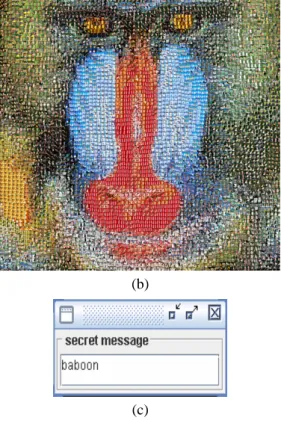
Figure 4 shows some experimental results of the proposed data hiding in a tile-overlapping mosaic image.
Figure 4(a) is an original image. Figure 4(b) is a tile- overlapping mosaic image with the secret message,
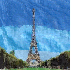
“baboon,” embedded. Figure 4(c) is the secret message extracted from Figure 4(b) with a correct key. Figure 4(d) shows the secret message extracted from Figure 4(b) with a wrong key. Figure 5 shows another experimental result. From these results, we see that the hidden message is unnoticeable to an observer, and so the proposed method is effective.
5. CONCLUSIONS
Methods for tile-overlapping mosaic image creation and data hiding have been proposed, which are based on the use of horizontal and vertical tile image overlappings tile images. The created new-style mosaic image is more vivid in appearance. Data hiding in such mosaic images has the effect of steganography. The problem of hole creation has been solved. Algorithms for data hiding and extractions have also been proposed.
Good experimental results show the effectiveness of the proposed methods. The proposed data hiding methods may be used for various applications, such covert communication, copyright protection, etc. There are still some interesting topics which are worth further studies.
For example, we can produce mosaic images with other shapes and select appropriate image features to achieve corresponding data hiding works.
REFERENCES
[1] Y. W. Guo, J. H. Yu, X. D. Xu, and Q. S. Peng,
“Example based painting generation,” Journal of Zhejiang University: Science, Vol 7, No 7, pp.
1152-1159, July 2006.
[2] G. C. Chen, “Automatic generation of pencil sketching with the effects of paper texture,” M. S.
Thesis, Department of Computer and Information Science, National Chiao Tung University, Hsinchu, Taiwan, Republic of China, June 2006.
[3] B. Baxter, V. Scheib, M. C. Lin, and D. Manocha,
“DAB: interactive haptic painting with 3D virtual brushes,” Proceedings of. SIGGRAPH 01, pp. 461- 468, Aug. 2001.
[4] Von Laerhoven, Tom and Van Reeth, Frank, “Real- time simulation of watery paint,” Computer Animation and Virtual Worlds, Vol 16, No 3-4, pp.
429-439, July 2005.
[5] A. Hertzmann, “Painterly rendering with curved brush strokes of multiple sizes,” Proceedings of SIGGRAPH 98, pp. 453-460, Orlando, Florida, USA, July 1998.
[6] C. J. Curtis, S. E. Anderson, J. E. Seims, K. W.
Fleischer, and D. H. Salesin, “Computer-generated watercolor,” Proceedings of SIGGRAPH 97, pp.
421-430, Los Angeles, California, USA, August 1997.
[7] U. N. Chen, “Non-photorealistic 3D rendering in Chinese painting style,” M. S. Thesis, Department of Computer Science and Information Engineering, National Cheng Kung University, Tainan, Taiwan, Republic of China, July 2003.
[8] K Kojima, S Takahashi, T Nishita, “Creating quadrilateral mosaics from image topographic features,” Proceedings of the 3rd symposium on Applied perception in graphics and visualization, 2006.
[9] Paul E. Haeberli, “Paint by numbers: abstract image representations,” Proceedings of SIGGRAPH 90, pp. 207-214, August 1990.
[10] Alejo Hausner, “Simulating decorative mosaics,”
Proceedings of SIGGRAPH 01, pp. 573-580, New York, USA, 2001.
[11] Hoff, K., Keyser, J., Lin, M., Manocha, D. and Culver, T. “Fast computation of generalized voronoi diagrams using graphics hardware,”
Proceedings of SIGGRAPH 99, pp. 277-286, August 1999.
[12] S. P. Lloyd, “Least square quantization in PCM,”
IEEE Transactions on Information Theory, vol. IT- 28, no. 2, pp. 129-137,March 1982.
[13] D. C. Wu and W. H. Tsai, “A steganographic method for images by pixel-value differencing,”
Pattern Recognition Letters, Vol. 24, No. 9-10, pp.
1623-1636, 2003.
[14] Y. C. Chiu and W. H. Tsai, “Copyright protection by watermarking for Color Images against Rotation and Scaling Attacks Using Peak Detection and Synchronization in Discrete Fourier Transform Domain,” Proceedings of Third Workshop on Digital Archives Technologies, pp. 207-213, Taipei, Taiwan, August 5-6, 2004
[15] W. L. Lin and W. H. Tsai, “Data hiding in image mosaics by visible boundary regions and its copyright protection application against print-and- scan attacks,” Proceedings of 2004 International Computer Symposium (ICS 2004), Taipei, Taiwan, Dec. 2004.
[16] S. C. Hung, T. Y. Liu and W. H. Tsai, “A new approach to automatic generation of tile mosaic images for data hiding applications,” Proceedings of 2005 Conference on Digital Contents Management & Applications (DCMA 2005), pp.
11-20, Kaohsiung, Taiwan, June 2005.
[17] C. Y. Hsu and W. H. Tsai, “Creation of a new type of image - circular dotted image - for data hiding by a dot overlapping scheme,” Proceedings of 19th Conference on Computer Vision, Graphics and Image Processing, Taoyuan, Taiwan, August 2006.
(a)
(b)
(c)
(d)
Figure 4 An experimental result of data hiding in a tile- overlapping mosaic image. (a) Original image.
(b) Tile-overlapping mosaic image with a secret message “baboon” embedded (c) Secret message extracted from (b) with a correct key.
(d) Secret message extracted from (b) with a wrong key.
(a)
(b)
(c)
(d)
Figure 5 Another experimental result of data hiding in a tile-overlapping mosaic image. (a) Original image. (b) Tile-overlapping mosaic image with a secret message embedded. (c) Secret message extracted from (b) with a correct key. (d) Secret message extracted from (b) with a wrong key.
![Figure 1 A flowchart of adopted mosaic image creation method [15].](https://thumb-ap.123doks.com/thumbv2/9libinfo/9503044.596470/2.892.469.776.311.847/figure-flowchart-adopted-mosaic-image-creation-method.webp)