IOP Conference Series: Materials Science and Engineering
PAPER • OPEN ACCESS
A case study of urban road subsidence induced by the underground connection of the shield tunnelling method
To cite this article: Y H Chen and H H Pan 2019 IOP Conf. Ser.: Mater. Sci. Eng. 615 012025
View the article online for updates and enhancements.
This content was downloaded from IP address 140.127.116.32 on 17/10/2019 at 09:15
7th International Conference on Euro Asia Civil Engineering Forum IOP Conf. Series: Materials Science and Engineering 615 (2019) 012025
IOP Publishing doi:10.1088/1757-899X/615/1/012025
A case study of urban road subsidence induced by the underground connection of the shield tunnelling method
Y H Chen
1and H H Pan
2,31
Engineering Coordinator, Southern Engineering Center-Taiwan Power Dalin Department, Sinotech Engineering Consultants, Kaohsiung 812, Taiwan
2
Professor, Department of Civil Engineering, Kaohsiung University of Science and Technology, Kaohsiung 807, Taiwan
3
E-mail: pam@nkust.edu.tw
Abstract. A case study of the road subsidence hazard that occurred during the construction of a cable tunnel was conducted. The cable tunnel was built 30 m below the ground surface by using the shield tunnelling method, parallel to a sewage pipe with a diameter of 2000 mm.
During shield docking, the bolt of the seal plate in the shield segment ruptured. This rupture led to water flooding into tunnel and the settlement of the ground surface. The causes of the subsidence hazard were analysed and discussed. The results of this case study indicate that risk assessment and hazard analysis of shield tunnels should be conducted separately in the planning, design, and construction phases for ensuring disaster mitigation. To avoid the occurrence of a subsidence hazard, sensors should be embedded 30 m below the ground surface and near the shield machine. Using monitoring sensors and increasing the number of observed frequency are effective in enhancing the settlement sensitivity so as to provide early warning information. Ground improvement is suggested even while using the concentric interlace docking method.
1. Introduction
When sewers, pipelines, and subways are constructed in the urban region by using the shield tunneling methods, the amount of traffic congestion and air pollution is low. However, occasional hazards, such as the ones that occurred in Japan [1], China [2], and Taiwan [3], induce a large area of ground subsidence due to the construction of a shield tunnel, thus damaging facilities and causing the loss of life. Many effects may induce the hazard of ground subsidence. Here, a case study of the hazard of road surface subsidence that was caused by leaking at a docking tunnel during the construction of cable tunnel was investigated. The cable tunnel located in Kaohsiung, Taiwan, was built 30 m below the ground surface by using the shield tunneling method. The diameter and the length of the designed shield tunnel were 5.7 m and 5344 m, respectively. Moreover, an existing sewage pipe with a diameter of 2000 mm was parallel to and 15 m above the designed cable tunnel.
2. Construction description
The cable tunnel was designed for using a 345 kV cable that started from the Daling G/S thermal
power plant and ended at the Gaogong P/S primary substation in Kaohsiung. The construction zone
comprises sandy soil. The specifications of the shield tunneling machine were applicable to the earth
7th International Conference on Euro Asia Civil Engineering Forum IOP Conf. Series: Materials Science and Engineering 615 (2019) 012025
IOP Publishing doi:10.1088/1757-899X/615/1/012025
2
pressure balance shield method, and the drilling rate of the shield was approximately 12 m every day.
Two shield boring machines were used to construct the shield tunnel and to separately move forward at shaft #1 and shaft #2 that were located at both sides of the cable tunnel. The machines were connected by the concentric interlace docking (CID) method at a distance of 3k + 060 m. The CID method uses two special shields to connect the machines to each other without using any additional site improvement. The details of the construction are described in previous studies [4, 5]
To reduce the risk of hazards during the construction, the main sub-divisional tasks, such as conducting quick segment joining, high-speed moving shield operation, CID use, and underground pipeline protection steps, underwent a qualitative risk analysis in this project. After the preliminary stage of hazard analysis of shield tunneling, emergency response strategy and disaster prevention drill were also planned in the construction plan. During the construction, several sensors along the construction route were installed 2 − 3 m below the ground surface for subsidence monitoring.
3. Course of the accident
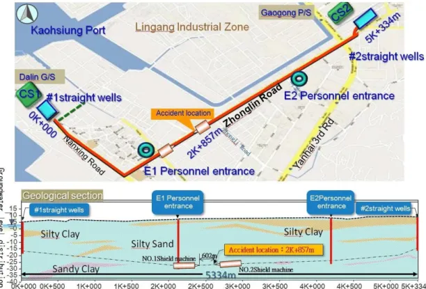
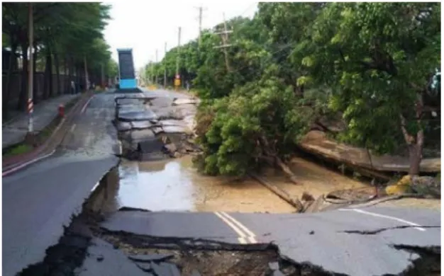
When head #2 of the shield boring machines reached the docking tunnel position with a digging length of 2477 m, the driving length of head #1 in the shield tunnel was 2255 m. At this point, head #1 was 602 m away from head #2 of the shield boring machines. In the early morning of September 18, 2015, the accident of inducing subsurface settlement occurred at a distance of 2k + 857 m, as shown in figure 1. The settlement trough was approximately 100 m long, 15 m wide, and 30 m deep and caused the road and warehouse subsidence displayed in figures 2 and 3, respectively. The subsidence hazards incurred road subsidence, pipeline damage, and warehouse damage. The subsurface settlement was caused because there was an unexpected water pressure at head #2 of the shield boring machines when the outer shield moved out. This pressure caused the bolts of the water stop plate to be broken on September 17, thus causing the tunnel to be flooded with water and soil. By following the emergency response guidelines, the construction contractor used stow-wood and cloth to block the flowing water and soil, injected grease into the shaft seal, and used quick-drying cement as filling material to stop the leakage.
Figure 1. Plan illustration and stratigraphic section of the accident location.
7th International Conference on Euro Asia Civil Engineering Forum IOP Conf. Series: Materials Science and Engineering 615 (2019) 012025
IOP Publishing doi:10.1088/1757-899X/615/1/012025
Figure 2. Road subsidence due to subsurface
settlement. Figure 3. Warehouse subsidence due to
subsurface settlement.
However, mass water and soil continued to flood into the tunnel. Additional emergency measures were taken: 1) sandbags were stacked to stop the water inrush, shown in figure 4, and 2) the hydraulic jacks applied loads to slow down slurry. As large quantity of water gushed out, the local soil under the front shield hollowed. This effect caused the head of shield machine to have a 200 mm subsidence.
Then, the back of the connecting shield segment was dragged and began to deform, thus inducing a successive water leakage near the segment joints.
Figure 4. Stacking sandbags to stop water inrush in the tunnel.
Due to the sinking of the shield machine into the ground and the compression of the upper soil layer, the deformation of shield segments continued to increase, and a higher amount of slurry flooded into the tunnel. As the shield segments began to slump, all workers had to be evacuated to the ground.
The land subsidence hazard on the ground was observed 24 h after the unexpected water flooding into
the tunnel. Moreover, as no early warning signals were detected from the monitoring sensors installed
by the construction contractor along the construction route, the land subsidence fractured two water
pipes (400 and 600 mm in diameter) near the construction site. Large quantities of water gushed into
the soil layer and flowed on the ground at least for 3 h, which led to increase in the land subsidence.
7th International Conference on Euro Asia Civil Engineering Forum IOP Conf. Series: Materials Science and Engineering 615 (2019) 012025
IOP Publishing doi:10.1088/1757-899X/615/1/012025
4
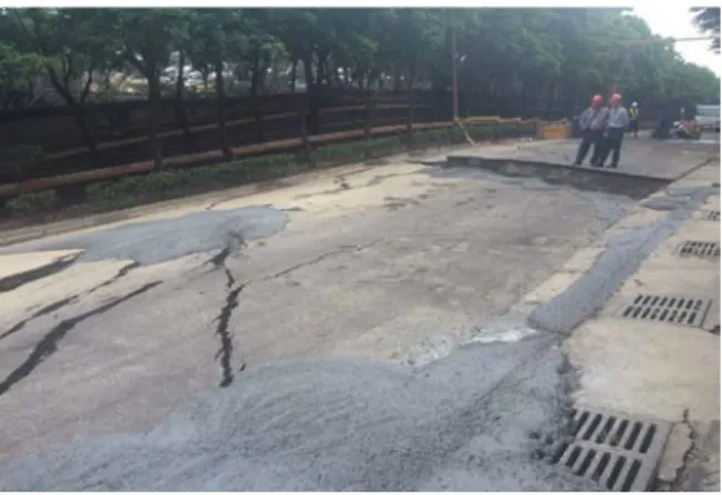
The land subsidence hazard caused a 10-m long and 75-m wide road collapse. Many factory buildings tilted due to the occurrence of alligator cracking on the road, as shown in figures 5 and 6. Moreover, underground pipelines, including telecommunications line, power line, water pipe, sewage pipe, oil pipes, and gas pipes, were damaged. The hazard influenced 4000 power users and 300 water users, and the total loss based on the preliminary estimate was approximately 17 million US dollars.
During the period of recovery rescue, aerial photography was used twice a day to manage the hazard-impacted area, and 36 monitoring points were installed at the warehouse of China Steel Corporation (CSC) and Chinese Petroleum Corporation (CPC) near the hazard zone to monitor the change in land subsidence every 2–4 h, as shown in figures 7 and 8.
Figure 5. The CPC warehouse subsided due to
the land subsidence hazard. Figure 6. Alligator cracking of the road that occurred due to the land subsidence hazard.
Figure 7. Aerial photo of the hazard-impacted
area of the disaster. Figure 8. Hazard-impacted area and 36 monitoring points nearby, which include 14 points at the CSC warehouse and 22 points at the CPC warehouse.
4. Cause analysis of hazard
In this case, the direct cause for the land subsidence hazard was water influx into the tunnel that caused the settlement of head #2 of the shield machine and soil loss in the upper soil layer.
Simultaneously, large quantities of water gushed out from two broken water pipes that extended the
area of the settlement trough. The soil sank due to the water influx, thus causing the head #2 of the
shield machine to deform. This led to a higher amount of leakage in the shield segment connection and
caused the tunnel segments to collapse finally.
7th International Conference on Euro Asia Civil Engineering Forum IOP Conf. Series: Materials Science and Engineering 615 (2019) 012025
IOP Publishing doi:10.1088/1757-899X/615/1/012025
The indirect cause of the hazard was that the bolts of the water stop plate ruptured while the front shield was moving ahead out from head #2 of the shield machine. Thus, the water seal between the front shield and head #2 of the shield machine tore and was pushed away to its original position.
Unexpected extra loads that exceeded the strength of the bolds were not considered in the structural calculation of the shield tunneling method. The other indirect cause of hazard was that no soil improvement works were conducted for the soil near the junction at which the CID method was conducted. Thus, a higher amount of ground water and slurry flowed into the tunnel. To reduce the risk of subsidence, suitable ground improvement works are required even while conducting the CID method
Moreover, in this case, the sensors for subsidence monitoring were installed 2 − 3 m below the ground surface because there were many pipelines along the construction route. Thus, the monitoring sensors were not installed in the deep soil layer to avoid any harm to the pipes. Only the surface subsidence data in the neighboring area of the accident location (2k + 857 m) were recorded.
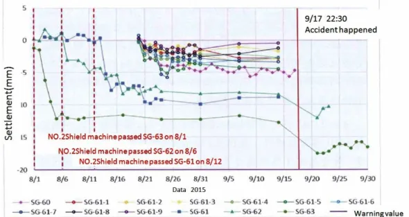
Figure 9 presents the records of the subsidence near the accident location and 2.2 m below the ground surface during August and September, 2015. Head #2 of the shield machine passed through the settlement monitoring points SG-63, SG-62, and SG-61 on August 1, August 6, and August 12, respectively. Obvious settlements were observed on August 2−5 (at SG-63), 7 (at SG-62) and 13−15 (at SG-61) respectively when head #2 of the shield machine passed through the settlement monitoring points, as shown in figure 9. The settlement of monitoring points at SG-61 and SG-60-1 to SG-60-9 were recorded manually and the last monitoring data were recorded the day before the occurrence of the accident, that is, on September 15. Figure 9 indicates that the maximum settlement value was approximately -10 mm, and all the monitoring values were lower than the warning value of -20 mm.
All observed monitoring data of subsidence were normal (less than the warning value) on September 15. This implies that the surface subsidence data showed no abnormal subsidence until the hazard occurred. No subsidence warning signal was provided by the sensors before the hazard because the sensors were embedded 2−3 m below the ground surface and were not 30 m below the ground surface, that is, near head #2 of the shield machine. Therefore, the monitoring sensors were located near the ground surface and far away from the construction site. Thus, they could not present any deep subsidence data which we needed.
Figure 9. Subsidence data acquired by the monitoring sensor embedded in 2.2 m below the ground
surface, near the accident location.
7th International Conference on Euro Asia Civil Engineering Forum IOP Conf. Series: Materials Science and Engineering 615 (2019) 012025
IOP Publishing doi:10.1088/1757-899X/615/1/012025
6