國立臺灣大學工學院機械工程學系 碩士論文
Department of Mechanical Engineering College of Engineering
National Taiwan University Master Thesis
下半身輔具及防跌倒機構之設計
Design of walking-assistive device on lower limb with fall- preventing mechanism
許恒嘉 Heng-Chia HSU
指導教授:施文彬 博士 Advisor: Wen-Pin Shih, Ph.D.
中華民國 104 年 10 月
October, 2015
誌謝
時間過得很快,在這一段碩士班學習的過程中,得到了很多人的幫助,非常誠 摯的感謝大家。
首先,要謝謝指導教授施文彬老師,感謝老師不僅在研究上專業知識,更加在 學習以及做事的態度上給予指導,謝謝郭進星教授,給予我在機構上的建議以及改 善的方法,讓我可以完成論文的機構設計,也要感謝口試委員,張培仁教授、胡毓 忠教授給予我論文建議以及不足之處的指導,使我的論文可以更加完善。
感謝 TiMMeL 實驗室的大家: 梁道、承俊、品淳、鐸儒、宥延、瑜瑄、啟雲、
哲銘、益隆、期宇、淳右、柏安、紹傑、俞齊、瑋杰、彥安、胤禎,和 Mandy 等 實驗室的學長以及同學們的陪伴,給予我的碩士生涯中給予許多建議與幫助。也要 感謝我的好朋友們,中興生機系 102 的朋友們,在研究生涯的生活中,互相的打氣 以及給予建議,讓我能更加有信心的走下去。
也感謝我的家人,謝謝你們給予我支持以及鼓勵,讓我可以無後顧之憂得完成 我的碩士學位。
許恒嘉 October 2015
中文摘要
近年來,高齡化的現象越來越明顯,年長者的比例大幅度的上升,而防止老人跌 倒的問題就成了一個很大的議題,在年長者中有將近三分之一的人曾發生過跌倒,
然而,這情況發生後發生第二次跌倒的機會更大,在第一次跌倒後,需要耗費大量 的人力以及社會成本來照顧以及避免再次的跌倒。人們常說預防勝於治療,本論文 希望可以藉由下半身外骨骼輔具的機構設計,在特定的步態下,將小腿以及大腿的 相對轉動固定,期望能夠達到防止跌倒的功能,藉此減少因老人跌倒而造成的人力 及社會成本。
首先,為了不讓老人穿上下半身外骨骼後,反而造成其身體不方便,所以,我們 希望外骨骼的機構可以很適合人體,我們探討下半身的兩的關節,膝蓋關節以及髖 關節,膝蓋關節是一個鉸鏈關節,除了轉動以外,膝蓋關節還有滑動的動作,然而,
膝蓋是一個包括前後十字韌帶以及多條肌肉連動所形成的結構,為了避免下肢外 骨骼輔具設計太過複雜以及過於笨重,膝蓋的部份我們將其簡化成只有鉸鏈關節。
然而,不同於其他的下肢輔具,我們希望可以把原有大部分下肢輔具中,膝蓋關節 部分的馬達用簡單機構的方式取代,以此降低整體輔具的重量。然後,髖關節的部 分是球窩關節,擁有屈伸以及內收外展的自由度,但其轉動軸心在身體內部,以穿 著在外的輔具來說,則是將兩個自由度分別拆開,並且將兩個自由旋轉軸心交於髖 關節的球窩中心,以此達到類似髖關節的運動方式,而髖關節的部分,雖然有兩個 自由度,我們只考慮使用馬達控制屈伸的自由度,以此來抬起外骨骼輔具,至於內 收外展的自由度,目的是為了使穿戴著不會因此外骨骼而限制其原本習慣的走路 狀態,所以將其變成被動的轉軸,當行走的時候他會隨者人而自己轉動。
再來,我們有了外骨骼的雛形後,再分析步態的細節,找出可以防止跌倒的可能 性,我們在小腿及大腿發生相對轉動的膝蓋上,設計出一個滑軌以及滑塊的機構,
藉此可以達到在單腳站立的步態時,限制膝蓋關節的轉動,達到固定且防止跌倒的 效果,但這個固定卻不會使腳在擺動步態的狀態時,限制住大腿及小腿的相對運動,
換言之,藉由此機構,達到需要固定時固定之,需要使膝蓋關節轉動時,讓它轉動。
最後藉由向量迴路法,分析出適合的尺寸及大小,並且先以木頭製造出簡單的模 型,再將此模型大幅度縮小及美化,製造出最後的模型。實驗部分,希望可以由外
骨骼的角度變化,配對其正常人的角度變化,看是否此外骨骼的設計可以貼近實際 人類的行走狀態。而在於防跌倒機構的部份,可知機構已達到我們期望的效果,但 是至於此效果可否達到防止跌倒的功能是否,目前還沒找到驗證的方法,未來會尋 找一個適合驗證的方案。
關鍵字:外骨骼;步態分析;防止跌倒
ABSTRACT
The population of the elders has dramatically increased, and fall prevention has become an important issue for elders care. This paper attempts to design a lower-limb exoskeleton, which could fix the relative rotation of the thigh and calf at specific gait to make the function of fall prevention and helping elder’s walk. Unlike other assist devices, we replace the motor by special mechanism at knee joint for reducing the weight and making control easier on the device. We separate hip joint into two axes (rotation of flexion/extension and adduction/abduction) on the assistive device and make these two axes intersect at the center of the hip joint. Therefore, we can make the joint on the assistive device similar to hip joint. Based on human gait, we design a slider mechanism on the knee part that could be fixed for the leg at its state. Finally, we optimize the design and test a metal prototype. Through experiments, we measure the rotation about hip and knee to verify the function of our assistive device. About the fall-preventing mechanism, we can know the mechanism can reach our purpose, but we don’t know whether this method can reach fall-preventing. In future, we will find some methods to prove the fall- preventing.
Keywords: exoskeleton; gait analysis; prevent of falls
SYMBOL TABLE
r
1 Length between hip joint to knee jointr
2 Length between the rotation center of knee to the slider centerr
3 Change of the slider movement in the sliding groover
4 Length of the fixed barr
5 Length from motor shaft to the center of the fixed end
1 Angle between 𝑟1 and level line.
2 Angle between 𝑟2 and level line.
3 Angle between 𝑟3 and level line.
4 Angle between 𝑟4 and level line.
5 Angle between 𝑟5 and level line.
Rotation degree of hip joint
Rotation degree of knee jointCONTENTS
口試委員會審定書 ... #
誌謝 ... i
中文摘要 ... ii
ABSTRACT ... iv
SYMBOL TABLE ... v
CONTENTS ... vi
LIST OF FIGURES ... viii
LIST OF TABLES ... x
Chapter 1 Introduction ... 1
1.1 Background ... 1
1.2 Overview of walking assist device ... 3
1.2.1 Exoskeleton of enhancement ... 4
1.2.2 Exoskeleton of assist ... 7
Chapter 2 Walking assist device design ... 14
2.1 Design target ... 14
2.1.1 Lower limb joints ... 14
2.1.2 Gait analysis ... 18
2.1.3 Design target ... 22
2.2 Device detail ... 25
2.3 Preventing falling mechanism ... 31
2.4 Mechanism model ... 34
2.4.1 Mechanism model ... 34
2.4.2 Dimension and restriction of the assist device ... 39
Chapter 3 Simulation of device ... 43
Chapter 4 Experiment process ... 51
4.1 Experiment instrument... 51
4.2 Experiment method ... 58
Chapter 5 Result and discussion ... 59
5.1 Moment of the assist device ... 59
5.2 Gait cycle of the assist device ... 62
Chapter 6 Conclusions and future works ... 70
REFERENCE ... 71
LIST OF FIGURES
Figure 1.1 Hardiman ... 3
Figure 1.2 Berkeley Lower Extremity Exoskeleton (BLEEX)……….6
Figure 1.3 (a) ExoHikerTM (b) ExoClimberTM (c) UCLCTM. ... 6
Figure 1.4 HONDA walking assist device... 8
Figure 1.5 HAL ... 10
Figure 1.6 REWALKTM ... 12
Figure 2.1 Illustration of the pelvic coordinate system (XYZ), femoral coordinate system (xyz), and the joint coordinate system for the right hip joint (𝑒1𝑒2𝑒3) ... 16
Figure 2.2 Motion of lower limb ... 17
Figure 2.3 Method of gait analysis ... 20
Figure 2.4 Mean (thick line) and one standard deviation (dotted lines) of hip and knee rotation ... 21
Figure 2.5 Gait cycle ... 24
Figure 2.6 Walking assist device ... 27
Figure 2.7 Component of assist device ... 28
Figure 2.8 Component of assist device ... 29
Figure 2.9 Component of assist device. ... 30
Figure 2.10 Preventing falling mechanism. ... 33
Figure 2.11 Side view of walking assist device ... 38
Figure 3.1 Simulation of assist device ... 44
Figure 3.2 Boundary condition and result of second and third gait ... 46
Figure 3.3 Boundary conditions of second gait ... 48
Figure 3.4 Results of second gait ... 49
Figure 3.5 Boundary conditions and results of third gait ... 50
Figure 4.1 Wood type assist device and CAD picture ... 53
Figure 4.2 Wood type of each component and CAD picture ... 54
Figure 4.3 Metal type assist device and CAD picture ... 56
Figure 4.4 Metal type of each component and CAD picture ... 57
Figure 5.1 Result of wood and metal type without tester ... 60
Figure 5.2 Result of wood and metal type with tester. ... 61
Figure 5.3 Gait cycle of the tester wear assist device ... 64
Figure 5.4 The mean and error bar compare with normal gait ... 65
Figure 5.5 Gait cycle of the tester wear assist device ... 66
Figure 5.6 The mean and error bar compare with normal gait ... 67
Figure 5.7 Gait cycle of the tester wear assist device ... 68
Figure 5.8 The mean and error bar compare with normal gait ... 69
LIST OF TABLES
Table 1-1 Risk factor of falling ... 2 Table 1-2 Detail of assist device in introduction ... 13 Table 3-1 Normalized mass of body segments (standard human) ... 47
Chapter 1 Introduction
1.1 Background 1.1 Background
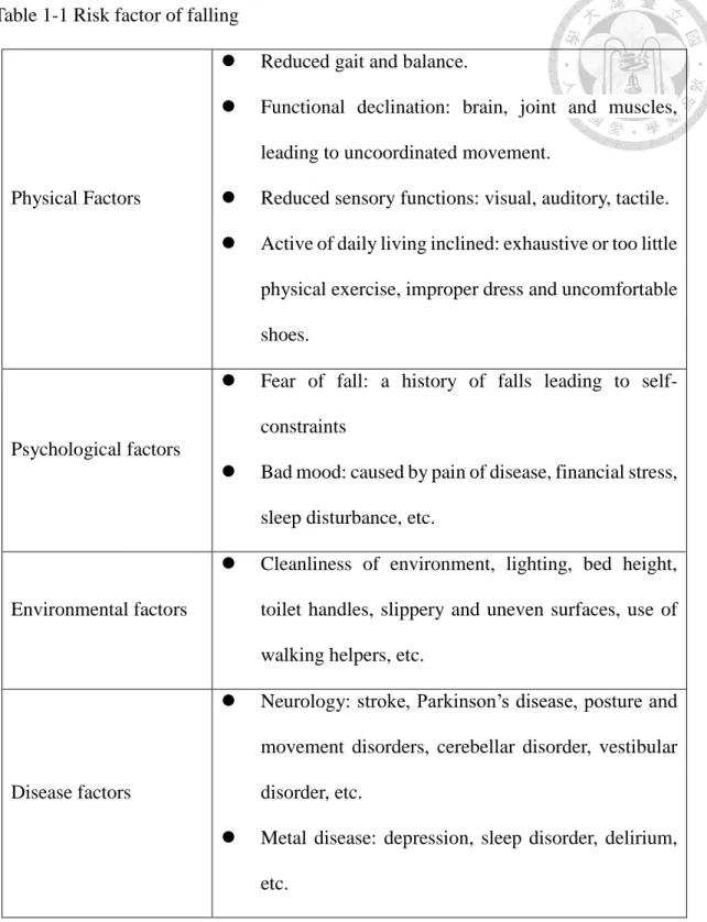
In recent years, the population of elders was greatly increasing day by day. The number of elderly people in the world has been consistently and proportionally increasing. In 2010, there were 440 million people in the world aged above 65 years in total [1], and will be forecasted to 1,555 million by 2050 [2] . Therefore, problems of the elderly care gradually show up. If the elderly have the ability to take care of themselves in their daily lives such as walking to toilet or taking a walk, the manpower to take care of the elderly can be reduced it also can solve the problem of care for the elderly. However, the falling issue of elders is a common and important problem. There would be more problems after the elders fell down. Therefore, preventing falling is an important issue. There are various risk factors which cause fallings of elders as listed in Table 1.1[3-8]
Many serious falls cause fractures and may lead to head injuries, depression, fear of recurrent falls, gait abnormality, sensor impairment, cognitive impairment, and social isolation. These may cause great social burden and make it more difficult to take care of the elderly. Most of the methods to prevent falling are in line with problems, such as treatment by medications, sort out the environment, etc. In addition to preventive measures above, rehabilitation gait training is a method, too. In this paper, we hope to design a mechanism to make the elderly walk normally and prevent falling in order to reach the ideal that the elderly can take care of themselves and walk safely.
Table 1-1 Risk factor of falling
Physical Factors
Reduced gait and balance.
Functional declination: brain, joint and muscles, leading to uncoordinated movement.
Reduced sensory functions: visual, auditory, tactile.
Active of daily living inclined: exhaustive or too little physical exercise, improper dress and uncomfortable shoes.
Psychological factors
Fear of fall: a history of falls leading to self- constraints
Bad mood: caused by pain of disease, financial stress, sleep disturbance, etc.
Environmental factors
Cleanliness of environment, lighting, bed height, toilet handles, slippery and uneven surfaces, use of walking helpers, etc.
Disease factors
Neurology: stroke, Parkinson’s disease, posture and movement disorders, cerebellar disorder, vestibular disorder, etc.
Metal disease: depression, sleep disorder, delirium, etc.
1.2 Overview of walking assist device
Walking assist device can be traced from the history of exoskeleton. Figure 1.1 shows the first set of exoskeleton –Hardiman, which was manufactured by GE in 1966 [9].
Exoskeleton is a multifunction assist device. According to different types, assist device has different benefits. Generally, the purpose of assist device can be divided into enhancement and assistance [10]. It can also be divided into four purposes for assistance, enhancement, protection, and detection [11]. The program of assistance enabled individuals with spinal cord injuries or handicapped to stand and walk again. Next the enhancement program improved the operator’s abilities, such as taking heavier objects, running faster or endurance augmentation. And the protection program had different protection functions which depended on the design of mechanism and material. It can also be used in the safety of nuclear power plant or protect the work during walking. As for the detection program, it obtained the information from human body with sensors.
The information was used to benefit rehabilitation and treatment. Moreover, the information can be used to control the exoskeleton. In the recent years, the researches of the exoskeleton are always combined with the application of above four purposes. So the exoskeleton can be divided into two categories, and described in the following article.
Figure 1.1 Hardiman
1.2.1 Exoskeleton of enhancement
In recent decades, the study of the exoskeleton had multiple functions, so it can be divided into two categories: enhancements, and assist. First, we introduce the enhancement type of exoskeleton.
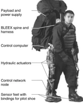
Figure 1.2 shows the exoskeleton BLEEX which is developed by Kazerooni and his research team in 2004 [12]. In order to conform to ergonomics, BLEEX comprises two powered anthropomorphic legs, a power supply and a backpack-like frame on which a variety of heavy payloads can be mounted. BLEEX also use a large number of sensors and hydraulic actuators. And the combination with inclinometer judging makes BLEEX be close to a human control system. In the other hand, BLEEX can reduce the wearer’s burden, wearer can walk without feeling any load at walking speed below 3.2 kilometers per hour.
Next, Kazerooni and his research team strengthened the capacity of their exoskeleton.
Figure 1.3(a) shows ExoHikerTM [13] which was completed in February 2005. With the weight of 14kg including power unit, batteries and on-board computer, ExoHikerTM can make the wearer feel no load with 70 kg mounted. Compared with BLEEX, ExoHikerTM increased the loads and reduced the weight. It also had a solar panel and an 80 W-hour battery so that ExoHikerTM can carry heavy loads during long mission. Generally speaking, ExoHikerTM can carry 70 kg for 21 hours while the wearer feels no load on his shoulder. In the same year, ExoClimberTM [14] retained the same long term load carrying capability of ExoHiker™, as shown in Figure 1.3(b). Although its weight was 22 kg, it was design to allow rapid stair ascent. The mission range possesses at least 200 mm ascent per 500g of battery while carrying 70kg payload. Without a doubt, ExoClimberTM can also carry 70 kg of load as the wearer feeling no load on his shoulder. Figure 1.3(c) shows UCLCTM(Human Universal Load Carrier)which was combined with ExoHiker™ and
ExoClimberTM. UCLCTM enhanced the capacity, it can carry 90 kg. In particular, the oxygen consumption of these users carrying a 36 kg approach load at a speed of 3.2 km per hour decreased by about 15% when using the prototype HULC™. The function of reducing burden on the user is a great development, reducing burden for long-term task is very important for soldiers [15].
(c)
(a) (b)Figure 1.3 (a) ExoHikerTM [14]. (b) ExoClimberTM [15]. (c) UCLCTM [16].
Figure 1.2 Berkeley Lower Extremity Exoskeleton (BLEEX)
1.2.2 Exoskeleton of assist
Then, we introduce the assist type of exoskeleton. In this paper, our purpose is to design a lower limb assist device, the purpose of our assist device is similar to this type of exoskeleton. There are many functions in assist exoskeleton. For example, Honda developed the Walking Assist Device programs [16,17], University of Tsukuba developed Hybrid Assistive Limb [18], and Argo Medical Technologies developed the ReWalk which was the only exoskeleton system passed FDA (Food and Drug Administration).
Figure 1.4 shows the appearances of Honda’s Walking Assist Device. Honda didn’t call the device “exoskeleton,” they called it walking assist device since the purpose of this programs are assisting in walking not like armor wear on body. Figure 1.4(a) shows Walking Assist Device with Stride Management Assist (WADSM) which is a lightweight (about 2.8kg with battery), simple design with a belt worn around the hips and thighs was created to reduce the wearer’s load and to fit different body shapes. Figure 1.4(b) shows the patent of WADSM which has a special mechanism shown as Fig 1.4(c). Because of the special mechanism, the thigh can be lifted easily. Figure 1.4(d) shows the Honda’s second walking assist device - Walking Assist Device with Bodyweight Support Assist (WADBSA). It helps support bodyweight to reduce the load on the user's legs while walking, going up and down stairs, and in a semi-crouching position. This could lead to reduced fatigue and less physical exertion. Figure 1.4(e) shows the patent of this device.
Although this device is heavier than the first one, it has a very special design. Different from other exoskeleton which are worn on thigh or knee, the device is only worn on shoes as shown in Figure 1.4(e). There exists a place to be seat on and it has force sensors on feet. With the computer and sensors, the device can get specific information to control and drive the motor.
(a) (b)
(c) (d) (e)
Figure 1.4 HONDA walking assist device (a) Walking Assist Device with Stride Management Assist [17]. (b) Patent of Walking Assist Device with Stride Management Assist [17]. (c) Special mechanism of Walking Assist Device with Stride Management Assist. (d) Walking Assist Device with Bodyweight Support Assist [18]. (e) Patent of Walking Assist Device
Yoshiyuki Sankai and his research team developed the first HAL (Hybrid Assistive Limb) prototype in 1990. The third HAL prototype, developed in the early 2000s, was attached to a computer. Its battery weighed nearly 22 kg and required two helpers to put on, making it very impractical. By contrast, later HAL-5 model weighs only 10 kilograms and wears more conveniently [19]. Figure 1.5(a) shows HAL-5 which is divided into upper and lower limbs. HAL-5 consists of controller/computer, battery, myoelectricity sensors, angle sensors, force sensors, floor reaction force sensors (COP/COG sensors), etc. [20]. As shown in Fig 1.5(b), the patent of HAL-5 lower limbs shows myoelectricity sensors which are marked as 38a, 40a, 42a, and 44a on the thigh in the picture. The force sensor is marked as 45 and floor reaction force sensors are marked as 50a, 50b, 52a, and 52b in the picture. Angle sensors are mounted with power units. With the sensors and power units above, HAL-5 can enhance and upgrade the human capabilities, using sensors to obtain the information from human body and control the device. Actually, most applications of HAL-5 only use lower limb part. And HAL-5 was used in care for the elderly in Japan. Fig 1.5(c) shows the detailed illustrations of HAL-5, number 1 is the computer, number 2 is the controller used to adjust for comfort as shown in Fig 1.5(d), number 3 is the battery, number 4 is the myoelectricity sensor, number 5 is the motor, and number 6 is the reaction force sensor.
(a) (b)
(c)
(d)
Figure 1.5 Assist device : HAL (a) HAL: Hybrid Assistive Limb [21]. (b) Patent of Hybrid Assistive Limb [22]. (c) Introduction of Hybrid Assistive Limb [21]. (d) Controller of Hybrid Assistive Limb [21].
Finally, we want to introduce the exoskeleton which had gotten FDA-approved.
ReWalkTM [23]is a wearable robotic exoskeleton that provides powered hip and knee motion to enable individuals with spinal cord injuries (SCI) to stand upright, walk, turn, and climb and descend stairs. Figure 1.6(a) shows ReWalkTM and its pilot, ReWalkTM was designed for all day use, the battery-powered system features a light, wearable exoskeleton with motors at the hip and knee joints. Combined with the tilt sensor, the ReWalkTM controls movements using subtle changes in his/her center of gravity. Figure 1.6(b) shows the patent of ReWalkTM, mark 23 is the tilt sensor which may be worn on a shoulder strap that holds controller pack (mark 22) to user’s torso, and thus senses the degree of tilt of the torso. The tilt sensor may include accelerometers and gyroscopes. The ground force sensors (mark 28) are mounted on each foot places (mark 26). With the sensors above, a forward tilt of the upper body is sensed by the system which initiates the first step, and repeated body shifting generates a sequence of steps which mimics a functional natural gait of legs. Currently, ReWalkTM has already been sold in many countries, and cooperated with hospitals in Taiwan. But if you want to buy an own one, the cost is very high. The above walking assist devices are summarized into Table 1.2.
Figure 1.6 REWALKTM (a) REWALKTM and its pilot [23]. (b) Patent of REWALKTM [24].
Table 1-2 Detail of assist device in introduction
Assist devices Type Function Characteristics
ExoHikerTM Enhancement
Carry baggage and walking
Enhanced endurance / reduce the burden
ExoClimberTM Enhancement Carry baggage and hiking
Enhanced endurance / reduce the burden
UCLCTM Enhancement
Carry baggage and reduce oxygen consumption
Reduce the oxygen consumption
WADSM Assistance Assist walking Lightly
WADBSA Assistance Assist walking
Reduce the weight while walking
HAL-5
Assistance/
Enhancement
Assist walking/
Enhancement/
Rehabilitation
Myoelectricity sensors
ReWalk Assistance
Assist
walking/Rehabilitation
FDA-approved
Although the assist devices above provided with multifunction have lots of sensors and excellent control systems, the price of the assist devices are very high. As a result, patients need lots of money to get the device. Since there will be a population explosion in the elderly. If the cost of the assist device is very high, there must be many elders who can’t afford assist devices. In our opinions, we want to design an assist device with safety on walking and prevention of falling. We use simplified mechanism and lower the cost in order to make the elderly be able to have their own walking assist devices so the elderly can take care of themselves.
Chapter 2 Walking assist device design
2.1 Design target 2.1.1 Lower limb joints
In this chapter, we will introduce the details of our design process. Our purpose is to design a walking assist device which can help the elderly who have the ability to walk, but can’t walk like a normal person or they need a crutch to help walking. Besides, with specific mechanism, our assist device have another function to help the elderly prevent form falling down. First we start with the human’s joint to show how we design the assist device.
We only discuss the hip joint and knee joint because our assist device only contains from hip joint to knee joint. First, we talk about the hip joint. In order to know how the hip joint works, we can get information from International Society of Biomechanics (ISB) who establish the joint coordinate system in order to make the application and interpretation of biomechanical findings easier. First we will introduce pelvic coordinate system and femoral coordinate system before the introduction of hip coordinates since hip coordinates system is related to these two coordinate systems. Figure 2.1 shows that the pelvic coordinate system-XYZ, O is the origin coincident with the right (or left) hip center of rotation. Z-axis is the line parallel to a line connecting the right and left anterior superior iliac spines (ASISs), and pointing to the right. X-axis is the line parallel to a line lying in the plane defined by the two ASISs and the midpoint of the two posterior superior iliac spines (PSISs), orthogonal to the Z-axis, and pointing anteriorly. Y-axis is the line perpendicular to both X-axis and Z-axis points cranially. And then femoral coordinate system-xyz, o is the origin coincident with the right (or left) hip center of rotation, coincident with that of the pelvic coordinate system (O), y is the line joining the midpoint
between the medial and lateral femoral epicondyles (FEs) and the origin, and pointing cranially, z is the line perpendicular to the y-axis, lying in the plane defined by the origin and the two FEs, pointing to the right, x is the line perpendicular to both y-axis and z- axis, pointing anteriorly. Before talking about hip joint coordinate system, we need to discuss the motion in cardinal planes first. It can help us understand the rotation of hip joint easier. Figure 2.2 (a) shows the motion in cardinal planes, the vertical sagittal plane divides the body into right and left masses with respect to the midline, running superior to inferior and anterior to posterior. The frontal plane is another vertical plane, but it divides the body in half along the midline into anterior and posterior masses, running superior to inferior and side-to-side. The transverse plane passes through the body horizontally and divides it into superior and inferior masses, passing anterior to posterior and side-to-side. Finally, the hip joint coordinate system – 𝑒1𝑒2𝑒3 , 𝑒1 is the rotation axis of flexion and extension which rotates in sagittal plane as shown in Figure 2.2 (b). Axis 𝑒1 is fixed to the pelvis and coincident with the Z-axis of the pelvic coordinate system, and axis 𝑒3 is the rotation axis of horizontal adduction and abduction (internal / external rotation) as well as the axis fixed to the femur and coincident with the y-axis of the right (or left) femur coordinate system as shown in Figure 2.2 (b). Axis 𝑒2 is the rotation axis of abduction and adduction which rotates in frontal plane as shown in Figure 2.2 (c). Axis 𝑒2 is the floating axis, the common axis perpendicular to 𝑒1 and 𝑒3. With the discussion above, we can know that how hip joint rotates and how can we design the hip joint of our assist device in accordance with human’s movement.
And then we want to talk about the knee joint which consists of meniscus, medial collateral ligament, lateral collateral ligament, anterior and posterior cruciate ligament.
Knee is one of the largest and most complex joint in the body and knee joint is a hinge joint with slide degree of freedom.
Figure 2.1 Illustration of the pelvic coordinate system (XYZ), femoral coordinate system (xyz), and the joint coordinate system for the right hip joint (𝑒1𝑒2𝑒3) [25].
Figure 2.2 Motion of lower limb (a) Cardinal planes of motion [26]. (b) Hip motion of flexion and extension [26]. (c) Hip motion of horizontal adduction and abduction [26]. (d) Hip motion of abduction and adduction [26].
(a)
(c)
(b) (d)
2.1.2 Gait analysis
Gait analysis is the systematic study of animal locomotion, more specifically the study of human motion. Instruments are used to measure the body’s information. Gait analysis is used to assess, plan, and treat individuals with conditions affecting their ability to walk.
It is also commonly used in biomechanics to help athletes run more efficiently and to identify posture-related or movement-related problems in people with injuries.
Borelli was the first one who researched Biological Kinematics in 1680. Because of the equipment was not fine and the knowledge was not enough at that time, the result of the research was not very well. In 1895, Braune and Fisher started the research of modern biomechanics, they also introduced into the study of life movement the technique of stereometry, of stereophotogrammetry in particular, which today is still the basic experimental technique in biomechanics of human movement. In 1984, Cappozzo introduce a VICON system equipped with three TV cameras and force plate positioned as shown in Figure 2.3(a). Figure 2.3(b) shows the marker configuration and embedded coordinate systems in VICON system. Among them, 𝑃1, 𝑃2, 𝑃3, are the markers on pelvis, 𝑇1, 𝑇2, 𝑇3, are the markers on thigh, and 𝑆1, 𝑆2, 𝑆3, are the markers on calf. In addition to the above-mentioned technical markers, other markers are referred to as anatomical landmarks. In 1990, Kadaba and his research team made reference to a VICON system and they use five TV cameras and force plate positioned as shown in Figure 2.3(c). Figure 2.3(d) also shows the marker configuration and embedded coordinate systems in Kadaba’s research. In the Figure 2.3(d), two markers are placed on the right and left ASISs. One other marker is placed on a 10 cm long stick extending from the top of the sacrum (L4-L5) in the spinal plane. Other markers are placed on the following locations of the particular limb under consideration: greater trochanter, rotation axes of the knee joint, shank lateral malleolus, and foot thumb. They find 40 normal
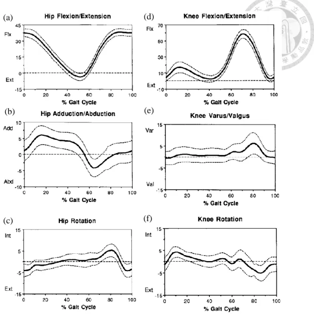
healthy testers with no previous history of musculoskeletal problems and measure the rotation of pelvic, hip joint, knee joint and ankle rotation. In this paper, we only discuss the result of hip joint and knee joint, because our design only contains hip joint to knee joint. Figure 2.4 shows the rotation of hip joint and knee joint. In Figure 2.4 (a) to (c), rotations of flexion/extension, adduction/abduction and internal / external rotation of the hip joint are shown respectively. Figure 2.4 (d) to (f) show the rotations of flexion/extension, varus/valgus and internal rotation, external rotation of the knee joint respectively. As the result, we can know the limit in rotation of hip and knee joint. In the rotation of hip joint, maximums of flexion, extension, adduction, abduction, horizontal adduction, and horizontal abduction are about 30°, 10°, 5°, 5°, below 5°, below 5°, respectively. In the rotation of knee joint, maximums of flexion, extension, varus, valgus, internal rotation, and external rotation are 60°,0°,5°,0°, below 5°, below 5°, respectively.
Figure 2.3 Method of gait analysis (a) Stereo metric set up and force plate in Cappazzo research [27]. (b) Marker configuration and embedded coordinate systems in Cappazzo research [27]. (c) Stereo metric set up and force plate in Kadaba’s research [28]. (d) Marker configuration and embedded coordinate systems in Kadaba’s research [29].
(a) (c)
(b) (d)
Figure 2.4 Mean (thick line) and one standard deviation (dotted lines) of hip and knee rotation (a) Hip flexion and extension (b) Hip adduction and abduction (c) Hip internal and external rotation (d) Knee flexion and extension (e) Knee adduction and abduction (f) Knee internal and external rotation
(a)
(b)
(c)
(d)
(e)
(f)
2.1.3 Design target
After discussing the results, we can get a gait cycle, as shown in Figure 2.5(a) in which there are two phases of the gait, double support phase and single support phase. There are also two phases in single support phase, stand phase and swing phase. And then the actual degrees with gait cycle as shown in Figure 2.5(b). Later, we combine the coordinate systems of joint with these gait analysis and design our assist device.
Hip joint is a ball and socket joint with three degrees of freedom, which include rotation of flexion/extension, adduction/abduction and internal / external rotation.
Although hip joint is a ball and socket joint, we couldn’t design ball and socket joint on the device as hip joint. The assist device is mounted on the human body, and can’t be the same as the hip joint in the human body. In order to design a hip joint in our assist device to fit in with the hip joint of human body, we design two axes like the axes of 𝑒1 and 𝑒2 in hip joint coordinate system which defined by ISB above. Axis 𝑒1 is perpendicular to the sagittal plane, and axis 𝑒2 is perpendicular to the frontal plane. We made two axes extend and cross the center of hip joint in the human body and they are perpendicular to each other. According to this condition, the motion of the hip joint on assist device can confirm the motion of human’s hip joint as shown in Figure 2.5(c). We ignore the axis 𝑒3 here, because the rotation on axis 𝑒3 is very small. The value which is below 5° is the minimum in all rotation of the hip joint. Also, if we want to design the axis 𝑒3 and confirm the motion of human’s hip joint, axis 𝑒3 needs to extend and cross with 𝑒1 and 𝑒2 at the center of hip joint in the human body. With the statement above, it is really hard to design an axis whose rotation is so small on axis 𝑒3 extending to hip joint on assist device, so we don’t design it.
As for the knee joint which is a hinge joint with slide degree of freedom, we don’t care about the slide motion and don’t use the motor on knee joint in order to simplify the design. In our design, we provide the assist device to the elderly who have the ability to walk. So we don’t need the motor to control the knee rotation. We use a hinge joint to fit in with the knee rotation, which follows the rotation of human knee. In particularly, we design a sliding groove and slider mechanism for preventing falling on knee.
Preventing falling mechanism is combined with the gait analysis and the detail will be described later.
Figure 2.5 Gait cycle (a) Human walking cycle which is divided into single support phase and double support phase [29]. (b) Human's right leg walking cycle with actually degrees [30]. (c) Design purpose on hip joint.
(a)
(b)
(c)
Rotation point (hip joint)
Axes e1
Axes e3
2.2 Device detail
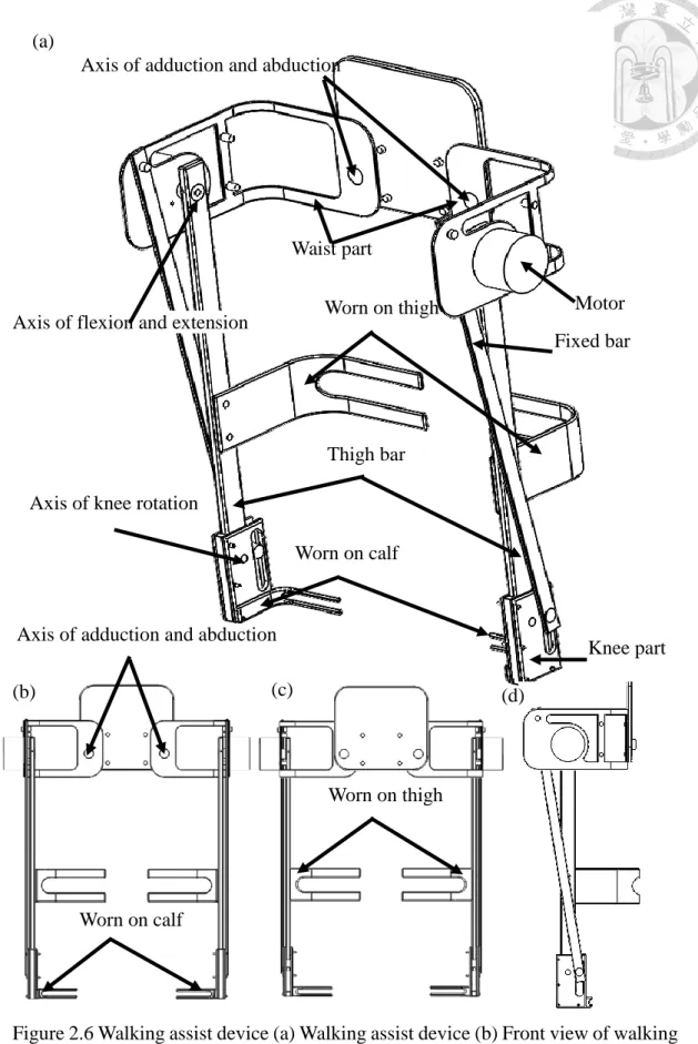
In this section, we will introduce our mechanism of lower limb assist device. Figure 2.6(a) shows the detail of the assist device which contains the component and the three axes on the assist device. There also exists a motor which is mounted on the axis for rotation of flexion and extension. Figure 2.6(b) to (d) show the front view, back view, side view respectively. The middle of the assist device is a square board which has four short shafts and two bigger shafts. The four shafts are for the purpose of worn around the waist with the belt. The bigger shafts are the axes of abduction and adduction, which connect the components of waist. Figure 2.7 shows the components of waist (Figure 2.7(b)) and the components of bar connecting the hip joint and the knee joint. We would call the components of waist and the components of bar connecting the hip joint and the knee joint for waist part and thigh bar respectively. Figure 2.7(b) to (e) show the waist part, top view of waist part, front view of waist part, side view of waist part respectively. There are many holes in Figure 2.7(d), the axis of flexion and extension is mounted on the hole.
There exist different sizes of holes in Figure 2.7(e), the bigger hole which represents the axis of motor is surrounded by three small holes. The three small holes are screw holes for the fixation of the motor. And the hole on the top left of the waist part is used to mounted the fixed bar. The waist part is hollowed to make it light. The middle of the hollow place contains a rectangle cylinder which has two holes to be worn on the waist.
Figure 2.7(f) to (i) show thigh bar, top view of thigh bar, side view of thigh bar, front view of thigh bar respectively. A hole on the side of the thigh bar as shown in Figure 2.7(h). The hole is a screw hole to mount the rigid shaft coupling on. In Figure 2.7(i), there are four holes. The one on the top is to place the rigid shaft coupling, and the other one on the bottom is the hole for connecting the axis of knee. Two other holes in the
middle are the holes mounting the thigh worn part.
Figure 2.8 shows the wear of the thigh and the calf, and we would call them thigh worn part and calf worn part as shown in Figure 2.8(b) and (f) respectively. Figure 2.8 (c), (d), (e), (g), (h), (i) are the top view of thigh worn part, front view of thigh worn part, side view of thigh worn part, top view of calf worn part, front view of calf worn part, side view of calf worn part respectively. The holes on the three-dimensional diagrams above are screw holes for mounting on the device, helping to wear on human body. Finally, Figure 2.9(b) and (f) are the fixed bar for preventing falling and the component on knee, we would call them fixed bar and knee part respectively. Figure 2.9(c) to (d) are the top view of fixed bar, front view of fixed bar, and side view of fixed bar respectively. Figure 2.9(d) shows two holes, the one on the top is mounted on the waist part, and the other one on the bottom is combined with the slider which slides in the sliding groove on the knee part. Figure 2.9 (g) to (i) are the top view of knee part, rear view of knee worn part, and side view of knee part. In the back view of knee part, it has a deep notch. It was difficult to be fabricated, so we separated the knee part into three parts, as shown in Figure 2.9(j).
Knee part is separated into two same L-shaped part vise. There are many holes in Figure 2.9(i), the four holes are screw holes for fabricating the knee part, and the other bigger hole is for mounting the axis of knee. There has the rectangle notch in Figure 2.9(i), it provides the sliding groove for preventing falling mechanism. With the slider move up and down in the sliding groove, we can realize the purpose of preventing falling.
Figure 2.6 Walking assist device (a) Walking assist device (b) Front view of walking assist device. (c) Back view of walking assist device. (d) Side view of walking assist
Axis of adduction and abduction
Axis of flexion and extension
Motor Worn on thigh
Worn on calf
Worn on thigh
Worn on calf
Axis of adduction and abduction (a)
(b) (c) (d)
Axis of knee rotation
Waist part
Thigh bar
Fixed bar
Knee part
Figure 2.7 Component of assist device (a) Walking assist device. (b) Waist part of walking assist device. (c) Top view of waist part. (d) Front view of waist part. (e) Side view of waist part. (f) Thigh part of walking assist device. (g) Top view of thigh bar. (h) Side view of thigh bar. (i) Front view of thigh bar.
(a)
(c)
(e) (g)
(b)
(i)
(f) (d)
(h)
(a) (b)
(c)
(d) (e)
(f)
(g)
(h) (i)
Figure 2.8 Component of assist device (a) Walking assist device. (b) Thigh worn part of walking assist device. (c) Top view of thigh worn part. (d) Front view of thigh worn part. (e) Side view of thigh worn part. (f) Calf worn part of walking assist device. (g) Top view of calf worn part. (h) Front view of calf worn part. (e) Side view of calf worn part.
Figure 2.9 Component of assist device (a) Walking assist device. (b) Fixed bar of walking assist device. (c) Top view of fixed bar (d) Front view of fixed bar. (e) Side view of fixed bar. (f) Knee part of walking assist device. (g) Top view of knee part.
(h) Back view of knee worn part. (i) Side view of knee part. (j) Exploded view of knee part.
(a)
(d) (c) (b)
(e)
(f) (g)
(h) (i)
(j)
2.3 Preventing falling mechanism
In this section, we would discuss about the operation of preventing falling mechanism.
Figure 2.10 shows the side view of walking assist device. The knee part is changeable based on the human gait. The slider inside the sliding groove can differ due to different gaits. From Figure 2.10(b), a simplified path of thigh bar and fixed bar, the knee part which is driven by the thigh bar rotates with the motor axis which is located at the waist part. Since the waist part is worn on a human body, it can be regarded as a fixed end. As for the fixed bar, it is also be seen as a fixed end because of its rotation around the hole of fixed bar on the waist part. We assume that the knee part doesn’t move relative to the thigh bar. That is, there isn’t rotation in the knee joint. The calf forms a straight line with thigh. Based on this assumption, the sliding groove consequently rotates around the motor axis just like the thigh bar. We can observe that the two fixed ends possess their own trajectories while they are rotating. However, the rotation of the fixed bar is driven by the thigh bar, and the lengths of the two bars are different. If the fixed bar rotates the same angle as the thigh bar, the two bars will stuck due to different trajectories. As a result, we add a slider and sliding groove to generate a new degree of freedom, avoiding being stuck.
The fixed bar will have a new rotating angle due to the slider. Furthermore, we apply this method to restrict the relative rotation between the thigh and calf for preventing falling mechanism. First, we must know the probable motion caused by the slider to decide a suitable time to fix the thigh bar. The relative rotation between the thigh bar and knee part is expected to be fixed in the instable gait of single support phase, restricting the relative rotation between the thigh and calf of human body. As for the influence caused by the position of slider, we consider the widths of thigh bar and knee part. Since the edge of thigh bar fits in with the sliding groove, the slider can move fluently when the thigh bar
is attached to the knee part as shown in Figure 2.10(c). On the other hand, the fixed bar slides up and down as the thigh bar rotates clockwise and counterclockwise respectively.
And then with the gait analysis, both right and left legs rotate clockwise after touching the ground when they are under single support phases as shown in Figure 2.4(a) and (b).
The slider may therefore slide up based on the above characteristic. Figure 2.10(d) shows the inner structure of the knee part. The height of the slider is equal to the axis of knee part initially. The thigh bar can consequently rotate when the slider slides down, providing a degree of freedom for the rotation of knee joint. And when the slider moves up, the fixed bar will seize the slider to restrict the downward rotation of the thigh bar. Therefore, the relative motion between the thigh and calf is restricted under single support phase.
And under swing phase, the thigh bar rotates counterclockwise to make the slider move downward. Thigh again receives a relative rotation with respect to calf. Under above situation, we can provide the walking assist device with both fixation and free capabilities to prevent falling. As for the assumption of the knee part doesn’t move relative to the thigh bar. It don’t influence preventing falling mechanism because when the hip rotation rotate in clockwise, it don’t have any rotation on knee joint. The rotation on knee joint will happen on hip joint to neutral and the hip joint rotate in counter clockwise.
Figure 2.10 Preventing falling mechanism (a) Side view of walking assist device.
(b) Path of thigh bar and fixed bar. (c) Side view of knee part (d) Knee anatomy.
(a) (b)
(c) (d)
2.4 Mechanism model 2.4.1 Mechanism model
We discuss model of our assist device and restriction in preventing falling system.
Based on our assumption above, we draw a side view of walking assist device in Figure 2.11. We set the length between hip joint to knee joint as
r
1, the length between the rotation center of knee to the slider center asr
2, the change length of the slider in the sliding groove asr
3 , and define moving upward as positive, moving downward as negative. The length of the fixed bar isr
4, the length from motor shaft to the center ofthe fixed end shaft is
r
5. And
1, , , ,
2 3 4 5 are the angle betweenr r r r r
1, , , ,
2 3 4 5 and level line. And we set the rotation of hip joint is
and the rotation of knee joint is
, and define counter clockwise is positive and clockwise is negative. According to the vector loop in the figure, we can obtain the equation below1 2 3 4 5
r r r r r
(2.1)We divide the vector to x and y direction and as shown in equation (2.2) and (2.3).
1
cos
1 2cos
2 3cos
3 4cos
4 5cos
5r r r r r
(2.2)1
sin
1 2sin
2 3sin
3 4sin
4 5sin
5r r r r r
(2.3)Among of above,
r r r r
1, , ,
2 4 5 and
5 are constant,
1, , ,
2 3 4 andr
3 arevariable. The variable value would change by the rotation of hip joint
and the rotationof knee joint
which have specific value at specific gait. Because of the specific degrees within the gait, we can knowr r
1, , , ,
2
1 2 3 above,r
1 is defined by the length of thigh (hip joint to knee joint).r
2 , which is due to the length of knee joint to the center of the sliding groove, andr
2 is perpendicular tor
3.
1 is depended on therotation
.
2 and
3 are depended on
and
whose value can be known with the gait cycle. The degree can show in equation (2.4) to (2.6)1
270
(2.4)2
180
(2.5)3
270
(2.6)And then, with equation (2.2) and (2.3), we have two equations but
r
3r r
4, , ,
5
4 5are unknowns. We don’t have enough equations to solve the unknowns. With the different gait, we can get two more equations. But
r
3 and
4 is variable, we get two more unknowns with the two more equations. The unknown still can’t be solve, so we need to discuss the value ofr
3 for reducing unknown and solving value for the mechanism.r
3is an important value on preventing falling which is the displacement of the slider in preventing falling mechanism and changed by the gait. We have talked about the preventing falling mechanism in section 2.3. Although
r
3 is variable value with the gait changing, we set specific value on the specific gait for preventing falling mechanism.First, we set the height of the slider center same as the knee joint when
0 as shownmoves upward when
rotates clockwise and moves downward when
rotates counterclockwise. So we can know that when 0, r
3 0
and equation (2.2) and (2.3) can be rewritten as2 4
cos
4( 0) 5cos
5r r
r
(2.7)1 4
sin
4( 0) 5sin
5r r
r
(2.8)In equation (2.4) and (2.5), there are two known:
r
1 andr
2 four unknowns:4
, ,
5 4( 0),
5r r
. Comparing with the equations and unknowns above, we only emerge onemore unknown
4(0), but we have two more equation. We reduce unknown with settingthe specific
r
3. And then, we set another specificr
3 on other specific gait. Figure 2.11 (c) and (d) show the thigh bar rotating to 10° clockwise, this situation is on stand phase with single support as Figure 2.5(a) showing which is the situation need to fix the relative rotation between thigh and calf we discuss in section 2.3. So we choice a specificr
3 at this gait and the equation (2.2) and (2.3) can be rewritten as1
cos
1 2cos
2 3( 10 . )c wcos
3 4cos
4( 10 . )c w 5cos
5r r r
r
r
(2.9)1
sin
1 2sin
2 3( 10 . )c wsin
3 4sin
4( 10 . )c w 5sin
5r r r
r
r
(2.10)Combing with equation (2.4) to (2.6) the equation can rewritten as
1
sin
2cos( )
3( 10 . )c wsin( )
4cos
4( 10 . )c w 5cos
5r r r
r
r
(2.11)1
cos
2sin( )
3( 10 . )c wcos( )
4sin
4( 10 . )c w 5sin
5r r r
r
r
(2.12)In equation (2.11) and (2.12), we get two more equations and one more unknown
4( 10 . )c w
. Combining with equation (2.7) and (2.8) we have four equations and fiveunknowns. If we set another specific
r
3, we can have six equations and six unknowns.But both specific
r
3 in equation (2.7) and (2.11) are fit with the preventing falling system on specific gait. We don’t have one more restriction to solve the problem. We can set any value ofr
3 for solving the unknown. It means we have any value ofr r
4, , ,
5
4 5. But with the preventing falling system, we have the restriction 0, r
3 0
, 0, r
3 0
and
0, r
3 0
. And others restriction are set with our discussion above. Combining therestriction, we can set the value of
r
3 in the range of the restriction. And we have six equations and six unknowns, then we can get actually value. So we choice the suitable valuer
3 when
is in counter clockwise. The value would fit with the restriction we would discuss in next section.38
Figure 2.11 Side view of walking assist device (a) In degree. (b) Geometry in degree. (c) In clockwise degrees. (d) Geometry of clockwise degree. (e) In counter clockwise degree and clockwise. (f) Geometry of
counter clockwise degree and clockwise
1 r5
r4
r2
r1
2
4
5
(a) (b)
(c)
(d)
(e) (f)
1 r5
r4
r2
r1
2
4
5
r3 3
r5
r4
r2
r1
r3
3
5
4
2
2.4.2 Dimension and restriction of the assist device
Next, we need to calculate the actual size of the assist device to manufacture the first prototype. Finding the problem and make experiments on first prototype, and modify it on better size. First, we consider the restrictions in every components depended on the connection or method of fabrication, and then we find the restrictions from human body.
Finally we will discuss the restriction in preventing falling mechanism. Combing these restrictions mentioned in this section and the model above, we can make a new assist device directly if we need to make some changes on the sizes of any components.
First we would discuss the restriction on waist. Based on the above discussion of the hip joint, we wanted to make axes (flexion/extension and adduction/abduction) cross at the center of hip joint in human body. Because of that, we need to make two axes at the same height on the waist part, fitting in with the human’s hip joint. And then the motor and the fix bar can be mounted on the waist part. The distance of both center needs to be bigger than the motor’s radius so that the fixed bar and motor would not collide. The height of the waist part depends on the distance of motor center and the fixed bar. The height of the waist part also depends on the size of the motor. We use sheet-metal to make our waist part, so the thickness is restricted by sheet-metal fabrication. The restriction of the human body on waist part is the length to which need to fit in with the size of human’s waist.
As for the thigh bar, the width depends on the knee part for preventing falling mechanism. The thigh bar is the thickest component in our device, because the thigh bar would support some weight of human’s thigh. And the length of thigh bar depends on the length between human’s hip joint to knee joint. To make sure that the thigh bar covers human’s thigh tightly, the thigh bar is worn on the middle segment of human’s thigh since
The length of the knee part is fitted in with the height of human’s knee and the sliding groove. Because of preventing falling mechanism, the width of the knee part depends on the width of thigh bar and the sliding groove. The thickness of the knee part is based on the thigh bar. And then the wear on the knee is set at the bottom of the knee part in order to make relative rotation between the thigh bar and knee part easier.
Then, we add the restrictions of the components and combine with the equations (2.7) to (2.12). First, we talk about the waist part. Because of the sheet-metal fabrication, we set the thickness of waist part as 3mm for fabricating conveniently. The waist part need to be surrounded the wearer’s waist. As the result, we set 165mm and 210mm as the lengths of the front and side of the waist part respectively. Based on sheet-metal fabrication, the waist part and thus the heights of front view and side view of the waist part are same. The size of height depends on the size of motor. Figure 2.12 shows the detail of Maxon motor EC-60 flat. Since we know the size of the motor, we can get the restriction information that
r
5 is smaller than 34mm.Next, we talk about the thigh bar, we choose 10mm to be the thickness of thigh bar, and then we know that the rigid shaft coupling have 20mm in diameter. We can know our width or hip bar need to be bigger than 10mm. Finally 450 mm is selected to be the length of the thigh bar based on the wearer’s thigh.
As for the size of knee part, the wear portion is set at the bottom of the knee part to let the wear more convenient, so that the length of the knee part can be decided by the wearer’s knee height. And the width of the knee part depends on the width of thigh bar and the sliding groove in the preventing falling mechanism. In the other hand, we separate the knee part into three parts for convenience. The thicknesses of the three piece parts are 5mm, 10mm, 5mm. The knee part can be assembled via the three pieces. Finally, we talk about the size of the sliding groove. We choose 16mm as the width of the sliding groove
since that the slider is a cylinder whose diameter is 16mm. And the length of the sliding groove depends on the path of the slider. The path is chosen based on the limit of the rotation of hip joint (clockwise 10° to counterclockwise 30°).
The length of the fixed bar is
r
5 which depends on the preventing falling mechanism.The width of the fixed bar is chosen via the diameter of the fixed cylinder. And then we combine all the restrictions mentioned above to get some restriction terms.
5
34( )
r mm
(2.13)1
450( )
r mm
(2.14)2
10( )
r mm
(2.15)0, r
30
(2.16)0, r
30
(2.17)0, r
30
(2.18)At last we need to find the value of
r
3, its length which influences the length of sliding groove. Actually, if the height of knee part is constant, the length of the sliding groove is as longer as better. That is, we can reduce the weight of knee part, making the assist device lighter. When the upward value ofr
3 is bigger, the preventing falling mechanism would be better. However, the bigger upward value of 𝑟3 would cause the bigger downward value ofr
3. It means there must need a bigger knee part to fit the sliding groove. As a result, we set the maximum upward value 20 mm for preventingfalling system. Then, we need choice a value of
r
3 when
is counter clockwise and
is clockwise. First, we want to talk about fall-preventing mechanism when0, r
30
. We discuss equation (2.17) and combine with equation (2.2) and (2.3). Here1
, , , ,
2 3 4 5r r r r r
are the length, must be positive in equation (2.2). Combining with Figure2.11 (d), x component in equation (2.2) of left side is depended on
r r r
1, ,
2 3 andr
1 is the biggest within input lengths (r r r
1, ,
2 3). It also show in Figure 2.11 (d). So the left side in equation (2.2) is negative and the equation hasr r
4,
5 at the right side.r
4 is bigger thanr
1 because of fall-preventing mechanism. Ifr
4 is smaller thanr
1, the value ofr
3would not have obvious value and the slider can’t work in preventing falling we discuss in section 2.3. The right side of equation (2.2) also need to be negative, but
r
4 is bigger thanr
1,r
5 need to be positive to fit the equation. Combing with all situation above,r
5and
5 need to fit with the equation. We can know that
5 I IV ,
and it has similar situation on equation (2.3) with equation (2.18) when 0, r
3 0
in Figure 2.11 (f). We can also get
5 I II ,
, so
5 is in the first quadrant. Combing all discussion above, weneed to choose a value of
r
3 in another gait. Here we choose the maximum downward value on the gait when hip joint rotates 20° counter clockwise and knee joint rotates 60°.Then we have six equations and
![Figure 1.4 HONDA walking assist device (a) Walking Assist Device with Stride Management Assist [17]](https://thumb-ap.123doks.com/thumbv2/9libinfo/9606853.632770/19.892.124.785.119.879/figure-walking-walking-assist-device-stride-management-assist.webp)
![Figure 1.5 Assist device : HAL (a) HAL: Hybrid Assistive Limb [21]. (b) Patent of Hybrid Assistive Limb [22]](https://thumb-ap.123doks.com/thumbv2/9libinfo/9606853.632770/21.892.132.776.120.1040/figure-assist-device-hybrid-assistive-patent-hybrid-assistive.webp)
![Figure 1.6 REWALK TM (a) REWALK TM and its pilot [23]. (b) Patent of REWALK TM [24]](https://thumb-ap.123doks.com/thumbv2/9libinfo/9606853.632770/23.892.161.451.126.504/figure-rewalk-tm-rewalk-tm-pilot-patent-rewalk.webp)
![Figure 2.2 Motion of lower limb (a) Cardinal planes of motion [26]. (b) Hip motion of flexion and extension [26]](https://thumb-ap.123doks.com/thumbv2/9libinfo/9606853.632770/28.892.121.771.120.929/figure-motion-cardinal-planes-motion-motion-flexion-extension.webp)
![Figure 2.3 Method of gait analysis (a) Stereo metric set up and force plate in Cappazzo research [27]](https://thumb-ap.123doks.com/thumbv2/9libinfo/9606853.632770/31.892.146.782.112.980/figure-method-analysis-stereo-metric-force-cappazzo-research.webp)
![Figure 2.5 Gait cycle (a) Human walking cycle which is divided into single support phase and double support phase [29]](https://thumb-ap.123doks.com/thumbv2/9libinfo/9606853.632770/35.892.132.788.112.790/figure-human-walking-divided-single-support-double-support.webp)