國立臺灣大學電機資訊學院電機工程學系 碩士論文
Department of Electrical Engineering
College of Electrical Engineering and Computer Science
National Taiwan University Master Thesis
MIFARE Classic 上的實務攻擊與防禦
Practical Attacks and Defenses of MIFARE Classic
池明洋
Ming-Yang Chih
指導教授:鄭振牟 博士 Advisor: Chen-Mou Cheng, Ph.D.
中華民國 99 年 6 月
June, 2010
誌謝
在台大兩年的碩士生活首要感謝我的兩位指導教授 鄭振牟 博士與 楊柏因 博士:感謝鄭老師兩年來耐心、細心的指導我這塊朽木,在研究的路上提供我持 續不斷的支援以及協助,教導我做人處事的道理;感謝楊老師總是能在我士氣低 落時,帶給我歡笑,使我能再次挑戰困難的問題。兩位老師提供我一個很棒的研 究環境,讓我在研究上、生活上皆無憂慮。感謝兩位年輕又優秀的學者兩年的研 究指導,僅在此至上最誠摯的謝意與敬意。
其次感謝 631 全體的同學:周彤、麋鹿、CS、蕭老、大明星、歐文,他們 給我許多研究上的建議以及指導。不論什麼時候有什麼問題,大家都相當樂意幫 我解決。特別是歐文總在我需要的時候,無私的幫我解決很多研究上的問題。感 謝以上的戰友們及學弟們一次次配合與參與,我所安排的實驗室活動,希望各位 能有研究以外共同的回憶。
再者感謝台大棒球隊兩年來的照顧,感謝多位已畢業的學長分享許多職場以 及過往的趣事。感謝現役的學弟在每次練習以及比賽的幫助。有你們每一分的努 力才讓我們這兩年的大專決賽能有這樣好的表現,感謝你們給我這麼好的回憶,
謝謝。
最後要感謝我的女友不間斷的關心,督促著我的學習。謹以此論文獻給每一 位愛我及我愛的人。
池明洋 2010/6/26
於台大電機所 631 快速密碼實驗室
摘要
MIFARE Classic 是近年來最廣泛被使用的非接觸式智慧卡,應用在門禁、大 眾運輸工具、電子錢包等系統上。MIFARE Classic 上密碼保護機制與結構已被發 表在許多的論文上。在本論文中我們提出各式各樣在 MIFARE Classic 攻擊實作的 經驗。我們實作兩類的攻擊:一是假造讀卡機、二是側錄合法的交易。第一類的攻 擊在兩天內利用 NVIDIA 高速運算顯示卡上實作密鑰的窮舉搜尋法與隨機數和連 認證的漏洞離線的破解卡片上所有的金鑰。第二類是針對 MIFARE Classic 加解密 器: CRYPTO-1 上攻擊方法的改進。經過我們的改進,攻擊者不僅可以破解自己的 卡同時也能破解別人的卡。我們所實作的攻擊徹底讓 MIFARE Classic 的密碼保護 失去效用,讓未經授權的攻擊者能任意更改卡片上資料,如同沒有任何保護的記 憶卡。更進一步,我們提出有關防止目前已知的攻擊的建議,而此防禦機制加強 對卡片資料的防護並加強後端清算機制的效率。
關鍵字: MIFARE Classic, CRYPTO-1, cryptanalysis, GPU, RFID security.
Abstract
MIFARE Classic is a proprietary contactless smart card technology widely used in public transportation ticketing systems of cities across the world. MIFARE Classic’s cryptographic protection to the stored data has been reverse-engineered and broken in a recent series of papers. In this thesis, we report our experiment experiences attacking a real MIFARE Classic system. Specifically, we implement a brute-force search using NVIDIA graphics cards to verify the claims in the literature. We also implement and improve more advanced attacks that take advantage of other design and implementation flaws of CRYPTO-1, MIFARE Classic’s proprietary cipher. These attacks disarm all cryp- tographic protection of MIFARE Classic and in effect render it a contactless memory card technology. Last but not least, we present our ideas how to defend against most attacks using practical mechanisms that do not require any hardware changes. Our proposed mechanisms can be easily implemented on a variety of MIFARE Classic readers on the market and only require commodity PCs be used in the backend system with intermittent network connectivity.
Keywords: MIFARE Classic, CRYPTO-1, cryptanalysis, GPU, RFID security.
Contents
Abstract 1
1 Introduction 6
1.1 Background . . . 7
1.2 Motivation . . . 8
1.3 Problem Statement . . . 9
1.4 Contribution . . . 10
1.5 Thesis Outline . . . 11
2 MIFARE Classic 12 2.1 Linear Feedback Shift Register (LFSR) . . . 13
2.2 Structure of CRYPTO-1 . . . 13
2.2.1 Non-Linear Filter Function . . . 14
2.2.2 Keystream Generation . . . 15
2.3 Memory Structure . . . 16
2.4 Command Set . . . 17
2.5 Communication Protocol . . . 19
2.6 Other Components in MIFARE Classic . . . 20
2.6.1 Pseudo Random Number Generator (PRNG) . . . 20
2.6.2 The Encrypted Parity . . . 21
2.6.3 Encrypted Error Code 0x5 . . . 21
3 Experiment Setup 23
3.1 Sniffer . . . 23
3.1.1 Universal Software Radio Peripheral (USRP) . . . 23
3.1.2 GNU Radio . . . 24
3.1.3 Sniffer Implementation . . . 24
3.1.4 Converting to Raw Data to Packets . . . 25
3.2 Proxmark3 . . . 29
4 Our Attacks on MIFARE Classic 31 4.1 Time-memory Trade-off in Attacking CRYPTO-1 . . . 31
4.2 Weakness in CRYPTO-1 and its Implementation . . . 32
4.2.1 CRYPTO-1 Structure . . . 32
4.2.2 Plaintexts that Provide Consecutive Keystream Bits . . . 33
4.2.3 Implementation Vulnerabilities . . . 34
4.3 PCD-based Attack . . . 37
4.3.1 First-key Attack . . . 37
4.3.2 Remaining-key Attack . . . 40
4.4 Sniffer-based Attack . . . 43
4.4.1 Keystream to Internal States . . . 43
4.4.2 Attack Based on Two-way Traffic . . . 44
4.4.3 Long-distance Attack . . . 44
4.5 Comparison . . . 46
4.5.1 Implementation Improvement . . . 46
5 Proposed Defenses for MIFARE Classic 48 5.1 Multivariate PKCs: TTS . . . 49
5.2 System Design . . . 50
6 Conclusion 54
List of Figures
1.1 Sniffer-based Attack . . . 9
1.2 PCD-based Attack . . . 9
2.1 An Example of an LFSR . . . 13
2.2 The Structure of the CRYPTO-1 Cipher . . . 14
2.3 The Sequence of Seeding the CRYPTO-1 Cipher . . . 16
2.4 Memory Structure of MIFARE Classic 1K. . . 17
2.5 Communication Protocol Overview . . . 19
2.6 Anticollision for ISO-14443 Type-A . . . 19
2.7 Three-way Mutual Authentication . . . 19
2.8 Pseudo Random Number Generator . . . 21
2.9 The Encrypted Parity . . . 21
2.10 Flow of Reader Response Checking . . . 22
3.1 Block Diagram of the GNU Radio Sniffer . . . 25
3.2 Signal coding by frequently changing line codes in RFID systems . . . . 26
3.3 Normalized Raw Samples in an Oscilloscope . . . 27
3.4 Normalized Raw Samples for REQA (0x26) . . . 27
3.5 Raw Samples of ATQA (0x40) . . . 28
4.1 Nested Authentication Scheme . . . 35
4.2 Error-code Examination Scheme . . . 39
4.3 The Error-code Check Flow . . . 40
4.4 Guessing Nt2from Nt1 and Recovery from ks to Internal States . . . 41
4.5 Examination of the Recovered States . . . 43
4.6 Example Sequence of Commands . . . 44
5.1 Proposed Defense Mechanism on PICC . . . 51
5.2 Proposed Defense Mechanism on PCD . . . 52
List of Tables
2.1 MIFARE Classic Command Code Table . . . 18
2.2 An Example Error-code Trace . . . 22
4.1 An Example One-way Trace . . . 44
4.2 Platform Comparison in First-key Attack . . . 46
4.3 Experiment Results . . . 47
5.1 Speed of TTS on Various Platforms . . . 50
Chapter 1 Introduction
Developed and sold by NXP Semiconductors, Inc., MIFARE Classic is a proprietary con- tactless smart card technology widely used in public transportation ticketing systems of cities across the world, the most famous examples being Beijing’s OnePass, Boston’s CharlieCard, London’s Oyster Card, and Taipei’s EasyCard. As MIFARE Classic gets more and more popular, it is also being adopted in several cities as a means for imple- menting micro payment systems.
MIFARE Classic provides cryptographic protection to the stored data. Although the design and implementation of the cipher in MIFARE Classic are kept secret by NXP Semiconductors, the detail has been recovered and disclosed in a recent series of pa- pers [1, 2, 3, 4, 5, 6].
The core cryptographic primitive used by MIFARE Classic is a proprietary stream cipher called CRYPTO-1. It uses a 48-bit linear feedback shift register (LFSR) as state.
In each clock cycle, a fixed subset of the LFSR bits are fed into a non-linear filter function to generate one bit in the output keystream. For more details of the cipher, the interested reader is referred to Nohl et al. [3]
The most fatal design flaw of CRYPTO-1 is that the state space of 248 is too small.
For example, Garcia et al. estimated [5] that, given enough keystream bits or information about them, a brute-force search using an FPGA cluster like COPACOBANA [7] takes about 36 minutes. Furthermore, CRYPTO-1 has several other design and implementation
In this thesis, we report our experience attacking a real MIFARE Classic system, as well as present our ideas how to defend most attacks in practice. Specifically, we im- plement a brute-force search using NVIDIA Graphics Processing Units (GPUs) to verify the aforementioned claim made by Garcia et al. Moreover, we also propose and imple- ment a new long-range attack based on existing sniffing attacks that take advantage of CRYPTO-1’s other flaws. These attacks disarm all cryptographic protection of MIFARE Classic and in effect render it a contactless memory card technology. Lastly, we propose a set of practical mechanisms that can defend against most attacks without requiring any hardware changes.
1.1 Background
In jargon of the trade in the field of radio-frequency identification (RFID), an RFID tag is called a Proximity Integrated Circuit Card (PICC), whereas an RFID reader is called a Proximity Coupling Device (PCD) [8]. We will follow this terminology for the rest of this thesis.
There are several kinds of MIFARE Classic PICCs with different capacities. Take MIFARE Classic 1K as an example. The one-kilobyte memory is divided into 16 sectors, each with four 16-byte blocks. Each sector has a tail block, which has two 48-bit secret keys, called Key A and Key B, and a 32-bit condition for the sector’s access control.
The radio-frequency communication of MIFARE Classic consists of three phases:
anti-collision, three-way authentication, and memory operation. The anti-collision fol- lows the ISO-14443 standard [9], in which PCD selects a PICC by its unique identifier (UID). Anti-collision marks the beginning of a transaction, after which PCD can initiate a three-way authentication session if it wishes to access blocks in protected sectors. After the PICC receives an authentication command, it will first send out a tag challenge nonce Nt. This nonce, along with the PICC’s UID, is used to initialize the CRYPTO-1 cipher so that all subsequent messages exchanged can be encrypted. The PCD then sends out the reader response Ar based on Nt and a reader challenge nonce Nr. The PICC checks whether Aris as expected, and if so, it will send a tag response At, which is a function of
Nt(not Nr!), to the PCD. The authentication is concluded with PCD verifying whether Atis as expected.
After the three-way authentication is successful, all subsequent communication is en- crypted, including memory operations within the same sector as well as authentication requests for blocks in other sectors. Using the detailed command set recovered by Gans et al. [4], the attacker can easily launch a known-plaintext attack.
1.2 Motivation
Today in Taipei city, we can buy groceries and various merchandizes in convenient stores, ride buses and subways, and shop in department stores with EasyCard, which adopts the MIFARE Classic PICCs as the payment tool. Similar MIFARE-Classic-based systems are also deployed in Guangzhou, London, Boston, the Netherlands, . . . , etc. Moreover, in some systems MIFARE Classic PICCs are also used as e-cash.
MIFARE Classic is a kind of RFID technology with cryptographic protection Its ci- pher structure was regraded as confidential information by the companies who developed it, and hence the details had not been known to the general public. However, security can not be achieved through obscurity, and many security vulnerabilities of MIFRAE Classic have been discovered and disclosed in the past few years. Nevertheless, there has not been much study on the security of the affected systems, and the security needs to be examined as soon as possible by trusted third parities.
The purpose of this thesis is to investigate the security of MIFARE-Classic-based sys- tems after a thorough study of the related security vulnerabilities and issues of MIFARE Classic. We aim to act as an independent security examiner, the so-called “white hats”
who attack systems in good faith, give cost estimate of these attacks, and suggest ways to improve the systems’ security.
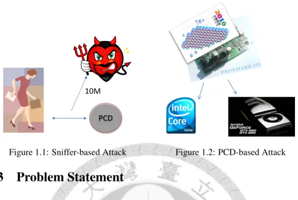
PCD 10M
Figure 1.1: Sniffer-based Attack Figure 1.2: PCD-based Attack
1.3 Problem Statement
There have been many different attacks, including PCD-based and sniffer-based attacks, published during recent years. Garcia et al. provided two kinds of PCD-based attacks using FPGA or CPU. They proposed to launch a brute-force search with information ob- tained via the “encrypted error-code” vulnerability to obtain the first key from a MIFARE Classic PICC. But they only had an estimation based on the cryptanalysis of DES using COPACOBANA, a specialized FPGA cluster for cryptanalysis [7]. Unfortunately we do not have access to such an expensive FPGA cluster, so we turn our attention to cheaper, off-the-shelf GPUs. We implement a brute-force attack on GPU platform and conclude that the attacker can easily obtain secret keys with PICC-only attack for their own PICC.
For previous sniffer-based attacks, they have to get the full traffic between PICC to PCD. However, since PICC uses load modulation, eavesdropping packets sent from PICC is difficult at distance. The antenna of the sniffer needs to be placed in very close prox- imity, so the two-way sniffer-based attack is not useful in practice. Hence, we would like to improve and devise a more practical attack with long eavesdropping distance. The long-distance attack can assist the attacker to learn the keys of innocent users’ MIFARE Classic PICCs.
1.4 Contribution
Our first contribution is to have implemented the PCD-based attack by using the cheaper GPU platform. Today’s graphics cards contain powerful GPUs to handle the increasing number of screen pixels in video games. Now GPUs have developed into a powerful, massively parallel computing platform that finds more and more interest outside graphics applications. In cryptography, there have been many attempts of exploiting the computa- tional power of GPUs [10, 11, 12]. Furthermore, there has been evidence that GPUs can be a quite competitive computing platform in terms of price-performance ratio [13, 14].
From a practical perspective, our implementation is more available than the others’. For example, in the Kuanghua market of Taipei, one can easily find that GPUs are fairly cheap and much more affordable than dedicated FPGA cryptanalysis machines like CO- PACOBANA. So our PCD-based attack is much more available. By using the PCD-based attack, it is easy to alter the content of the PICCs one already has access to. All one needs to do is to put it on a cracking device and wait for two days before one can recover all keys on the MIFARE Classic PICC.
Our second contribution is that we have improved the impractical two-way sniffer- based attack to a more practical long-range attack. We use GNU Radio, an open-source software radio platform [15] to implement the long-range sniffer. Specifically, we de- sign and implement a demodulator on GNU Radio that allows us to eavesdrop the data transmission. Our sniffer can certainly pick up the data exchanged in both direction when the antenna is close to the PICC. If the antenna is far from PICC but not too far from PCD, then our sniffer can pick up the transmission from PCD. To recover key from such one-way traces, we design and implement a new kind of known-plaintext attack.
Finally, we not only attack the MIFARE Classic but also give suggestions how to de- fend against these attacks for system administrator. The defense methods employ public- key signatures on PCD. We use a fast signature scheme so that we need only firmware modification on the PCD, without any hardware change. We hope our ideas can help the affected systems as an interim solution before MIFARE Classic is completely phased out
1.5 Thesis Outline
The rest of this thesis is organized as follows. In the beginning, we will introduce the recent research results about MIFARE Classic in Chapter 2. In Chapter 2, we will de- scribe the structure of the CRYPTO-1 stream cipher, the communication protocol, mem- ory structure, command set, and other security issues of MIFARE Classic.
Next, in Chapter 3, we will delineate our experiment environment. Our sniffer is based on the GNU Radio software radio platform and the USRP hardware, while we use Proxmark III to emulate PCD. We also use OpenPCD, an off-the-shelf reader with NXP’s MIFARE Classic chip, to interact with PICCs once we recovered their secret keys.
In Chapter 4 and 5, we will describe the attacks and the defense for the MIFARE Clas- sic system. Finally, we will conclude this thesis by summarizing what we have learned and providing suggestions for operators to alleviate the damage brought by the MIFARE Classic incident.
Chapter 2
MIFARE Classic
MIFARE is a product developed by the NXP Semiconductors, Inc., a subsidiary company of the Royal Philips Semiconductors, Inc., of the Netherlands. It is the most widely de- ployed contactless smartcard technology, with over one billion chips sold, as claimed by the producer. MIFARE Classic provides cryptographic protections such as data confiden- tiality. It is mainly achieved via mutual authentication between PCD and PICC using a proprietary stream cipher called CRYPTO-1. It also has a few proprietary commands for various memory operations. The command set, memory structure, and communication have been delineated by Gans et al. [4] They could also read a protected block without knowing the secret key. Subsequently, the structure of CRYPTO-1 has been reverse- engineered by Nohl et al. [3, 1] People have attacked the pseudo random number gen- erator, the non-linear filter function, and other structures of the cipher. All the above works concentrate on recovering keys from eavesdropping traces. Then, Garcia et al. in- vestigated more serious vulnerabilities [5] and found the vulnerabilities of the encrypted parity, the encrypted error code, and nested authentication. The following is mostly a recapitulation of their works to make this thesis self-content.
The cipher used by MIFARE Classic is called “CRYPTO-1,” which is a stream cipher with a 48-bit LFSR (linear feedback shift register) and a two-level non-filter function.
The structure of the cipher was developed and protected as a trade secret by NXP, but the circuit of the cipher was reverse-engineered.
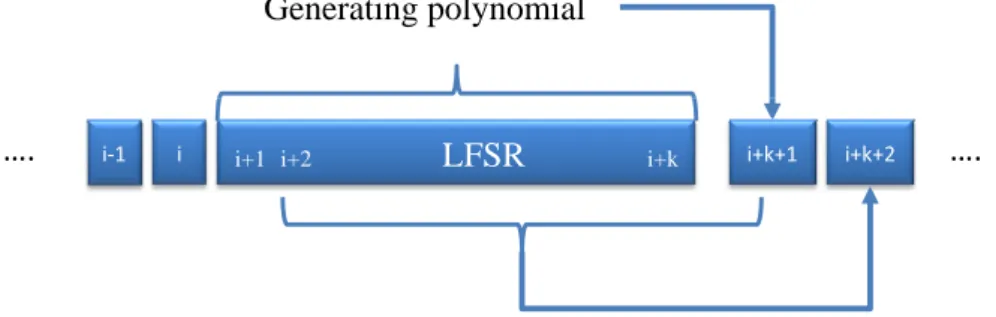
Generating polynomial
i+1 i+2 LFSR i+k i+k+1
i‐1 i i+k+2 ….
….
Figure 2.1: An Example of an LFSR
2.1 Linear Feedback Shift Register (LFSR)
LFSR is usually used as a pseudo random number generator (PRNG). Both the cipher and the PRNG in MIFARE Classic are LFSR-based. In general, LFSR consists of a fixed-sized registers initialized by some seed, which often consists of secret key, random number, UID, or a combination of some or all of them. As shown in Figure 2.1, the LFSR state shifts left (or right) a bit and is updated with a bit that is the bitwise XOR of some selected bits upon each clock cycle. The selected bits are taken from some fixed positions that are indicated by a generating polynomial, usually irreducible. Consequently, the same seeds are mapped to the same sequence of numbers, and the total number of states is restricted by the order of the generating polynomial.
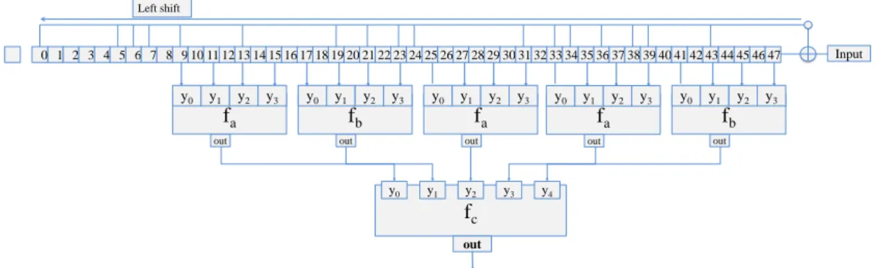
2.2 Structure of CRYPTO-1
As shown in Figure 2.2, CRYPTO-1 is composed of a 48-bit LFSR with following gener- ating polynomial
x48+x43+x39+x38+x36+x34+x33+x31+x29+x24+x23+x21+x19+x13+x9+x7+x6+x5+1,
as well as a non-linear two-level filter function, which will be described in Section 2.2.1.
The generating polynomial is interpreted as representing bit positions. Normally, x48 refers to the most significant bit, and the constant term, the least significant bit. In this thesis, we call the register state at a specific time as an “internal state.” A clock cycle
fc
y0 y1 y2 y3 y4
out 12
9 10 11 131415 1617 18 1920212223 24252627 28 4
1 2 3 5 6 7 8
0 2930313233 34353637 383940414243 44454647 Input
Left shift
out
fb
y0 y1 y2 y3
out
fa
y0 y1 y2 y3
out
fb
y0 y1 y2 y3
out
fa
y0 y1 y2 y3
out
fa
y0 y1 y2 y3
Figure 2.2: The Structure of the CRYPTO-1 Cipher
in CRYPTO-1 is 9.44 µs. The most significant bit is number 47, which is the bit being updated, as in Figure 2.2. In other words, the bits in any internal state satisfy the equation
x48+x43+x39+x38+x36+x34+x33+x31+x29+x24+x23+x21+x19+x13+x9+x7+x6+x5+1 = 0,
and we can move x48to the right side of the equation:
x43+x39+x38+x36+x34+x33+x31+x29+x24+x23+x21+x19+x13+x9+x7+x6+x5+1 = x48.
To summarize, the cipher calculates x48 by the above equation and shifts the bits appro- priately to generate the next state, which can be illustrated with the following example:
if the 48-bit internal state is 0x0123456789AB in big-endian notation, then the next state will become 0x0091A2B3C4D5 after one clock cycle.
2.2.1 Non-Linear Filter Function
The non-linear filter function is a two-level filter function consisting of fa, fb, fc: fa(y0, y1, y2, y3) = ((y0 ∨ y1) ⊕ (y0∧ y3)) ⊕ (y2∧ ((y0⊕ y1) ∨ y3))
fb(y0, y1, y2, y3) = ((y0∧ y1) ∨ y2) ⊕ ((y0⊕ y1) ∧ (y2∨ y3))
fc(y0, y1, y2, y3, y4) = ((y0∨(y1∨y4)∧(y3⊕y4))⊕((y0⊕(y1∧y3))∧(y2⊕y3)∨(y1∧y4)))
Filter Function
The filter function f : F248→ F2 is defined by f (x0x1...x47) = fc(fa(x9, x11, x13, x15), fb(x17, x19, x21, x23), fb(x25, x27, x29, x31), fa(x33, x35, x37, x39), fb(x41, x43, x45, x47)).
We note that total number of all possible inputs is 220. It appears that the output distribution of f is uniform in the sense that the function f outputs roughly the same number of zeros and ones.
2.2.2 Keystream Generation
The CRYPTO-1 stream cipher generates one bit of keystream, or one pseudo random number bit, as follows. The beginning of the operation is to select 20 bits from the odd positions between bit 9 to bit 47, or equivalently according to the polynomial
x47+x45+x43+x41+x39+x37+x35+x33+x31+x29+x27+x25+x23+x21+x19+x17+x15+x13+x11+x9,
as the 20-bit input to the non-linear filter function to calculate one bit of keystream. Sec- ondly, the cipher computes a updating bit by taking the fixed bits in internal register.
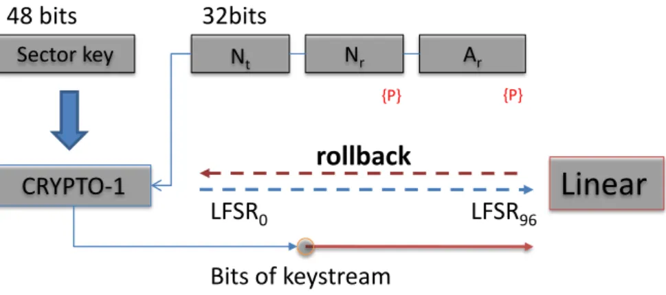
Thirdly, the internal state is shifted such that the least significant bit is thrown away while the most significant bit updated. In order to disturb the internal state, the cipher takes more seeds including U ID ⊕ Ntand Nrinto the internal state during initialization. These extra seeds are XOR’ed with the updating bit before the internal state is updated.
We note that the 48-bit internal state of the cipher can produce ten consecutive keystream bits without updating LFSR. This is because of the following. Assuming the internal state at a specific time t allows us to compute ten keystream bits at the time from t − 9 to t.
More clearly, we have
kst−i = x47−i+ ... + x9−i, ∀i = 9 to 0.
Nt Nr Ar
{P}
CRYPTO-1
Bits of keystream 32bits
{P}
Sector key 48 bits
LFSR0
rollback
LFSR96Linear
Figure 2.3: The Sequence of Seeding the CRYPTO-1 Cipher
This method will form a basis for some attacks later in this thesis.
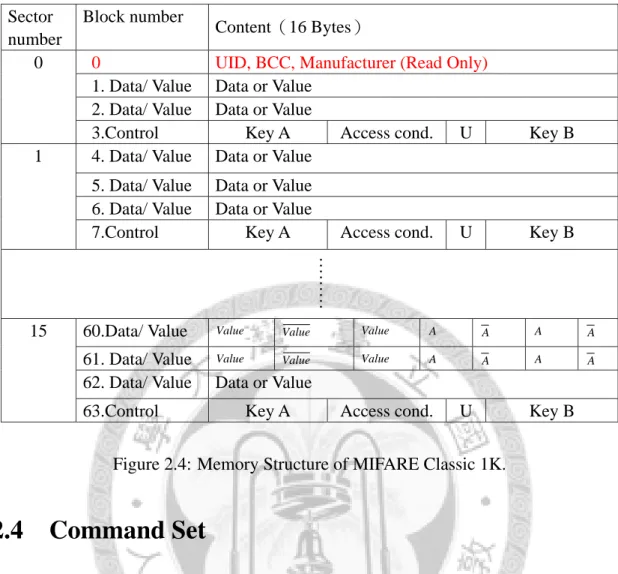
2.3 Memory Structure
MIFARE Classic PICC is a memory card with two different memory sizes, 1-kilobyte and 4-kilobyte. The memory is organized into sectors, each sector with four blocks, while each block consists of sixteen bytes. In each sector, every last data block is called a sector trailer, which is used to hold two sector keys, Key A and Key B, and a 3-byte access condition. A block is the minimum unit of memory, which can be a data block, a value block, or a manufacturer block. A data block can store 16 bytes of arbitrary data. The same block can also be configured as a value block, in which case it can record a four- byte value. The value in a value block is stored twice non-inverted and once inverted for data integrity consideration; see block 60 (or 61) of the memory structure example in Figure 2.4. sector [16, 17]. For a MIFARE Classic 1K PICC, the memory is divided into 16 sectors, as shown in Figure 2.4. For a MAFIRE Classic 4K PICC, it comprises 14 sectors with two different numbers of blocks, 4 and 16. Each of the first 32 sectors has four blocks, while the rest sectors have 16 blocks.
For both kinds of PICCs, the access condition controls access rights for each secret key (Key A or Key B) in this
Sector number
Block number
Content(16 Bytes)
0 0 UID, BCC, Manufacturer (Read Only) 1. Data/ Value Data or Value
2. Data/ Value Data or Value
3.Control Key A Access cond. U Key B
1 4. Data/ Value Data or Value 5. Data/ Value Data or Value 6. Data/ Value Data or Value
7.Control Key A Access cond. U Key B
………
15 60.Data/ Value Value Value Value A A A A
61. Data/ Value Value Value Value A A A A
62. Data/ Value Data or Value
63.Control Key A Access cond. U Key B
Figure 2.4: Memory Structure of MIFARE Classic 1K.
2.4 Command Set
A MIFARE Classic command is composed of a one-byte command, a one-byte block number, and a two-byte cyclic redundant check (CRC) code. In MIFARE classic pro- tocol, there are seven different commands, namely, READ, WRITE, AUTHENTICATE, INCREMENT, DECREMENT, RESTORE, and HALT, as shown in Table 2.1.
1. READ:
The command code is 0x30. To read a block. PICC will send back 16 bytes of block data and two bytes of CRC.
2. WRITE:
The command code is 0xA0. PCD writes 16 bytes of data to overwrite the entire data block in PICC. After the WRITE command, PICC returns a four-bit acknowl- edgment (ACK) to PCD. Then, PCD transmits 16 bytes of data to PICC. PICC optionally decrypts the data and writes to memory. If everything is correct, PICC sends to PCD an ACK again.
Operation Command Description
AUTHA 0x60 WW YY ZZ Use keyA to authenticate block 0xWW AUTHB 0x61 WW YY ZZ Use keyB to authenticate block 0xWW
READ 0x30 WW YY ZZ Read data from block 0xWW
WRITE 0xA0 WW YY ZZ Write data to block 0xWW DECREMENT 0xC0 WW YY ZZ Decrement value in block 0xWW INCREMENT 0xC1 WW YY ZZ Increment value in block 0xWW RESTORE 0xC2 WW YY ZZ Restore previous value in block 0xWW
HALT 0x50 00 57 CD Fixed command
Note WW is block number Two bytes CRC = 0xYYZZ Table 2.1: MIFARE Classic Command Code Table
3. Value commands:
The command codes for DECREMENT, INCREMENT, and RESTORE are 0xC0, 0xC1, and 0xC2, respectively. First, PCD sends a command, and PICC gives ACK.
Second, PCD sends a four-byte value followed by a two-byte CRC, along with
“TRANSFER” to PICC. PICC verifies the value with CRC and sends ACK again.
There are three value commands, INCREMENT, DECREMENT, and RESTORE.
“INCREMENT” is used to increment the value block by the value, “DECRE- MENT” is used to decrement the value block by the value, and “RESTORE” is used to restore the value block to previous value.
4. AUTHENTICATE:
Command codes are 0x60 for Key A and 0x61 for Key B. This command is for PCD to authenticate with PICC using the shared secrete keys. The communication protocol is shown in Figure 2.7 and described in Section 2.5.
5. HALT:
The command code is 0x50 and always takes zero block, so the complete command is 0X500057CD.
Anticollision
Three-way Mutual Authenitcation Memory Operations
Value Block
Read, Write, Inc, Dec, Trans, Res Data Block Read, Write
Figure 2.5: Communication Protocol Overview
PCD (Reader)
REQA ATQA SELECT
UID SELECT UID
Card Type
PICC (Tag)
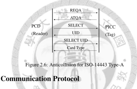
Figure 2.6: Anticollision for ISO-14443 Type-A
2.5 Communication Protocol
The communication protocol of MIFARE Classic is described in the ISO 14443 standard, type-A. Figure 2.5 gives an overview of the communication protocol that consists of three stages, namely, anti-collision, three-way authentication, and memory operation.
First of all, anti-collision, shown in Figure 2.6, selects the PICC with a unique iden- tifier (UID) around the electromagnetic field of the PCD. In a transaction, anti-collision
Auth
PCD N
t{ N } {
64(N ) }
PICC
{ N
r} { suc
64(N
t) } {suc
96(N
t) } { (
t) }
Figure 2.7: Three-way Mutual Authentication
is seen as the initialization between PCD and PICC and usually executes once. When the wireless connection becomes unstable, PCD will execute another anti-collision again to make sure that PICC is still available within its electromagnetic field. On real systems, if a PCD is going to access many blocks, the total transaction time may become longer. In this case, the PCD will divide memory operations into two or three groups and execute an anti-collision at the beginning of each group.
Secondly, PCD will choose a block number and a sector key (A or B) to authenticate with PICC. After PICC receives an AUTHENTICATE command, it will respond with a tag challenge nonce Ntand wait for the PCD to respond. As PCD sends Ar (suc64(N t)), computed based on Nt, and picks up a reader challenge nonce Nr, PICC inspects whether Aris correct or not. If it is correct, PICC will send a tag response At(suc96(N t)) to PCD.
PCD also checks Atagainst Ar to complete the mutual authentication. For internal state of the cipher, Ntand Nr would be used to seed into the internal state in order to disturb the internal state. This mechanism makes the keystream bits different from transaction to transaction.
Finally, the reader can operate accessible blocks in this sector dictated by the access condition at the sector tail.
2.6 Other Components in MIFARE Classic
2.6.1 Pseudo Random Number Generator (PRNG)
A PRNG generates a sequence of numbers that looks random. MIFARE Classic uses a PRNG based on a 32-bit LFSR with the generating polynomial x16+ x14+ x13+ x11+ 1.
In the actual MIFARE Classic PRNG implementation, it uses with only one seed. For example, assume we have a 32-bit random number b31, b30, ..., b0. We use little-endian notation for integers here so that 0x12345678 is b24. . . b31, b16. . . b23, b8. . . b15, b0. . . b7. The PRNG takes b32= b21⊕ b19⊕ b18⊕ b16, and then shifts right to throw away b0 while puts b32into the highest bit.
h b b
High bits Lower bits
32 31 21 19 18 16 15 0
Right shift
Figure 2.8: Pseudo Random Number Generator
Time
8 bits data P P
k
0k
1k
2k
3k
4k
5k
6k
78 bits data
k
8k
9… k
12k
13k
14k
15k
16……
31 15
Left shift
Lower bits High bits
0 13 12 10
Figure 2.9: The Encrypted Parity
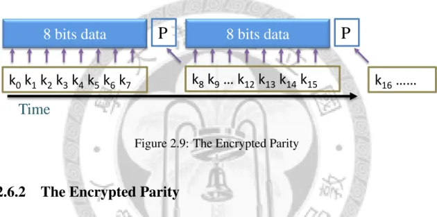
2.6.2 The Encrypted Parity
Use of parity is a simple method to check the data integrity. The MIFARE Classic, fol- lowing ISO 14443, uses a parity bit for every byte transmitted. In the implementation, the parity bits are computed before encryption and then encrypted using the next keystream bit, as shown in Figure 2.9. Assuming that the plaintext comprises 32 bits t1...t32and the keystream bits (r1...r33), the parity bits can be computed by the following equation:
pi = ti+1⊕ ti+2⊕ ... ⊕ ti+8⊕ ri+9⊕ 1, ∀i ∈ {0, 1, 2, 3}.
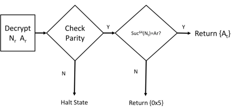
2.6.3 Encrypted Error Code 0x5
In a successful three-way mutual authentication, PCD authenticates PICC with shared se- cret key. As shown in Figure 2.10, when PICC receives a response {Nr}{Ar}, it decrypts the data to plaintext with its secret key, and the plaintext is checked against two condi-
Return {At} Decrypt
Nr Ar Check
Parity Suc64(Nt)=Ar?
Halt State
N N
Y Y
Return {0x5}
Figure 2.10: Flow of Reader Response Checking
Table 2.2: An Example Error-code Trace
Seq. Sender Code Explanation
1 - 6 ... Anticollision Exchange UID
7 PCD 0x6000f57b Authenticate block 0
8 PICC 0xf9105fce Nt
9 PCD {000000000} {000000000} Some random numbers
10 PICC {5} Error code 0x5
tions: (1) data parity, and (2) decrypted reader response Ar. If the data parity is correct but the reader response is not, the PICC will return an encrypted error code 0x5. If both conditions are satisfied, the PICC will send Atback. Otherwise, PICC will terminate the session without sending any packets.
Assuming that the keystream bits are more or less random from transaction to trans- action, the parities of {Nr}{Ar} will be correct with a probability of 1/256, in which case we will be able to collect an error-code trace as shown in Table 2.2. An error-code trace like this thus gives 12-bit information, four from the known plaintext error-code 0x5 and eight from the fact that the parities are correct, on a keystream that depends on the secret key used for authentication by the PICC.
Chapter 3
Experiment Setup
3.1 Sniffer
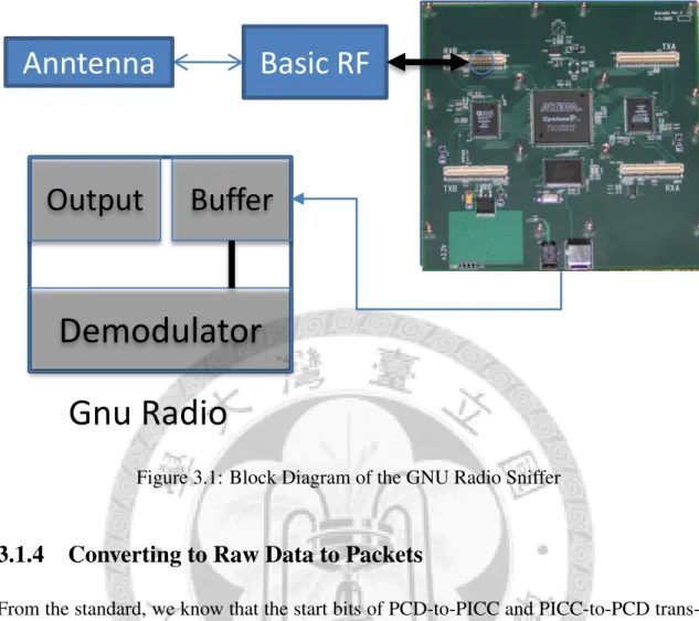
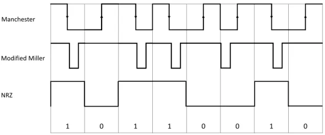
The communication of MIFARE Classic follows ISO-14443 Type-A standard, in which modified Miller code and Manchester code are used. We use the “Universal Software Ra- dio Peripheral (USRP)” to capture and digitize the signal. USRP converts the intercepted analog signal to digital form and transfers the raw samples across USB for further pro- cessing on PC. If a transaction happens between PCD and PICC, an appropriate antenna is around the magnetic field within a certain distance can capture the signal. The signal is then sent to the RF module on USRP, which converts to digital form and delivers the re- sulting samples to PC. We develop our own signal processing software on the GNU Radio open-source software radio platform, which allows programmers to create their own sig- nal processing blocks. In the following, we will describe our development environment, hardware device, and the sniffer implementation.
3.1.1 Universal Software Radio Peripheral (USRP)
USRP is designed to allow general-purpose computers to function as high-bandwidth software radios. Typically it is responsible for digital baseband and IF (intermediate fre- quency) sections of a radio communication system. The basic design philosophy behind USRP is to do all of the waveform-specific processing, like modulation and demodula-
tion, on the host CPU [18]. All of the high-speed general-purpose operations, like digital up- and down-conversion, decimation, and interpolation, are done on USRP’s FPGA.
Basic RF Module on USRP
USRP’s BasicRX is designed for use with external RF frontends as an IF interface. The ADC input is directly transformer-coupled to an SMA connector of 50-ohm impedance with no mixers, filters, or amplifiers. Our sniffer implementation takes the USRP and its basic RF module as the front-end digital and analog processor. In the following, we regard both devices as a DSP board.
3.1.2 GNU Radio
GNU Radio is a free software development toolkit that handles signal process routine by the software [15]. The simple the procedure on our sniffer can be considered as two parts: (1) raw data collection, and (2) data processing routine. These two parts form a loop that executes continuously. In the first part, raw data are continuously collected with some basic signal processing handled by the general-purpose DSP board with a set of parameters set by the host. The collected data are transferred via USB to the host. In the second and more important part, we use GNU Radio to create the signal processing block to demodulate the raw data received from USB.
3.1.3 Sniffer Implementation
MIFARE Classic utilize is a “high-frequency” RFID system on 13.56 MHz, and the trans- mission specification follows the ISO 14443-A standard. We develop our own GNU Ra- dio signal processing blocks to demodulate Manchester and modify Miller codes on this frequency. Our software first sets the decimation rate and frequency for DSP board. The typical decimation rate and frequency are 32 and 13.56 MHz, respectively. Our software periodically receives 4096-byte data from USB and enters the signal processing block to process the data and convert them to packets for subsequent cryptanalyses. The software
Basic RF Anntenna
Buffer
Demodulator
Output
Gnu Radio
Figure 3.1: Block Diagram of the GNU Radio Sniffer
3.1.4 Converting to Raw Data to Packets
From the standard, we know that the start bits of PCD-to-PICC and PICC-to-PCD trans- missions are logical zero and one, respectively. The start bit is used to synchronize the data transmission. After the start bit is found, the data demodulation becomes simple.
Hence, the most important task is to find the start bit in the received signal.
Our signal processing block continuously scans the data buffer, trying to find syn- chronization points at which there are dramatic downward transitions from high to low in the signal. Starting at each of these synchronization points, our software captures about 18 subsequent samples to determine one bit. This number of sample points in one bit interval is decided by a simple formula: sampling rate/decimation rate/baud rate. The sampling rate is 64 MHz, the decimation rate is 32 sample per seconds, and the data baud rate is 106 kilobits per second, resulting in the aforementioned number. Concerning about physical transition, load modulation is very sensitive to the distance between the antenna and the source. Hence, PICC’s signal will disappear when the distance is larger than 10 centimeters. Although the distance affects load modulation, PCD’s signal is 100% ASK
1 0 1 1 0 0 1 0 NRZ
Manchester
Modified Miller
Figure 3.2: Signal coding by frequently changing line codes in RFID systems
modulation and hence is much stronger than that of PICC signal.
In our experiment, the PCD signal can be captured at a distance of at least two meters away. We show an example trace showing an REQA at the beginning of an anti-collision packet in Figure 3.4. While the sampled value of a low signal is approximately zero, the value of a high signal becomes smaller as the distance between PCD and antenna increases. The difference between the high and low signals keeps degrading as distance increases, to a point at which the level of background noise exceeds that of the high signal with a non-negligible probability. At this point, the packet error rate becomes too high, and the subsequent cryptanalyses becomes extremely challenging.
We scan from right to left to find synchronization points, as well as divide signal into bits. To convert raw samples in each of the intervals to bits and to merge bits into packets are the main tasks for our sniffer. In the following, we will explain how to convert a bit in an interval.
PCD ← PICC
An example of the captured load-modulated traffic from PICC to PCD is shown in Fig- ure 3.5. To decode Manchester coding, we divide one time quantum into two parts. In Manchester coding, a waveform change from high to low represents a logical “one”,
Figure 3.3: Normalized Raw Samples in an Oscilloscope
Normalize
Synchronization point
Figure 3.4: Normalized Raw Samples for REQA (0x26)
Figure 3.5: Raw Samples of ATQA (0x40)
carrier is sensitive to environment factors including distance, angle, and direction between PICC and antenna. If the antenna is not put on the right position, then the demodulation of the load modulated signal might fail.
In our software, the average of the samples in an interval is used as the base value that is used to determine whether the signals are low or high. Every sample in the interval is compared against this base value and declared a high if it is larger and low otherwise.
At the beginning, our software recursively compares the value between previous point Vpreand current point Vcurto decide the synchronization point. The condition of compar- ison is defined as the ratio R such that R × Vpre < Vcur. Assume there are 18 samples in an interval, v0, v1...., v17, the average of the samples is V , and the local maximum and minimum are localmax and localmin, respectively. If the lower bound of a logic zero is lower0, then
lower0 = V − |localmax− localmin| × 0.1, where the threshold ratio of 0.1 is determined experimentally.
Finally, we decide logical one and zero by counting low and high signal in an interval.
If the number of high samples in the first half exceeds 5, then we declare that the bit is a logical one. Otherwise, the bit is logical zero.
PCD → PICC
Another transmission code is modified Miller code. We apply the same method to decide synchronization points and base values as aforementioned. The PCD modulation is 100%
ASK, which is easier to demodulate than load modulation. We also determine one-bit sampling intervals by dividing the time into two parts. If we detect a low signal in the second part, then we declare a logical-one bit and otherwise, a logical zero. Figure 3.4 shows a sample signal captured by our sniffer, in which the data bits are calculated based low-voltage samples.
3.2 Proxmark3
The Proxmark3 is a general-purpose RFID tool that can disguise as a PCD or PICC, as well as monitor the communication between commercial PCD and PICC [19]. The Prox- mark3 works from low-frequency (125 kHz) to high-frequency (13.56 MHz). Proxmark3 consists of several hardware units, including an Atmel AT91SAM7S256 CPU, an Xil- inx Spartan XC2S30 FPGA, as well asl analog-digital conversion circuitry, . . . , etc. The detailed description is given below for the sack of completeness of this thesis.
• CPU: ARM, 256 kB of flash memory, 64 kB of RAM
• FPGA: Xilinx Spartan II
• Two independent RF circuits, HF and LF
• Power: through USB port
• Connectivity: one mini-USB port
• User interface: one button, four LEDs
• Open-source design, both hardware and software
The hardware description and development can be found on the official website of Proxmark3 [19]. In this thesis, we utilize the Proxmark3 as PICC and PCD emulator.
In PCD-based attack, we program the ARM on Proxmark3 with ARMCC. First, the host PC tells Proxmark3 to emulate PCD. Before the Proxmark3 initiates the communication with PICC, it prepares the packets by pushing them to a stack in RAM. Secondly, it sets the FPGA to handle the appropriate signal channel. FPGA functions as a coprocessor that helps the ARM CPU transform the prepared data to the modulation circuit and takes the demodulated signal back to a buffer of the ARM CPU. We then need to decode the received packet and pass the relevant information to PICC.
Chapter 4
Our Attacks on MIFARE Classic
4.1 Time-memory Trade-off in Attacking CRYPTO-1
Time-memory trade-off (TMD) is a well-known method to effectively search the key space of a cipher. In a TMD scheme, if there are N possible solutions in the search space, it can allow the solution to be found in T operations with M words of memory for various combinations of T and M. The two extremes are exhaustive search (T=N, M=1) and table look-up (T=1, M=N), but there are no general time-memory trade-offs that have been published for attacking CRYPTO-1. In our attack, we recover the internal state in CRYPTO-1 from the segment of keystream by TMD, following the suggestions by Gan et al. [4]
The cryptanalyst first collects enough keystream bits on CRYPTO-1. He can then pre- compute the pre-images by a part of the collected keystream bits to store in the internal state table. Next, he checks whether every item of the table generates the rest bits of keystream and remove impossible states. With the remaining states, the correct keystream can be generate by CRYPTO-1, and the states can be linearly rolled back to initial states.
How many bits of keystream are enough? In theory, we need 48 bits of keystream, which would on average decide a unique internal state assuming the filter function in CRYPTO-1 is uniform. In practice, it is easy to get long keystream in one transaction on MIFARE Classic systems, which will be shown in Section 4.2.2 later. We can get one 64 and more than 32 bits in two-way and one-way traces, respectively.
4.2 Weakness in CRYPTO-1 and its Implementation
MIFARE Classic has dozens of vulnerabilities in CRYPTO-1 as well as its implementa- tion. In this section, we enumerate these problems and discuss their implications.
4.2.1 CRYPTO-1 Structure
Small Key Size
It is customary to regard a modern cryptosystem as “secure” if it has a security level of at least 280. As an example, the well-known stream ciphers A5/1 and A5/2, used in voice encryption on mobile phone systems for more than twenty years, have internal states that are 64 bits long. Although CRYPTO-1 was invented later than A5/1 and A5/2, the length of the internal state in CRYPTO-1 is even shorter, only 48 bits long. To crack 48 bits by brute-force search is not a hard task for a modern PC nowadays. Thus, the key size or length of internal state in CRYPTO-1 is too short to resist such a brute-force search. Take our GPU implementation as an example. We can find an internal state in ten days by using a modern high-end NVIDIA GPU that costs less than 500 USD. This search work can be easily parallelized so that the cracking time is significantly shortened by increasing the number of GPUs.
Input Size of Filter Function
Another serious issue in CRYPTO-1 structure is that only a small number of bits in the internal state are used as the input to the filter function. Recall that the input of filter function in CRYPTO-1 consists of 20 bits from the 48-bit internal state, as shown below in polynomial form:
x9, x11, x13, x15, x17, x19, x21, x23, x25, x27, x29, x31, x33, x35, x37, x39, x41, x43, x45, x47.
Observation 1. Input of the Filter Function
The filter function only takes bits in the odd positions as the input. This implies that
the 48-bit register can be thought of consisting an odd register and an even register. To generate an output bit, the input of the filter switches between odd and even register. At some point, the filter function takes the odd register as input and then shifts the internal state. Next, the even register becomes the input to the filter function and is shifted again.
As a result, the odd and even registers takes turn as the input to the filter function. This observation makes the task of recovery much easier.
Observation 2. Pre-image Size of the Filter Function Given two-level filter functionf : X → Y in CRYPTO-1, X = {x|x ∈ {0, 1, 2, ..., 220− 1}},
Y = {y|y ∈ {0, 1}}.
Assume
X0 ={x0|x0 ∈ X, s.t f (x0) = 0}, X1 ={x1|x1 ∈ X, s.t f (x1) = 1}.
Then
O(X0) = O(X1) = 219.
The observation indicates that the size of the pre-image of the filter function is 219. Assume we need four bytes to store each item in the table, then the pre-image takes about two megabytes to store. This size is much smaller compared with O(247), the size of the pre-image of the 48-bit internal state, which needs more than 128 terabytes to store. This makes TMD on inverting the filter function feasible for modern-day commodity PCs.
4.2.2 Plaintexts that Provide Consecutive Keystream Bits
With TMD, we can recover the secret key on CRYPTO-1 with a small amount of memory consumption and time when we can obtain a sufficient number of keystream bits. At least two routes that we know provide the attacker with long segment keystream from communication trace. The first route is through the three-way authentication, through which PCD and PICC achieves mutual authentication if they share a same secret key. An example data trace for the authentication looks like:
PCD ← PICC Nt
PCD → PICC {Nr} {Ar} Ar = suc64(Nt) PCD ← PICC {At} At= suc96(Nt) We can then obtain 64-bit consecutive keystream bits via
{Ar}{At} ⊕ ArAt.
A second route is via nested authentication. In a typical MIFARE Classic transaction, there usually involves more than one memory operations after a three-way authentication succeeds. The memory operations includes read, write, increment, decrement, and re- store, and they manipulate the memory blocks in the authenticated sector. These memory operations are encrypted 32-bit commands, each of which consists of one-byte command code, one-byte block number, and two-byte CRC. The two-byte CRC is computed over the first two bytes. Therefore, the command can be determined by guessing the first two bytes. In order to assist our guessing code, we classify the memory operations into four categories, namely R, W, V, and A, according to the amount of exchanged data. When the category of the command is known, there are at most four possibilities in block num- ber. In addition, we can determine the unique command with the help from the encrypted parity check bits, whose detail will be shown in Section 4.4. In any case, it is easy for the cryptanalyst to obtain more than 32 consecutive keystream bits via the second route.
4.2.3 Implementation Vulnerabilities
PRNG
The PRNG in MIFARE Classic PICC is always initialized with the same seed. In other words, the sequences of the pseudo random number generated are picked from a small fixed set. It is then much easier for the attacker to hit the current number from 216possible numbers in the set. Besides, the attacker can examine whether the deciphered random number is in the set to check whether the key is correct.
Nt
{Nr} {Ar}
Authenticate with known key
{Nr}
{Nt2}
Unknown key AUTH
AUTH
Figure 4.1: Nested Authentication Scheme
Technique 1. Examining encrypted nonce n
We denote the set generated by MIFARE Classic’s PRNG asM CP RN G. Each element in M CP RN Gis a 32-bit numbern0. . . n31satisfying the property that the first 16 bits can be generated by the other 16 bits. That is,
n16+i = n7+i⊕ n5+i⊕ n4+i⊕ ni ∀i = 0 to 15.
Say we haven ∈ M CP RN G and an encrypted nonce{n} in the trace. We can generate the corresponding keysteamks by CRYPTO-1 from an internal state S0 under test. Then, we can check whether
ks ⊕ {N1} = N10 ∈ M CP RN G, and if it is true, thenks may be a correct key.
Nested Authentication
After the first authentication successfully completes by a known key, PCD can imme- diately authenticate another sector with an unknown key. The authentication command is encrypted by the current keystream that is generated from the known key, but the tag challenge nonce Ntis encrypted by a new keystream generated from the unknown key.
This implementation vulnerability is a derivative of the PRNG problem, which is shown in Figure 4.1. Because of the small nonce space, we can recover the possible Nt and reveal the keystream that encrypted Ntfairly easily. This vulnerability also applies to
PCD-based remaining-key attack in Section 4.3.2.
Encrypted Parity Bits
In order to ensure data integrity, MIFARE Classic transmits a parity bit for every byte transmitted. Computing parity bits over ciphertext does not leak any information about the plaintext since they can be computed from the ciphertext by anyone. However, the parity bits in MIFARE Classic are computed over plaintext and are encrypted by the next keystream bit. This leaks one bit of information about the keystream for every byte transmitted.
We use a simple example to illustrate how we utilize this vulnerability to launch an attack. Suppose that we are given one byte of ciphertext C = c1, . . . , c8 along with its parity bit {p}. Assume the plaintext T is of t1, . . . , t8. In our attacks, we usually try many internal states in parallel, decrypting the trace with each of them. We assume the corresponding keystream bits generated from the internal state Ii are k1, . . . , k8, k9. We can check
{p} ⊕ k9 = c1⊕ c2⊕ ... ⊕ c8⊕ k1⊕ k2⊕ ... ⊕ k8.
Each candidate has a probability of 1/2 to pass this check, so on average we can eliminate half of the candidate internal states for every byte we capture.
Encrypted Error Code
As explained in Section 2.6.3, PICC will send out an error code when PCD’s response passes the parity check. This happens roughly with a probability of 1/256. In practice, it only takes a few minutes to acquire enough error-code traces. For cryptanalysis, an error-code trace provides 12-bit of information on the candidate internal states. This implementation vulnerability allows an attacker to launch PCD-based attack, as described in Section 4.3.1.
Observation 3. Efficiency of obtaining keystream [Encrypted Error Code]
[Encrypted Parity]
For eight bits of keystream, we can get one bit of information.
4.3 PCD-based Attack
PCD-based attack, also known as card-only attack, requires a programmable PCD like Proxmark3. The PCD emulates a MIFARE Classic reader and communicates with the PICC.
The PCD-based attack can be classified based on which key it can recover. If the attacker does not know any key, he needs to launch the first-key attack to recover any key on the target PICC. After obtaining a first key, he can launch a remaining-key attack via nested authentication.
4.3.1 First-key Attack
The first-key attack was first proposed by Garcia et al. First of all, we need to obtain enough information about the secret key from several error-code traces. To acquire error- code traces, we let the programmable PCD try to repeatedly authenticate the chosen block on the target PICC. In the authentication session, when the parities of the randomly gen- erated 64-bit PCD response are correct, the target PICC will send back an encrypted error code, giving four bits of information on the keystream. This happens with a probability of 2−8, so we can in effect obtain 12 bits of information (8 from parities plus 4 from the error code) about the secret key for, on average, every 256 requests we send. We can then at- tempt to recover PICC’s internal state using brute-force search. Garcia et al. reported that the estimated time for such a search is 36 minutes using a special-purpose code-breaking FPGA cluster, COPACOBANA [7], that costs about 20,000 euros.
Checking the characteristic of the encrypted error code is the main work of brute-force attack on GPU. The cracking itself is simple: we concurrently put every key in the cipher to decrypt the trace and check whether the plaintext passes the check or not.
Brute-force Search on GPU
Today’s graphics cards contain powerful GPUs to handle the increasing number of screen pixels in video games. Now GPUs have developed into a powerful, massively parallel computing platform that finds more and more interest outside graphics applications. In cryptography, there have been many attempts of exploiting the computational power of GPUs. Furthermore, there has been evidence that GPUs can be a quite competitive com- puting platform in terms of price-performance ratio.
We adopt GPUs as our search platform. In our implementation, the total number of concurrent threads is 219, the maximum number allowed in CUDA 2.0. Each thread handles about 248−19states from the 248possible states. The main task of each thread is to generate the keystream bits from the assigned internal states and check against the traces.
Each thread goes through many iterations, each of which consists of generating one bit of keystream, filtering, updating, and rolling back.
• Filter: ti = f (LF SRi) means to take 20 bits from LFSR to output ti.
• Update: u(n) means to take LFSR to n time slots later.
• Roll back: r(n) means to roll back LFSR n time slots.
To finish examining all error-code traces, each thread needs to generate at least 272 bits of keystream per internal state. Hence, each thread needs to abort searching as soon as a candidate can not satisfy all the check conditions.
Reducing Computation
To speed up the recovery process, the total number of operations needs to be reduced as much as possible. Our strategy is to start from an appropriate position of the internal state.
We label the possible starting points as t0 to t99, which is shown in Figure 4.2. A proper starting point can result in fewer number of operations by eliminating incorrect states early on without wasting time on hundreds of thousands of redundant operations. As we have mentioned earlier, MIFARE Classic suffers from the encrypted parity and encrypted