OPERATION MANUAL
Cat. No. W489-E1-01
GQ-CRM21
CompoNet Gateway Unit for CC-Link
OMRON, 2010
All rights reserved. No part of this publication may be reproduced, stored in a retrieval system, or transmitted, in any form, or by any means, mechanical, electronic, photocopying, recording, or otherwise, without the prior written permission of OMRON.
No patent liability is assumed with respect to the use of the information contained herein. Moreover, because OMRON is con- stantly striving to improve its high-quality products, the information contained in this manual is subject to change without notice.
Every precaution has been taken in the preparation of this manual. Nevertheless, OMRON assumes no responsibility for errors or omissions. Neither is any liability assumed for damages resulting from the use of the information contained in this publication.
Copyrights and Trademarks
• "Windows" is a registered trademark of Microsoft Corporation.
• Other system names and product names that appear in this manual are the trademarks or registered trademarks of their respective companies.
1
About this Manual
CompoNet Gateway Unit for CC-Link Operation Manual
About this Manual
Thank you for purchasing a GQ-CRM21 CompoNet Gateway Unit for CC-Link.
This manual contains information required to use a GQ-CRM21 CompoNet Gateway Unit for CC-Link.
Please read this manual carefully and be sure you understand the information provided before attempt- ing to use the CompoNet Gateway Unit.
After reading this manual, keep it in a safe and convenient location for future reference.
Intended Audience
This manual is intended for the following personnel, who must also have knowledge of electrical sys- tems (an electrical engineer or the equivalent).
• Personnel in charge of installing FA systems
• Personnel in charge of designing FA systems
• Personnel in charge of managing FA systems and facilities
Using this Manual
Using this Manual
Page Structure
The following page structure is used in this manual.
2 - 10 Description of Gateway Unit
CompoNet Gateway Unit for CC-Link Operation Manual
sgnitteS hctiwS 2-2-2
2 Supplemental Information
To press the CompoNet setting buttons, open the cover as shown below.
CC-Link Communications Section Station Number Switch
The station number switch sets the station number of the Gateway Unit on the CC-Link network.
Baud Rate DIP Switch
The baud rate DIP switch sets the baud rate of the Gateway Unit on the CC-Link network.
Set the baud rate of the Gateway Unit to the same value as the CC-Link Master Unit.
• Baud Rate Setting
*1Always leave pin 4 turned OFF. It is reserved.
Number Description Remarks
1 to 61 Set the station number of the Gateway Unit on the CC-Link network.
Default: 00 0 or 62 to 99 Do not set. The L ERR indicator will light.
Pin 1 Pin 2 Pin 3 Pin 4*1 Baud rate
OFF OFF OFF OFF 156 kbps (default)
OFF OFF ON OFF 625 kbps
OFF ON OFF OFF 2.5 Mbps
OFF ON ON OFF 5 Mbps
ON OFF OFF OFF 10 Mbps
Open from here.
X 1 0 X 1
1 23 4
ON
Page tab
Gives the number of the level-1 section.
Level-1 heading
Gives the current level-1 heading.
Level-3 heading
Gives the current level-3 heading.
Icon
(See next page.)
Manual name Level-2 heading
Gives the current level-2 heading.
Level-2 heading
Level-3 heading
This illustration is provided only as a sample.
The page shown in the illustration does not necessarily appear in this manual.
2 - 1 CompoNet Gateway Unit for CC-Link Operation Manual
snoitacificepS 1-2
2
2-1 Specifications
2-1-1 General Specifications
Item Specification
Unit power supply voltage 21.6 to 26.4 VDC (24 VDC±10%) (Supplied from power supply connector.) Current
consumption Communications power supply
3.80 A at 24 VDC
Internal current power consumption
0.13 A at 24 VDC
Noise immunity Conforms to IEC 61000-4-4, 2.0 kV
Vibration resistance Malfunction: 10 to 60 Hz with 0.7-mm double amplitude, 60 to 150 Hz, 50 m/s2 for 80 min in X, Y, and Z directions
Shock resistance 150 m/s2, 3 times in 6 directions on 3 axes Dielectric strength 500 VAC
Installation method Mounted to DIN Track or by using M4 screws Ambient operating temperature0 to 55°C
Ambient operating humidity 10% to 90% (with no condensation) Ambient storage temperature −25 to 65°C
Weight 110 g max.
Ambient operating atmosphere No corrosive gases
3
Using this Manual
CompoNet Gateway Unit for CC-Link Operation Manual
Icons
The following icons are used in this manual.
Precautions on what to do and what not to do to ensure using the product safely.
Precautions on what to do and what not to do to ensure proper operation and performance.
Supplemental information to increase understanding.
Additional information or information for reference in product application.
Precautions for Safe Use
Precautions for Correct Use
Supplemental Information
Additional Information
Read and Understand this Manual
Read and Understand this Manual
Please read and understand this manual before using the product. Please consult your OMRON representative if you have any questions or comments.
Warranty and Limitations of Liability
WARRANTY
OMRON's exclusive warranty is that the products are free from defects in materials and workmanship for a period of one year (or other period if specified) from date of sale by OMRON.
OMRON MAKES NO WARRANTY OR REPRESENTATION, EXPRESS OR IMPLIED, REGARDING NON- INFRINGEMENT, MERCHANTABILITY, OR FITNESS FOR PARTICULAR PURPOSE OF THE
PRODUCTS. ANY BUYER OR USER ACKNOWLEDGES THAT THE BUYER OR USER ALONE HAS DETERMINED THAT THE PRODUCTS WILL SUITABLY MEET THE REQUIREMENTS OF THEIR INTENDED USE. OMRON DISCLAIMS ALL OTHER WARRANTIES, EXPRESS OR IMPLIED.
LIMITATIONS OF LIABILITY
OMRON SHALL NOT BE RESPONSIBLE FOR SPECIAL, INDIRECT, OR CONSEQUENTIAL DAMAGES, LOSS OF PROFITS OR COMMERCIAL LOSS IN ANY WAY CONNECTED WITH THE PRODUCTS, WHETHER SUCH CLAIM IS BASED ON CONTRACT, WARRANTY, NEGLIGENCE, OR STRICT LIABILITY.
In no event shall the responsibility of OMRON for any act exceed the individual price of the product on which liability is asserted.
IN NO EVENT SHALL OMRON BE RESPONSIBLE FOR WARRANTY, REPAIR, OR OTHER CLAIMS REGARDING THE PRODUCTS UNLESS OMRON'S ANALYSIS CONFIRMS THAT THE PRODUCTS WERE PROPERLY HANDLED, STORED, INSTALLED, AND MAINTAINED AND NOT SUBJECT TO CONTAMINATION, ABUSE, MISUSE, OR INAPPROPRIATE MODIFICATION OR REPAIR.
5
Read and Understand this Manual
CompoNet Gateway Unit for CC-Link Operation Manual
Application Considerations
SUITABILITY FOR USE
OMRON shall not be responsible for conformity with any standards, codes, or regulations that apply to the combination of products in the customer's application or use of the products.
At the customer's request, OMRON will provide applicable third party certification documents identifying ratings and limitations of use that apply to the products. This information by itself is not sufficient for a complete determination of the suitability of the products in combination with the end product, machine, system, or other application or use.
The following are some examples of applications for which particular attention must be given. This is not intended to be an exhaustive list of all possible uses of the products, nor is it intended to imply that the uses listed may be suitable for the products:
• Outdoor use, uses involving potential chemical contamination or electrical interference, or conditions or uses not described in this manual.
• Nuclear energy control systems, combustion systems, railroad systems, aviation systems, medical equipment, amusement machines, vehicles, safety equipment, and installations subject to separate industry or government regulations.
• Systems, machines, and equipment that could present a risk to life or property.
Please know and observe all prohibitions of use applicable to the products.
NEVER USE THE PRODUCTS FOR AN APPLICATION INVOLVING SERIOUS RISK TO LIFE OR PROPERTY WITHOUT ENSURING THAT THE SYSTEM AS A WHOLE HAS BEEN DESIGNED TO ADDRESS THE RISKS, AND THAT THE OMRON PRODUCTS ARE PROPERLY RATED AND INSTALLED FOR THE INTENDED USE WITHIN THE OVERALL EQUIPMENT OR SYSTEM.
PROGRAMMABLE PRODUCTS
OMRON shall not be responsible for the user's programming of a programmable product, or any consequence thereof.
Read and Understand this Manual
Disclaimers
CHANGE IN SPECIFICATIONS
Product specifications and accessories may be changed at any time based on improvements and other reasons.
It is our practice to change model numbers when published ratings or features are changed, or when significant construction changes are made. However, some specifications of the products may be changed without any notice. When in doubt, special model numbers may be assigned to fix or establish key
specifications for your application on your request. Please consult with your OMRON representative at any time to confirm actual specifications of purchased products.
DIMENSIONS AND WEIGHTS
Dimensions and weights are nominal and are not to be used for manufacturing purposes, even when tolerances are shown.
PERFORMANCE DATA
Performance data given in this manual is provided as a guide for the user in determining suitability and does not constitute a warranty. It may represent the result of OMRON's test conditions, and the users must correlate it to actual application requirements. Actual performance is subject to the OMRON Warranty and Limitations of Liability.
ERRORS AND OMISSIONS
The information in this manual has been carefully checked and is believed to be accurate; however, no responsibility is assumed for clerical, typographical, or proofreading errors, or omissions.
7
Safety Precautions
CompoNet Gateway Unit for CC-Link Operation Manual
Safety Precautions
Definition of Precautionary Information
The following notation is used in this manual to provide precautions required to ensure safe usage of the CompoNet Gateway Unit for CC-Link.
The safety precautions that are provided are extremely important to safety. Always read and heed the information provided in all safety precautions.
Precautions on what to do and what not to do to ensure using the product safely.
Precautions on what to do and what not to do to ensure proper operation and performance.
WARNING
Caution
Indicates a potentially hazardous situation which, if not avoided, will result in minor or moderate injury, or may result in serious injury or death. Additionally there may be significant property damage.
Indicates a potentially hazardous situation which, if not avoided, may result in minor or moderate injury, or property damage.
Precautions for Safe Use
Precautions for Correct Use
Safety Precautions
Symbols
The circle and slash symbol indicates operations that you must not do.
The specific operation is shown in the circle and explained in text.
The symbol at the left means "do not disassemble."
The triangle symbol indicates precautions (including warn- ings).
The specific operation is shown in the triangle and ex- plained in text.
The symbol at the left is for a general precaution.
The filled circle symbol indicates operations that you must do.
The specific operation is shown in the circle and explained in text.
The symbol at the left shows a general precaution for something that you must do.
9
Safety Precautions
CompoNet Gateway Unit for CC-Link Operation Manual
Always input the voltage and current to the Unit within the specified ranges.
Using a voltage or current outside the specified range may result in malfunction or fire.
Do not touch any part of the terminal section or disassemble the Unit and touch internal parts while the power is being supplied.
Do not apply power while the cover is open.
Doing so may result in electric shock.
Fail-safe measures must be taken by the customer to ensure safety in the event of incorrect, missing, or abnormal signals caused by broken signal lines, momentary power interruptions, or other causes. Serious accidents may result from abnormal operation if proper measures are not provided.
Provide safety measures in external circuits (i.e., not in the Programmable Controller), including the following items, to ensure safety in the system if an abnormality occurs due to malfunction of the PLC or an external factor affecting the PLC operation.
Serious accidents may result from abnormal operation if proper measures are not provided.
• Emergency stop circuits, interlock circuits, limit circuits, and similar safety measures must be provided in external control circuits (i.e., not in Slave Units or Repeater Units).
• The outputs from Slave Units or Repeater Units may remain ON or OFF due to deposits on or burning of the output relays, or destruction of the output transistors. As a countermeasure for such problems, external safety measures (i.e., not in Slave Units or Repeater Units) must be provided to ensure safety in the system.
• When the 24-VDC output (service power supply) from a Slave Unit or Repeater Unit is overloaded or shortcircuited, the voltage may drop and result in the outputs being turned OFF.
As a countermeasure for such problems, external safety mea- sures (i.e., not in Slave Units or Repeater Units) must be pro- vided to ensure safety in the system.
WARNING
Safety Precautions
Confirm safety at the destination slave device before changing or transferring parameters to another node. Changing or
transferring parameters without confirming safety may result in unexpected equipment operation.
The output status from a slave device when problems occur in communications will depend on the specifications of the slave device. When using devices with outputs, confirm operating specifications for communications error and implement suitable safety measures.
Caution
11
Precautions for Safe Use
CompoNet Gateway Unit for CC-Link Operation Manual
Precautions for Safe Use
Observe the following precautions when using a CompoNet Gateway Unit for CC-Link.
z Power Supply
• Always use the power supply voltages specified in this manual.
• Take appropriate measures to ensure that the specified power with the rated voltage and frequency is supplied. Be particularly careful in places where the power supply is unstable.
• Always turn OFF the power supply to the PLC, Gateway Unit, Slave Units, and communications before attempting any of the following.
• Mounting or dismounting any Units
• Assembling Units
• Setting rotary switches
• Connecting or wiring cables
• Connecting or disconnecting connectors
z Installation
• Install and wire Units correctly as described in this manual.
• Before touching a Unit, be sure to first touch a grounded metallic object in order to discharge any static build-up.
• Make sure that the terminal blocks, connectors, communications cables, and other items with locking devices are properly locked into place.
• When mounting Units to DIN Track or mounting brackets, mount them securely.
• Make sure that all the Unit mounting screws and cable connector screws are tightened to the torque specified in this manual.
• Use only the specified communications cables and connectors.
• Use correct wiring parts and wiring tools when wiring the cables in the CC-Link and CompoNet sys- tems.
z Wiring
• Wire Units correctly as described in this manual.
• Double-check all wiring and switch settings before turning ON the power supply.
• Confirm polarity before wiring terminals.
• Observe the following precautions when wiring communications cables.
• Separate the communications cables from power lines and high-tension lines.
• Do not fold communications cables.
• Do not pull on the communications cables or bend them past their natural bending radius.
• Always lay communications cable inside ducts.
• Observe voltage specifications when wiring communications paths and power supplies and when wir- ing I/O crossovers. Incorrect wiring may result in malfunctions.
• Do not apply voltages or connect loads to the Output Units in excess of the maximum switching capacity.
• When using Flat Cable I (standard or sheathed) or Flat Cable II (sheathed) for more than one Com- poNet system, do not bundle the Flat Cables and separate them from each other by at least 5 mm.
• Do not apply power while the cover is open.
• Use only the specified communications cables and connectors.
• Observe the connection distance specifications when connecting communications cables.
• Make sure that metal scraps do not enter a Unit when wiring or processing it.
Precautions for Safe Use
z Handling
• Use the special packing box when transporting a Unit. Also, protect the Unit from being exposed to excessive vibration or impact during transportation.
• Do not drop the Units or expose them to excessive vibration or impact. Doing so may result in failure or malfunction.
• Check the user program for proper execution before actually running it on the Unit.
• Do not attempt to dismantle the Unit for repairs or modify it in any way.
• Confirm that no adverse effect will occur in the system before attempting any of the following.
• Changing the operating mode of the PLC
• Starting or stopping the user program
• Force-setting/force-resetting any bit in memory
• Changing the present value of any word or any set value in the user program
• Performing I/O tests
• Using the user compensation functions for an Output Unit
• Do not use organic thinners to clean the Unit. Use commercially available alcohol.
z External Circuits
• Install external breakers and take other safety measures against short-circuiting in external wiring.
• Fail-safe measures must be taken by the customer to ensure safety in the event of incorrect, missing, or abnormal signals caused by broken signal lines, momentary power interruptions, or other causes.
• Construct the control circuits so that the power supply to the CompoNet Gateway Unit turns ON only after the power supply to I/O Slave Units. If the power supply to I/O Slave Units is turned ON after the power supply to the CompoNet Gateway Unit, normal operation may be temporarily inhibited.
13
Precautions for Correct Use
CompoNet Gateway Unit for CC-Link Operation Manual
Precautions for Correct Use
• Follow the instructions in this manual to correctly perform installation.
The Unit may fail if it is not installed correctly.
• Observe the voltage specifications when wiring the power supply. An incorrect voltage may result in malfunctions.
• Take appropriate and sufficient countermeasures when using the Unit in the following locations:
• Locations subject to static electricity or other forms of noise
• Locations subject to strong electromagnetic fields
• Locations subject to possible exposure to radioactivity
• Locations close to power supplies
• Do not install the Unit in the following locations:
• Locations subject to direct sunlight
• Locations subject to temperatures or humidity outside the range specified in the specifications
• Locations subject to condensation as the result of severe changes in temperature
• Locations subject to corrosive or flammable gases
• Locations subject to dust (especially iron dust) or salts
• Locations subject to exposure to water, oil, or chemicals
• Locations subject to shock or vibration
• Take appropriate and sufficient countermeasures when installing the Unit in the following locations:
• Locations subject to static electricity or other forms of noise
• Locations subject to strong electromagnetic fields
• Locations subject to possible exposure to radioactivity
• Locations close to power supplies
Conformance to EC Directives
Conformance to EC Directives
Applicable Directives
• EMC Directive
Concepts
z EMC Directive
The CompoNet Gateway Unit is an electrical device that is built into other machines. To enable more easily building it into other machines, it has been checked for conformity to EMC standards.* EMC- related performance of the Unit will vary depending on the configuration, wiring, and other conditions of the equipment or control panel on which it is installed. Whether the products conform to the standards in the system used by the customer, therefore, must be checked by the customer.
* Applicable EMC (Electromagnetic Compatibility) standards are as follows: EMS (Electromagnetic Susceptibility):
EN 61131-2 and EN 61000-6-2, EMI (Electromagnetic Interference): EN 61131-2 and EN 61000-6-4 (Radiated emission: 10-m regulations).
z Conformance to EC Directives
The CompoNet Gateway Unit complies with EC Directives. To ensure that the machine in which the Unit is used complies with EC Directives, the Unit must be installed as follows:
• The Unit must be installed within a control panel.
• You must use reinforced insulation or double insulation for the DC power supplies for communica- tions, internal power, and I/O. The DC power supplies must provide stable power even when a momentary power interruption of 10 ms occurs in the input. *
• Products complying with EC Directives also conform to the emission standards (EN 61131-2 and EN 61000-6-4). Radiated emission characteristics (10-m regulations) may vary depending on the config- uration of the control panel used, other devices connected to the control panel, wiring, and other con- ditions.
• Compliance was confirmed for I/O wiring of less than 30 m.
* EMC standard compliance was confirmed with an OMRON S82J Power Supply.
• This is a Class A product (designed for industrial environments). Radio interference may occur if it is used in a residential area. If that occurs, suitable countermeasures will be required.
15
Trademarks
CompoNet Gateway Unit for CC-Link Operation Manual
Trademarks
• “CC-Link” is a registered trademark of Mitsubishi Electric Corporation.
• “GX-Developer” is a registered trademark of Mitsubishi Electric Corporation.
• “CompoNet” is a registered trademark of the ODVA (Open DeviceNet Vendors Association, Inc.).
Other system names and product names that appear in this manual are the trademarks or registered trademarks of their respective companies.
Related Manuals
Related Manuals
The following manuals are related to CompoNet. Use them together with this manual whenever required.
Cat. No. Manual name Contents
W489 (this manual)
CompoNet Gateway Unit for CC-Link Operation Manual
Specifications and wiring procedures for the GQ-CRM21 CompoNet Gateway Unit for CC-Link.
W484 CompoNet Analog I/O Slaves with Numerical Indi- cator Operation Manual
Specifications for the CRT1-VAD02SD, CRT1-
VAD02MLD, CRT1-VDA02SD, and CRT1-VDA02MLD CompoNet Analog I/O Slaves.
W456 CS/CJ-series CompoNet Master Unit Operation Manual
CompoNet network overview, communications specifi- cations, and wiring procedures for CS/CJ-series Compo- Net Master Units.
W457 CompoNet Slave Units and Repeater Unit Operation Manual
Specifications for CompoNet Slaves Units and Repeater Units.
17
Table of Contents
CompoNet Gateway Unit for CC-Link Operation Manual
Table of Contents
About this Manual ... 1
Using this Manual ... 2
Read and Understand this Manual ... 4
Safety Precautions... 7
Precautions for Safe Use ... 11
Precautions for Correct Use ... 13
Conformance to EC Directives ... 14
Trademarks ... 15
Related Manuals... 16
Overview
1-1 Overview... 1-1 1-1-1 Overview of Gateway Unit... 1-1 1-1-2 Gateway Unit Features ... 1-2
Description of Gateway Unit
2-1 Specifications ... 2-1 2-1-1 General Specifications ... 2-1 2-1-2 CC-Link Communications Specifications ... 2-2 2-1-3 CompoNet Communications Specifications... 2-3 2-2 Component Names and Functions ... 2-4 2-2-1 Indications... 2-5 2-2-2 Switch Settings ... 2-8 2-2-3 Terminal Arrangement ... 2-11 2-2-4 Dimensions ... 2-12
Wiring and Settings
3-1 Overview of Operating Procedures... 3-1 3-1-1 Basic Startup Procedures ... 3-1 3-1-2 Procedure for Using the Registration Table ... 3-3 3-2 Installation Method ... 3-4 3-2-1 Mounting to a Control Panel ... 3-4 3-3 Wiring ... 3-5 3-3-1 General Wiring Precautions ... 3-5 3-3-2 Special Connector Tools ... 3-5 3-4 Wiring the Power Supply ... 3-6 3-4-1 Wiring the Power Supply to the Gateway Unit ... 3-6 3-4-2 Power Supply Wiring for CompoNet Slave Units and the CompoNet Network ... 3-7 3-5 Wiring the CompoNet Network ... 3-10 3-5-1 Wiring Methods for the CompoNet Network ... 3-10 3-6 Wiring the CC-Link Network ... 3-11 3-6-1 Recommended Materials and Tools ... 3-11 3-6-2 Wiring the Connector ... 3-12 3-7 Communications Settings ... 3-13 3-7-1 CompoNet Settings... 3-13 3-7-2 CC-Link Settings ... 3-14
Remote I/O Communications
4-1 Exchanging Data ... 4-1 4-1-1 Basic Communications Operations... 4-1 4-1-2 Confirming Normal Slave Unit Operation in Communications Modes 0 to 3 ... 4-3 4-1-3 Registration Table ... 4-5
Table of Contents
4-2 Memory Map... 4-8 4-2-1 Overview ... 4-8 4-2-2 I/O Memory Allocations According to Communications Modes ... 4-8 4-2-3 Memory Map for Each Communications Mode ... 4-9 4-2-4 Status Area Allocations ... 4-10 4-2-5 Node Address Types on the CompoNet Network... 4-14 4-2-6 Data Allocations for Word Slave Units... 4-15 4-2-7 Data Allocations for Bit Slave Units ... 4-21 4-3 Remote I/O Communications Performance ... 4-22
Troubleshooting
5-1 Troubleshooting CompoNet Network Errors ... 5-1 5-1-1 CompoNet Network Errors ... 5-1 5-1-2 Troubleshooting Sequence When an Error Occurs ... 5-1 5-2 Troubleshooting CC-Link Network Errors ... 5-5
Appendices
A-1 Allocations According to Communications Modes... Appendix-1 A-2 Status Area Allocations According to Communications Modes ... Appendix-12
Revision History
1
Overview
1-1 Overview... 1-1
1-1 Overview
1 1-1 Overview
1-1-1 Overview of Gateway Unit
The GQ-CRM21 CompoNet Gateway Unit for CC-Link provides one CC-Link port and one CompoNet port. It cyclically transfers I/O data between the CompoNet Slave Units and the CC-Link Master Unit.
The GQ-CRM21 CompoNet Gateway Unit for CC-Link is referred to as the “Gateway Unit” in this man- ual.
CC-Link Network
Refer to CC-Link documentation from Mitsubishi Electric Corporation or other sources for details on CC-Link.
CC-Link Master Unit
Remote stations
Gateway Unit
In the CC-Link system, the Gateway Unit is set as a remote device station with a 4-station allocation.
Gateway Unit settings and wiring are described later in this manual.
Slave Units Repeater
Unit
Slave Units
CompoNet Network
Refer to the CompoNet Slave Unit and Repeater Unit Operation Manual (Cat. No. W457) for the specifications of CompoNet networks.
Refer to documentation for individual Slave Units and Repeater Units for details on those Units.
1 - 2
Overview
CompoNet Gateway Unit for CC-Link Operation Manual
1-1-2 Gateway Unit Features
1-1-2 Gateway Unit Features 1
A Gateway Unit can be used to take advantage of CompoNet features to simplify wiring.
z A Selection of Communications Cables
The following communications cables can be used with CompoNet systems: Round Cable I (2-conductor), Round Cable II (4-conductor), Flat Cable I (standard), and Flat Cable II (sheathed).
Note: Refer to the CompoNet Slave Unit and Repeater Unit Operation Manual (Cat. No. W457) for details on cable types.
z Multinode Connections
CompoNet systems can be used for multinode, high-density remote I/O communications.
Maximum I/O capacity: 2,560 points
Maximum nodes: 384 nodes per Gateway Unit
Up to 6,144 CompoNet Slave Units can be connected to a CC-Link Master Unit. (Communications mode 4 must be set.)
z Bit-level Distribution
CompoNet Slave Units with industry-standard e-CON connectors, clamping terminal blocks, or small connectors can be used to distribute I/O at the bit level. This enables distributed control in distributed devices, such as sensors and other devices located over a wide area on conveyors or in ware- houses.
z Easy Installation and Setup
CompoNet systems can be easily installed and set up.
• Seven-segment Display
The number of connected CompoNet Slave Units is shown on the seven-segment display.
This enables easily checking system operation.
• Participation Flags and Communications Error Flags
The network participation status of CompoNet Slave Units can be checked at the PLC.
When a CompoNet Slave Unit joins the network, a Participation Flag that corresponds to the node address of the Unit turns ON. If a CompoNet Slave Unit that was participating in the network is disconnected from the network, a Communications Error Flag that corresponds to the node address of the Unit turns ON. (Communications mode 0 to 3 must be set.)
• Automatic Baud Rate Detection
The CompoNet Slave Units will automatically detect and use the baud rate that is set in the Gate- way Unit. Setting the baud rate is not necessary for any of the CompoNet Slave Units.
z Repeater Units for Greater Flexibility
Repeater Units can be used in a CompoNet network to enable the following network expansions.
• Extending the cable length
• Increasing the number of nodes
• Branching from the trunk line
• Changing the type of cable
Repeater Units can be used to extend up to two segment layers (called sub-trunk lines) from the trunk line. Up to 64 Repeater Units can be connected per Gateway Unit and up to 32 Repeater Units can be connected per segment.
Note: Supply communications power to a sub-trunk line from the Repeater Unit.
Refer to the CompoNet Slave Unit and Repeater Unit Operation Manual (Cat. No. W457) for detailed wir- ing methods.
1-1 Overview
1
z Easy Maintenance with Complete System Monitoring Functions
The CompoNet Network is constantly monitored to enable confirming system safety by quickly iden- tifying errors and checking communications status.
• Gateway Unit Detection of Network Participation, Errors, and Status
When a CompoNet Slave Unit joins the network, a Participation Flag that corresponds to the node address of the Unit turns ON. If a CompoNet Slave Unit that was participating in the network is disconnected from the network, a Communications Error Flag that corresponds to the node address of the Unit turns ON.
Network status, such as communications errors and duplicated Slave Unit node addresses, and Slave Unit diagnostic results are detected by the Gateway Unit and displayed on the seven-seg- ment display on the front panel and reflected in the Status Flags. (Communications mode 0 to 3 must be set.)
• Registration Table
A table of the Slave Units that should be participating at the nodes (including the node addresses and corresponding Slave Unit model numbers) can be registered to verify the Slave Units actually participating in the network and prevent unregistered Slave Units from participating in the net- work.
• Communications Status on Gateway Unit Seven-segment Display
The seven-segment display on the front of the Gateway Unit can be used to check communica- tions status. The number of connected nodes is normally displayed, but if an error occurs, the error code is displayed in hexadecimal and the error node address is displayed in decimal.
2
Description of Gateway Unit
2-1 Specifications ... 2-1 2-2 Component Names and Functions ... 2-4
2-1 Specifications
2
2-1 Specifications
2-1-1 General Specifications
Item Specification
Unit power supply voltage 21.6 to 26.4 VDC (24 VDC±10%) (Supplied from power supply connector.) Current
consumption
Communications power supply
3.80 A at 24 VDC
Internal current power
consumption
0.13 A at 24 VDC
Noise immunity Conforms to IEC 61000-4-4, 2.0 kV
Vibration resistance Malfunction: 10 to 60 Hz with 0.7-mm double amplitude, 60 to 150 Hz, 50 m/s2 for 80 min in X, Y, and Z directions
Shock resistance 150 m/s2, 3 times in 6 directions on 3 axes Dielectric strength 500 VAC
Installation method Mounted to DIN Track or by using M4 screws Ambient operating temperature 0 to 55°C
Ambient operating humidity 10% to 90% (with no condensation) Ambient storage temperature −25 to 65°C
Weight 110 g max.
Ambient operating atmosphere No corrosive gases
2 - 2
Description of Gateway Unit
CompoNet Gateway Unit for CC-Link Operation Manual
2-1-2 CC-Link Communications Specifications
2
2-1-2 CC-Link Communications Specifications
Item Specification
Version CC-Link version 1.10 or 2.00 (Selected using mode switch.) Baud rate 156 kbps, 625 kbps, 2.5 Mbps, 5 Mbps, or 10 Mbps Communications method Broadcast polling
Synchronization method Frame synchronization
Encoding NRZI
Transmission path Bus (Conforms to RS-485.) Transmission format Conforms to HDLC.
Communications media CC-Link cable (shielded, 3-core twisted-pair cable) Number of connected nodes Must meet specifications of the Master Unit.
Remote stations 1 to 61 (Four station numbers are allocated starting from the specified station number.)
Error control CRC (X16 + X12 + X5 + 1)
RAS functions Automatic recovery function, slave cutoff, data link status checks, offline testing
Allocated station numbers Allocated four stations numbers as a remote device station
2-1 Specifications
2
2-1-3 CompoNet Communications Specifications
* Lengths given in parentheses are for when two Repeater Units are used.
Item Specification
Communications protocol CompoNet protocol
Baud rate 93.75 kbps, 1.5 Mbps, 3 Mbps, or 4 Mbps*1
*1 A baud rate of 4 Mbps is not supported for branch lines and thus cannot be used for Slave Units with Cables.
Modulation Baseband
Coding Manchester code
Error control Manchester code rules, CRC
Communications media Round Cable I (2-conductor cable, JIS C3306) Round Cable II (4-conductor cable, JIS C3306) Flat Cable I (DCA4-4F10 Standard Flat Cable) Flat Cable II (DCA5-4F10 Sheathed Flat Cable) Communi-
cations distance
Baud rate Max.
segment length
Branch length per segment
Total branch length per segment
Branch location restriction
Connected nodes per branch
Max. sub- trunk length per segment
Total sub- trunk length per segment
4 Mbps* 30 m
(90 m)
0 m 0 m --- --- --- ---
3 Mbps* 30 m
(90 m)
0.5 m 8 m 3 branches/m 1 0 m 0 m
1.5 Mbps (Round Cable I)*
No branches
100 m (300 m)
--- --- --- --- --- ---
Branches 30 m (90 m)
2.5 m 25 m 3 branches/m 3 --- ---
1.5 Mbps (Round Cable II or Flat Cable I/II)
30 m (90 m)
2.5 m 25 m 3 branches/m 3 0.1 m 2 m
93.75 kbps (Round Cable I)
500 m (1,500 m)
6 m 120 m 3 branches/m 3 --- ---
93.75 kbps (Round Cable II or Flat Cable I/II)
Unrestricted wiring is enabled for a total length of 200 m per segment.
Maximum I/O capacity Word Slave Units: 1,024 inputs and 1,024 outputs (2,048 I/O points total) Bit Slave Units: 256 inputs and 256 outputs (512 I/O points total)
When the Gateway Unit is used, I/O capacities are as follows depending on the CompoNet communications mode.
Max. number of connected nodes
Word Slave Units: 64 input nodes and 64 output nodes Bit Slave Units: 128 input nodes and 128 output nodes
When the Gateway Unit is used, the maximum number of connected nodes is as follows depending on the CompoNet communications mode.
Max. number of connected nodes per trunk line or sub-trunk line
32 nodes (number of Slave Unit and Repeater Unit nodes) Communications
mode 0 or 4
Communications mode 1 or 5
Communications mode 2 or 6
Communications mode 3
Word Slave Units
1,024 inputs and 1,024 outputs
512 inputs and 512 outputs
256 inputs and 256 outputs
128 inputs and 128 outputs Bit Slave Units 256 inputs and
256 outputs
192 inputs and 192 outputs
96 inputs and 96 outputs
32 inputs and 32 outputs
Communications mode 0 or 4
Communications mode 1 or 5
Communications mode 2 or 6
Communications mode 3
Word Slave Units
IN0 to IN63 and OUT0 to OUT63
IN0 to IN31 and OUT0 to OUT31
IN0 to IN15 and OUT0 to OUT15
IN0 to IN7 and OUT0 to OUT7 Bit Slave
Units
IN0 to IN127 and OUT0 to OUT127
IN0 to IN95 and OUT0 to OUT95
IN0 to IN47 and OUT0 to OUT47
IN0 to IN15 and OUT0 to OUT15
2 - 4
Description of Gateway Unit
CompoNet Gateway Unit for CC-Link Operation Manual
2
2-2 Component Names and Functions
The Gateway Unit is separated into sections, one for CC-Link communications and one for CompoNet communications.
Part Description Reference
CC-Link communications section
CC-Link communications indicators
Used to check CC-Link data link status. 2-2-1 Indications Station number switch Sets the station number of the Gateway Unit on
the CC-Link network.
2-2-2 Switch Settings Baud rate DIP switch Sets the baud rate of the Gateway Unit on the
CC-Link network.
2-2-2 Switch Settings CC-Link communications
connector
Connects to the CC-Link cable. 2-2-3 Terminal Arrangement CompoNet
communications section
CompoNet communications indicators
Used to check the communications status of CompoNet remote I/O.
2-2-1 Indications CompoNet seven-segment
display
Normally shows the number of connected CompoNet Slave Units. An error code is displayed if a communications error occurs.
2-2-1 Indications
Mode switch Sets the CompoNet communications mode. 2-2-2 Switch Settings CompoNet DIP switch Enables or disables the baud rate setting and
registration table on the CompoNet network.
2-2-2 Switch Settings CompoNet setting buttons Creates the registration table on the CompoNet
network, resets the Gateway Unit, etc.
2-2-2 Switch Settings CompoNet communications
connector
Connects the CompoNet network cable. 2-2-3 Terminal Arrangement Power connector Connects to the power supply for the Gateway
Unit.
2-2-3 Terminal Arrangement
STATION No.
X10 X1 B.RATE MODE DR0
DR1 DCN DA REGS
DB DG SLD FG DC24V INPUT
GQ-CRM21
1 2
4 REGISTNSMS RESETRDREGSD
8 . . 8
L L
RUN ERR RD
SD
CompoNet Communications Section CC-Link Communications Section
Mode switch Baud rate DIP switch
CompoNet seven- segment display CompoNet DIP switch
Station number switch
CC-Link communications indicators
CompoNet communications indicators
CompoNet setting buttons CC-Link
communications connector
CompoNet communications connector
Power connector
2-2 Component Names and Functions
2
2-2-1 Indications
Indications of both CompoNet and CC-Link status are provided on the Gateway Unit.
CompoNet Communications Section z CompoNet Communications Indicators
The following LED indicators are provided for CompoNet communications.
MS (Module Status): Shows the status of the node itself (two colors: green and red).
NS (Network Status): Shows the status of communications (two colors: green and red).
SD (Send Data): Shows the transmission status from the Gateway Unit to CompoNet (one color: yellow).
RD (Receive Data): Shows the reception status from CompoNet to the Gateway Unit (one color:
yellow).
REG (Registration): Shows if the registration table is enabled or disabled (one color: green).
Indicator Status Status definition Meaning
MS Lit green Normal The Unit is operating normally.
Lit red Fatal error Unit hardware error, such as a watchdog timer error (WDT)
Not lit Power OFF/Preparing Power OFF, resetting, or initializing NS Lit green Online with remote I/O
communications in progress
Power is being supplied, remote I/O communications have started, there are no communications errors at any Slave Unit or Repeater Unit, there are no registration table errors, and there are no node address duplication errors for Slave Units or Repeater Units.
Flashing green
Online with no remote I/O communications in progress
Remote I/O communications have not started or have stopped.
Flashing red
Non-fatal communications error
A communications error has occurred at one or more Slave Units or Repeater Units.
A verification error (non-existent or unregistered Slave Unit) has occurred at one or more Slave Units.
Communications have stopped due to a communications error, an illegal configuration error (number of Repeater Units) has occurred, or an address duplication error has occurred at one or more Slave Units or Repeater Units.
Not lit Power OFF/Preparing Power OFF, resetting, or initializing
SD Lit yellow Normal transmission Frames are being sent normally from the Gateway Unit to CompoNet.
Not lit No transmission Data is not being sent by the Gateway Unit
RD Lit yellow Normal reception Frames are being received normally from CompoNet Slave Units.
Not lit No reception Data is not being received by the Gateway Unit.
REG Lit green Registration table enabled The registration table has been created and is enabled.
The registration table has been created.
Flashing green
Registration table creation The registration table is being created.
Not lit Registration table disabled
The registration table is disabled or has not been created.
2 - 6
Description of Gateway Unit
CompoNet Gateway Unit for CC-Link Operation Manual
2-2-1 Indications
2 z CompoNet Seven-segment Display
The display operates as shown below during normal operation and when an error occurs.
The information shown on the display during normal operation can be changed by setting pin 3 on the CompoNet DIP switch (pin 3: DCN (details of connected nodes).
Status Displayed
contents Description
Normal CompoNet DIP switch pin 3 (DCN (details of connected nodes)): OFF (default)
Number of connected nodes
Displays the number of Slave Units connected to CompoNet.
If more than 99 Slave Units are connected, the value of the 100s digit is shown by the dot indicators.
100s digit = 1 Only the left dot is lit.
(Display example for 123) 100s digit = 2
Only the right dot is lit.
(Display example for 233) 100s digit = 3
Both the left and right dots are lit.
(Display example for 323) CompoNet DIP
switch pin 3 (DCN (details of connected nodes)): ON
Detailed connection information
• Baud rate
• Number of nodes for each Unit type
• The display will change in the following order.
Baud rate
↓
Total number of nodes
↓
Number of Word Slave Units
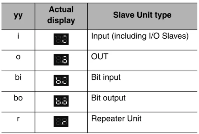
i** (Word Input Slave Units) → o** (Word Output Slave Units) →
↓
Number of Bit Slave Units
bi** (Bit Input Slave Units) → bo** (Bit Output Slave Units) →
↓ Baud rate
• The baud rate is indicated as follows:
“_0”: 4 Mbps
“_1”: 3 Mbps
“_2”: 1.5 Mbps
“_3”: 93.75 kbps
• The display of the number of connected nodes is the same as when pin 3 on the CompoNet DIP switch is OFF.
2-2 Component Names and Functions
2
CC-Link Communications Section z CC-Link Communications Indicators
Status Displayed
contents Description
Error Initialization error Error code The error code is shown on the display in hexadecimal.
Communications error The error code, node type, and applicable node address are displayed in order.
Error code (2-digit hexadecimal) → Slave Unit type →
Node address (3-digit decimal: 100s digit is indicated with 1 bit dot) are displayed in order (for each error cause).
Note: Error codes are different for inputs and outputs.
Example Error code Slave Unit type
Display Display appearance
Display Display appearance
Meaning
Communications error
d9 i IN
o OUT
bi Bit Input
Unit
bo Bit Output
Unit
r Repeater
Unit Node address
duplication
d0 Same as above.
Verification error:
Slave Unit missing.
d5 Same as above.
Verification error:
Unregistered Slave Unit
d6 Same as above.
Operating error Note: “Operating errors”
are all errors except for com- munications errors that occur during Unit oper- ation.
Error code The error code is shown on the display in 2-digit hexadecimal.
Example Error code ---
Display Display appearance Illegal
registration table
E8 ---
Indicator Status Status definition
L RUN Lit green CC-Link data links are active.
Not lit Communications for CC-Link data links have been interrupted.
L ERR Lit red • A CC-Link data link communications error has occurred or the baud rate of the Gateway Unit is different from the baud rate of the CC-Link Master Unit.
• The station number switch is set out of range.
Flashing red The setting of the baud rate DIP switch or station number switch was changed while power was ON.
SD Lit yellow Data is being transmitted normally.
Not lit No data is being transmitted.
RD Lit yellow Data is being received normally.
Not lit No data is being received.
2 - 8
Description of Gateway Unit
CompoNet Gateway Unit for CC-Link Operation Manual
2-2-2 Switch Settings
2
2-2-2 Switch Settings
CompoNet Communications Section z Mode Switch
This switch sets the communications mode number for the Gateway Unit. It is set to between 0 and 6 on a decimal rotary switch. The expanded cyclic setting (a network parameter set with the GX-Developer) in the station information must be set according to the communications mode as shown below.
Note: Do not set communications mode numbers 7 to 9. They are reserved.
Mode
number Name Connectable node
addresses Control points
CC-Link version and expanded cyclic
setting 0
(default)
Communications mode 0
Word Slave Unit: IN0 to IN63 and OUT0 to OUT63 Bit Slave Unit: IN0 to IN127 and OUT0 to OUT127
Word Slave Unit: 1,024 inputs and 1,024 outputs Bit Slave Unit: 256 inputs and 256 outputs
Version 2, octuple (default)
1 Communications
mode 1
Word Slave Unit: IN0 to IN31 and OUT0 to OUT31 Bit Slave Unit: IN0 to IN95 and OUT0 to OUT95
Word Slave Unit: 512 inputs and 512 outputs Bit Slave Unit: 192 inputs and 192 outputs
Version 2, quadruple
2 Communications
mode 2
Word Slave Unit: IN0 to IN15 and OUT0 to OUT15 Bit Slave Unit: IN0 to IN47 and OUT0 to OUT47
Word Slave Unit: 256 inputs and 256 outputs Bit Slave Unit: 96 inputs and 96 outputs
Version 2, double
3 Communications
mode 3
Word Slave Unit: IN0 to IN7 and OUT0 to OUT7 Bit Slave Unit: IN0 to IN15 and OUT0 to OUT15
Word Slave Unit: 128 inputs and 128 outputs Bit Slave Unit: 32 inputs 32 outputs
Version 1
4 Communications
mode 4
Word Slave Unit: IN0 to IN63 and OUT0 to OUT63 Bit Slave Unit: IN0 to IN127 and OUT0 to OUT127
Word Slave Unit: 1,024 inputs and 1,024 outputs Bit Slave Unit: 256 inputs and 256 outputs
Version 2, quadruple
5 Communications
mode 5
Word Slave Unit: IN0 to IN31 and OUT0 to OUT31 Bit Slave Unit: IN0 to IN95 and OUT0 to OUT95
Word Slave Unit: 512 inputs and 512 outputs Bit Slave Unit: 192 inputs and 192 outputs
Version 2, double
6 Communications
mode 6
Word Slave Unit: IN0 to IN15 and OUT0 to OUT15 Bit Slave Unit: IN0 to IN47 and OUT0 to OUT47
Word Slave Unit: 256 inputs and 256 outputs Bit Slave Unit: 96 inputs and 96 outputs
Version 1
7 to 9 Reserved --- --- ---
2-2 Component Names and Functions
2
z DIP Switch
• Baud Rate Setting
The CompoNet Slave Units will automatically detect and use the baud rate that is set on pin 1 (DR0) and pin 2 (DR1). Setting the baud rate is not necessary for any of the Slave Units.
• Details of Connected Nodes
If pin 3 (DCN) is turned ON, details on the connected nodes (baud rate, total number of connected nodes, numbers of I/O Word Slave Units, and numbers of I/O Bit Slave Units) will be displayed on the seven-segment display. If pin 3 is turned OFF, only the total number of connected nodes will be displayed.
Refer to 2-2-1 Indications for information on the displays for the details of connected nodes.
• Registration Table Enable Setting
If pin 4 (REGS) is ON, the registration table that was created with the REGIST CompoNet setting button will be enabled when the power supply is turned ON. Only registered Slave Unit will partici- pate in the network. Registered Slave Units will be compared with the connected Slave Units. If they do not agree, the Registration Table Verification Error Flag at status bit 01 will turn ON.
Refer to 4-1-2 Confirming Normal Slave Unit Operation in Communications Modes 0 to 3 for infor- mation on the registration table.
z CompoNet Setting Buttons (REGIST and RESET Buttons)
• REGIST Button
If the REGIST Button is pressed for at least 2 seconds while pin 4 on the DIP switch is OFF, the Slave Unit configuration that is currently connected to the CompoNet network will be registered in the registration table.
The REGS indicator will flash while the table is being created and then light when creating the table has been finished.
• RESET Button
If the RESET Button is pressed for at least 2 seconds, the Gateway Unit will be reset.
To enable the registration table that was created with the REGIST button, turn ON the registration table enable setting (pin 4) and reset the Gateway Unit.
Pin 1 Pin 2
Description
DR0 DR1
OFF OFF 4 Mbps (default)
ON OFF 3 Mbps
OFF ON 1.5 Mbps
ON ON 93.75 kbps
Pin Name ON OFF
3 Details of Connected Nodes (DCN)
Details of the connected nodes will be displayed.
The total number of connected nodes will be displayed.
Pin Name ON OFF
4 Registration Table Enable Setting (REGS)
Registration table enabled. Registration table disabled.
1 2 3 4
O N
2 - 10
Description of Gateway Unit
CompoNet Gateway Unit for CC-Link Operation Manual
2-2-2 Switch Settings
2
Supplemental Information
To press the CompoNet setting buttons, open the cover as shown below.
CC-Link Communications Section z Station Number Switch
The station number switch sets the station number of the Gateway Unit on the CC-Link network.
z Baud Rate DIP Switch
The baud rate DIP switch sets the baud rate of the Gateway Unit on the CC-Link network.
Set the baud rate of the Gateway Unit to the same value as the CC-Link Master Unit.
• Baud Rate Setting
*1 Always leave pin 4 turned OFF. It is reserved.
Number Description Remarks
1 to 61 Set the station number of the Gateway Unit on the CC-Link network.
Default: 00
0 or 62 to 99 Do not set. The L ERR indicator will light.
Pin 1 Pin 2 Pin 3 Pin 4*1 Baud rate
OFF OFF OFF OFF 156 kbps (default)
OFF OFF ON OFF 625 kbps
OFF ON OFF OFF 2.5 Mbps
OFF ON ON OFF 5 Mbps
ON OFF OFF OFF 10 Mbps
Open from here.
X 1 0 X 1
1 2 3 4
O N
2-2 Component Names and Functions
2
2-2-3 Terminal Arrangement
Gateway Unit/Communications Power Connector
This connector supplies power to the Gateway Unit.
Depending on the type of communications cable that is used for CompoNet, it also supplies power to Slave Units and Repeater Units on the trunk line connected to the CompoNet communications connec- tor.
CompoNet Communications Connector
Note: BS − and BS + terminals output the communications power that is supplied from the power connector. (They also supply power to Slave Units and Repeater Units on the trunk line.)
CC-Link Communications Connector
*1 Insert terminating resistance at the last station.
*2 SLD and FG are connected inside the Unit.
Terminal
name Signal type Signal line color
DA Signal line Blue*1
DB Signal line White*1
DG Communications ground Yellow
SLD*2 Communications cable shield ---
FG*2 Frame ground ---
− (0 V) + (24 VDC)
BS − (communications power negative side)
BS + (communications power positive side) BDL (communications data low)
BDH (communications data high)
2 - 12
Description of Gateway Unit
CompoNet Gateway Unit for CC-Link Operation Manual
2-2-4 Dimensions
2
2-2-4 Dimensions
L L RUN ERR RD
SD
RD
REGISTRESET REG SD NS MS
STATION No.
X10X1 B.RATE MODE DR0
DR1 DCN DA REGS
DB DG SLD FG DC24V INPUT
GQ-CRM21
1 2 4
Mounting Hole Dimensions (mm)
(Unit: mm) Two, 4.2 dia. or M4
25 50
52.9
95
88±0.2
32.5 37.9
2-2 Component Names and Functions
2
3
Wiring and Settings
3-1 Overview of Operating Procedures... 3-1 3-2 Installation Method ... 3-4 3-3 Wiring... 3-5 3-4 Wiring the Power Supply ... 3-6 3-5 Wiring the CompoNet Network... 3-10 3-6 Wiring the CC-Link Network ... 3-11 3-7 Communications Settings ... 3-13
3-1 Overview of Operating Procedures
3
3-1 Overview of Operating Procedures
3-1-1 Basic Startup Procedures
The basic steps required to use the Gateway Unit are given below.
Network Wiring and Power Supply Wiring
• Use the special CC-Link cables.
• Use compliant cables for CompoNet.
▼
Use the station number switch in the CC-Link communications section to set the station number of the Gateway Unit on the CC-Link network.
▼
Use pins 1 to 3 on the baud rate DIP switch in the CC-Link communications section to set the baud rate of the CC-Link network.
Set the baud rate of the Gateway Unit to the same value as the CC-Link Master Unit.
Use pin 1 (DR0) and pin 2 (DR1) on the CompoNet DIP switch to set the baud rate of the CompoNet network.
▼
Select the communications mode based on the system response speed and number of CompoNet Slave Units that are connected.
▼
▼
The CompoNet system will start and the number of CompoNet Slave Units that are connected will be displayed on the seven-segment display on the Gateway Unit.
If pin 3 (DCN) on the CompoNet DIP switch is turned ON, detailed connection information will be displayed.
▼
1) Mounting and Wiring Refer to 3-2 to 3-6.
2) Setting the Station Number Refer to 2-2-2.
3) Setting the Network Baud Rate Refer to 2-2-2.
4) Setting the Communications Mode Refer to 2-2-2.
5) Setting the Node Addresses of the CompoNet Slave Units
6) Power Application
3 - 2
Wiring and Settings
CompoNet Gateway Unit for CC-Link Operation Manual
3-1-1 Basic Startup Procedures
3
Set up the Gateway Unit using the network parameters and write the parameters to the PLC.
▼
• Confirming CC-Link Network Communications ---Refer to 2-2-2.
Check the communications status using the indicators and displays on the CC-Link Master Unit and Gateway Unit.
• Confirming Participation of CompoNet Slave Units ---Refer to 4-1-2.
Check the Participation Flags. ---Refer to 4-1-3.
If the registration table is being used, also check
the Registration Table Verification Error Flag. ---Refer to 4-1-3.
▼
7) Settings from the GX-Developer ---Refer to 3-7-2.
8) Confirming Operation
9) Operation
3-1 Overview of Operating Procedures
3
3-1-2 Procedure for Using the Registration Table
Use the following procedure to register the CompoNet Slave Units in the registration table.
1. Turn OFF pin 4 (REGS) on the CompoNet DIP switch and press the REGIST CompoNet setting button for at least 2 seconds.
The Slave Unit configuration in the CompoNet system will be registered in the registration table.
2. Turn ON pin 4 (REGS) on the CompoNet DIP switch.
3. Press the RESET CompoNet setting button for at least 2 seconds.
The Gateway Unit will be reset and the registration table will be enabled.
Precautions for Correct Use
When using a communications mode between 4 to 6, start the Gateway Unit in the communica- tions mode between 0 and 2 that has the same number of control points, confirm participation of the CompoNet Slave Units, and then register the CompoNet Slave Units.