New focusing mirror system for synchrotron radiation infrared beamlines
S.-J. Chen,MEMBER SPIE
National Cheng Kung University Department of Engineering Science Tainan 701, Taiwan
E-mail: [email protected]
C. K. Kuan S. Y. Perng D. J. Wang H. C. Ho T. C. Tseng Y.-C. Lo C. T. Chen
Synchrotron Radiation Research Center Hsinchu 300, Taiwan
Abstract. A new Kirkpatrick-Baez-type focusing mirror system for use in synchrotron radiation IR beamlines is designed and fabricated. This mir- ror system, which contains two fifth-order-polynomial-corrected cylindri- cal mirrors, can collect and focus the long arc shape IR source from the bending magnet into a nearly perfect point image. To fabricate these two uncommon mirrors, 17-4 PH type stainless steel substrates are chosen and mechanically bent from planar to the desired fifth-order-polynomial- corrected cylindrical shapes with central radii of 3.74 and 5.43 m. The root mean square (rms) roughness and the slope error of these two mirrors are measured to be 0.3 nm and less than 6.3rad, respectively.
The method for calculating the polynomial coefficients of both mirrors as well as the mirror fabrication process, mechanical design, and the method for adjusting the mirror shape using a long trace profiler are presented. © 2004 Society of Photo-Optical Instrumentation Engineers.
[DOI: 10.1117/1.1813438]
Subject terms: high-order polynomial shape; bendable mirrors; infrared beamline;
long trace profiler; optical metrology.
Paper 030474 received Sep. 25, 2003; revised manuscript received May 6, 2004;
accepted for publication Jun. 4, 2004.
1 Introduction
The hundredfold brighter infrared 共IR兲 radiation from a synchrotron storage ring as compared to that from a con- ventional blackbody source has recently opened up new scientific opportunities in the field of IR research.1–3 To establish an advanced IR spectromicroscopy facility in Tai- wan, an IR beamline that collects 70⫻35 mrad IR from the synchrotron bending magnet was designed and is under construction at the Synchrotron Radiation Research Center 共SRRC兲. To achieve as high as possible the performance of the IR beamline, several instrumentation developments are on going, which include a new B-chamber with an enlarged aperture, an internally water-cooled plane mirror for filter- ing out high-energy radiation, highly stable mirror manipu- lators, an off-axis collimating mirror box, and most impor- tantly, a new Kirkpatrick-Baez 共K-B兲-type mirror system for collecting and focusing the IR from the bending mag- net. In this paper, we present the design and fabrication of this new K-B-type focusing mirror system.
2 Optical Layout
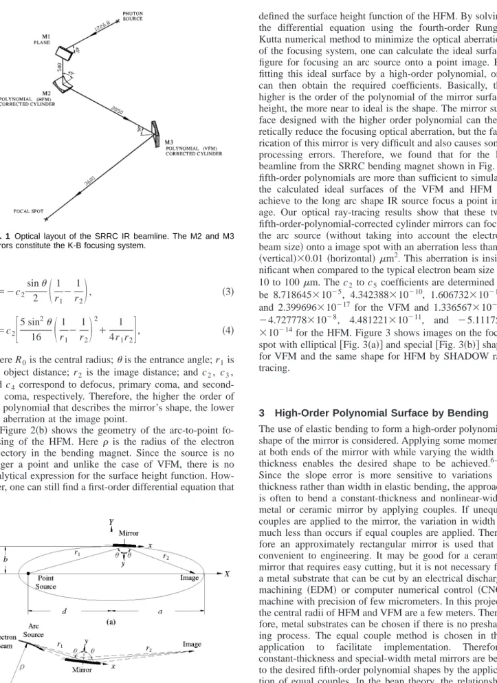
In most of the previous designs, the focusing mirror system of a synchrotron radiation IR beamline contains only one ellipsoidal mirror, and therefore, suffers from the optical aberration caused by the long arc shape IR source from the synchrotron bending magnet. This optical aberration can be removed only by using a multimirror system, such as that of K-B. In the K-B design, two mirrors whose reflecting surfaces are placed perpendicular to each other are utilized to focus the beam in the two orthogonal planes independently.4,5 Figure 1 shows the optical layout of the SRRC IR beamline. The internally water-cooled M1 plane mirror, which intersects the photon beam at 45°, is used to
filter out most of the high-energy photons while allowing IR to be reflected downward. The M2共horizontal focusing mirror, HFM兲 and M3 共vertical focusing mirror, VFM兲 are the two high-order-polynomial-corrected cylindrical mir- rors of the K-B system. The HFM and VFM focus the IR beam from the source onto the focal spot, in the horizontal and vertical planes, respectively. In this beamline design, the IR beam from the source is reflected downward by the M1 mirror intentionally to lower the altitude of the HFM and the VFM, thus reducing ground vibration problems.
Since the IR source is the synchrotron radiation from a bending magnet, the source can be viewed as a point in the vertical plane and an arc in the horizontal plane 共without considering the electron beam size兲. It is well known that the ideal shape for the VFM reflecting surface is the ellip- tical cylinder that can focus tangentially a point source onto a point image共with no focusing effect in the saggital direc- tion兲. To facilitate the analysis of bending an elliptical shape from a planar substrate, it is more convenient to ex- press the surface height function y (x) by a high-order poly- nomial关see Eq. 共1兲兴. Figure 2共a兲 shows the geometry of an elliptical cylinder mirror. By using a power series expan- sion and a coordinate transform, one can obtain all the co- efficients of the polynomial.6 The analytical expression of first three nonvanishing coefficients are given in Eq.共2兲 to 共4兲.
y共x兲⫽c2x2⫹c3x3⫹c4x4⫹¯, 共1兲
c2⫽ 1
2R0⫽cos
4 冉r11⫹r12冊, 共2兲
c3⫽⫺c2
sin
2 冉r11⫺r12冊, 共3兲
c4⫽c2冋5 sin162冉r11⫺r12冊2⫹4r11r2册, 共4兲
where R0is the central radius;is the entrance angle; r1is the object distance; r2 is the image distance; and c2, c3, and c4 correspond to defocus, primary coma, and second- ary coma, respectively. Therefore, the higher the order of the polynomial that describes the mirror’s shape, the lower the aberration at the image point.
Figure 2共b兲 shows the geometry of the arc-to-point fo- cusing of the HFM. Here is the radius of the electron trajectory in the bending magnet. Since the source is no longer a point and unlike the case of VFM, there is no analytical expression for the surface height function. How- ever, one can still find a first-order differential equation that
defined the surface height function of the HFM. By solving the differential equation using the fourth-order Runge- Kutta numerical method to minimize the optical aberration of the focusing system, one can calculate the ideal surface figure for focusing an arc source onto a point image. By fitting this ideal surface by a high-order polynomial, one can then obtain the required coefficients. Basically, the higher is the order of the polynomial of the mirror surface height, the more near to ideal is the shape. The mirror sur- face designed with the higher order polynomial can theo- retically reduce the focusing optical aberration, but the fab- rication of this mirror is very difficult and also causes some processing errors. Therefore, we found that for the IR beamline from the SRRC bending magnet shown in Fig. 1, fifth-order polynomials are more than sufficient to simulate the calculated ideal surfaces of the VFM and HFM to achieve to the long arc shape IR source focus a point im- age. Our optical ray-tracing results show that these two fifth-order-polynomial-corrected cylinder mirrors can focus the arc source 共without taking into account the electron beam size兲 onto a image spot with an aberration less than 1 共vertical兲⫻0.01 共horizontal兲m2. This aberration is insig- nificant when compared to the typical electron beam size of 10 to 100m. The c2 to c5 coefficients are determined to be 8.718645⫻10⫺5, 4.342388⫻10⫺10, 1.606732⫻10⫺12, and 2.399696⫻10⫺17 for the VFM and 1.336567⫻10⫺4,
⫺4.727778⫻10⫺8, 4.481221⫻10⫺11, and ⫺5.111753
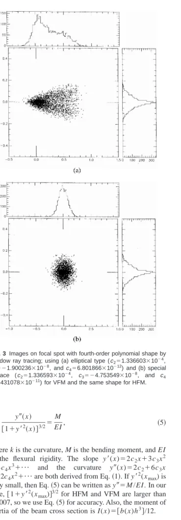
⫻10⫺14for the HFM. Figure 3 shows images on the focal spot with elliptical关Fig. 3共a兲兴 and special 关Fig. 3共b兲兴 shape for VFM and the same shape for HFM by SHADOW ray tracing.
3 High-Order Polynomial Surface by Bending The use of elastic bending to form a high-order polynomial shape of the mirror is considered. Applying some moments at both ends of the mirror with while varying the width or thickness enables the desired shape to be achieved.6 –11 Since the slope error is more sensitive to variations in thickness rather than width in elastic bending, the approach is often to bend a constant-thickness and nonlinear-width metal or ceramic mirror by applying couples. If unequal couples are applied to the mirror, the variation in width is much less than occurs if equal couples are applied. There- fore an approximately rectangular mirror is used that is convenient to engineering. It may be good for a ceramic mirror that requires easy cutting, but it is not necessary for a metal substrate that can be cut by an electrical discharge machining 共EDM兲 or computer numerical control 共CNC兲 machine with precision of few micrometers. In this project, the central radii of HFM and VFM are a few meters. There- fore, metal substrates can be chosen if there is no preshap- ing process. The equal couple method is chosen in this application to facilitate implementation. Therefore, constant-thickness and special-width metal mirrors are bent to the desired fifth-order polynomial shapes by the applica- tion of equal couples. In the bean theory, the relationship between the applying moment and the desired curvature with respect to the neutral axis, can be expressed by the equation
Fig. 1 Optical layout of the SRRC IR beamline. The M2 and M3 mirrors constitute the K-B focusing system.
Fig. 2 Geometry of (a) point-to-point focusing of the VFM and (b) arc-to-point focusing of the HFM.
k⫽ y
⬙
共x兲关1⫹y
⬘
2共x兲兴3/2⫽MEI, 共5兲
where k is the curvature, M is the bending moment, and EI is the flexural rigidity. The slope y
⬘
(x)⫽2c2x⫹3c3x2⫹4c4x3⫹¯ and the curvature y
⬙
(x)⫽2c2⫹6c3x⫹12c4x2⫹¯ are both derived from Eq. 共1兲. If y
⬘
2(xmax) is very small, then Eq.共5兲 can be written as y⬙
⫽M/EI. In our case, 关1⫹y⬘
2(xmax)兴3/2 for HFM and VFM are larger than 1.0007, so we use Eq.共5兲 for accuracy. Also, the moment of inertia of the beam cross section is I(x)⫽关b(x)h3兴/12.Although the bending moment is applied by a constant force F at the end of an arm with length l, the moment is not constant and can be expressed as
M共x兲⫽F兵l⫺关ymax⫺y共x兲兴其, 共6兲
when the beam reaches equilibrium. Usually, ymaxcan be considered to be the maximum sag of the shape. Setting the moment according to Eq.共6兲, the most damaging slope er- ror from the tensile force is theoretically eliminated. Sub- stituting M (x) and I(x) into Eq.共5兲, we can write the new equation
y
⬙
共x兲关1⫹y
⬘
2共x兲兴3/2⫽M共x兲EI共x兲⫽12F兵l⫺关ymax⫺y共x兲兴其
Eb共x兲h3 . 共7兲 Therefore, the variation of mirror width for a high-order polynomial shape is obtained:
b共x兲⫽12F兵l⫺关ymax⫺y共x兲兴其关1⫹y
⬘
2共x兲兴3/2Eh3y
⬙
共x兲 . 共8兲Next, assume that we set the central width of the mirror b(0)⫽b0. The force applied at the end of arm can then be derived from Eq.共8兲 and expressed as
F⫽ b0c2Eh3
6共l⫺ymax兲. 共9兲
Finally, inserting Eq. 共9兲 into Eq. 共10兲, the polynomial width of the mirror under the application of equal couples to produce a high-order polynomial shape is
b共x兲⫽2b0c2关1⫹y
⬘
2共x兲兴3/2关l⫺ymax⫹y共x兲兴y
⬙
共x兲共l⫺ymax兲 . 共10兲The preceding equations can be accurate to use with the following design considerations:
1. Choose the mirror substrate depending on specifica- tions such as the radius and roughness.
2. Decide the central width of the mirror to obtain a clear aperture for the photon beam. Equation共10兲 is a useful equation for a mirror with central radius of less than 10 m and a length of more than 200 mm.
3. Choose a suitable thickness to overcome the effect of gravity. Usually, the thickness shall be at least 5 mm for metal substrate and 10 mm for quartz.
4. Calculate the force from Eq. 共9兲, and then the strength of the mechanism.
5. Use a CNC machine to cut the mirror width with respect to the x coordinate according to Eq.共10兲. This approach is similar to the original one of Underwood,6 but the biggest difference is the more accurate mirror width function derived in Eq.共10兲.
4 Flat Mirror Fabrication
17-4 PH stainless steel is the only metal substrate to be polished to 2 to 3 Å root mean square共rms兲 without elec- troless nickel plating.12,13When the metal mirror with elec-
Fig. 3 Images on focal spot with fourth-order polynomial shape by shadow ray tracing; using (a) elliptical type (c2⫽1.336603⫻10⫺4, c3⫽⫺1.900236⫻10⫺8, andc4⫽6.801866⫻10⫺12) and (b) special surface (c2⫽1.336593⫻10⫺4, c3⫽⫺4.753549⫻10⫺8, and c4
⫽4.431078⫻10⫺11) for VFM and the same shape for HFM.
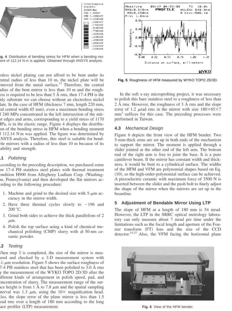
troless nickel plating can not afford to be bent under its central radius of less than 10 m, the nickel plate will be removed from the metal surface.13 Therefore, the central radius of the bent mirror is less than 10 m and the rough- ness is required to be less than 5 Å rms, then 17-4 PH is the only substrate we can choose without an electroless nickel plate. In the case of HFM共thickness 7 mm, length 220 mm, and central width 65 mm兲, even a maximum bending stress of 240 MPa concentrated in the left intersection of the mir- ror edges and arms, corresponding to a yield stress of 1170 MPa, is in the elastic range. Figure 4 displays the distribu- tion of the bending stress in HFM when a bending moment of 112.14 N m was applied. The figure was determined by ANSYS analysis. Therefore, this steel is suitable for bend- able mirrors with a radius of less than 10 m because of its stability and strength.
4.1 Polishing
According to the preceding description, we purchased some raw 17-4 PH stainless steel plates with thermal treatment condition H900 from Allegheny Ludlum Corp. 共Washing- ton, Pennsylvania兲 and then developed the flat mirrors ac- cording to the following procedure:
1. Machine and grind to the desired size with 5-m ac- curacy in the mirror width.
2. Have three thermal cycles slowly to ⫺196 and 200 °C.
3. Grind both sides to achieve the thick parallelism of 2
m.
4. Polish the top surface using a kind of chemical me- chanical polishing 共CMP兲 slurry with 50-nm ce- ramic powder.
4.2 Testing
When step 3 is completed, the size of the mirror is mea- sured and checked by a 3-D measurement system with 0.1-m resolution. Figure 5 shows the surface roughness of 17-4 PH stainless steel that has been polished to 3.0 Å rms by the measurement of the WYKO TOPO 2D/3D after the different kinds of arrangement in polish speed, pad, and concentration of slurry. The measurement range of the sur- face height is from 1 Å to 7.8m and the spatial sampling interval was 1.3 m, using the 10⫻ magnification head.
Also, the slope error of the plane mirror is less than 1.5
rad rms over a length of 180 mm according to the long trace profiler共LTP兲 measurement.
In the soft x-ray microprobing project, it was necessary to polish this bare stainless steel to a roughness of less than 2 Å rms. However, the roughness of 3 Å rms and the slope error of 1.2 rad rms in the mirror with size 180⫻65⫻7 mm3 suffices for this case. The preceding processes were performed in Taiwan.
4.3 Mechanical Design
Figure 6 depicts the front view of the HFM bender. Two 5-mm-thick arms are set up in both ends of the mechanism to support the mirror. The moment is applied through a slider jointed at the other end of the left arm. The bottom end of the right arm is free to joint the base. It is a pure cantilever beam. If the mirror has constant width and thick- ness, it would be bent to a cylindrical surface. The widths of the HFM and VFM are polynomial shapes based on Eq.
共10兲, so the high-order-polynomial surface can be achieved.
A piezoelectric ceramic with maximum force of 3500 N is inserted between the slider and the push bolt to finely adjust the shape of the mirror when the mirrors are set up in the beamline.
5 Adjustment of Bendable Mirror Using LTP The slope of HFM at a length of 180 mm is 54 mrad.
However, the LTP in the SRRC optical metrology labora- tory can only measure about 7 mrad per time under the limitations such as the focal length and aperture of the Fou- rier transform 共FT兲 lens and the size of the CCD detector.14,15 Also, the VFM facing the horizontal plane
Fig. 4 Distribution of bending stress for HFM when a bending mo- ment of 112.14 N m is applied. Obtained through ANSYS analysis.
Fig. 5 Roughness of HFM measured by WYKO TOPO 2D/3D.
Fig. 6 View of the HFM bender.
must be measured by the horizontal scanning LTP to elimi- nate the effect of gravity. Before adjusting the bending mir- ror, we discuss the measurement of the large slope and an easy method of the simply perform a horizontal scan.
5.1 Measurement of Large Slope
Within the limitations of the LTP, without changing the hardware, the only way to measure the large slope is to link separate measurements of several sections. For example, the HFM is measured in nine sections. The overlap area between two sections is 5 mm for purposes of linking. Us- ing the curve-fitting method enables us to adjust the tilting volume and finely tune the overlap area to minimize the measurement error. The mirror can be adjusted to desired shape according to the nine-section slope data linked in sequence over the whole mirror. Even if this method neg- ligibly increases the measurement error of the system, it takes about 3 h to obtain these raw slope data and link them together. Here we describe another method. Herein, the old FT lens is replaced with a new one of focal length of 350 mm 共instead of the original 1250 mm兲 and a diameter of 38.1 mm共instead of the original 25.4 mm兲 and set a new image distance equal to 350 mm using a reflective mirror.
The measurement accuracy of the original system is up to 0.6 rad 共0.4 rad from the hardware limitation and 0.2
rad from the environment兲, so the accuracy of the new system is less than 1.8 rad 共0.4⫻1250/350⫹0.2兲. Under this condition, the measurement range increases from 7 to 30 mrad. The new system simply measures data from two sections and links them together for the whole mirror.
5.2 Horizontal Scan
The optical head and penta prism must be turned to an angle of 90 deg to measure the facing-horizontal mirror.
Then, 2 h are required for the system to stabilize. Here we use a faster and easier method: we just add one more penta prism below the original one and set it to face the test mirror. The laser beams are turned downward by an angle of 90 deg when they pass through the first penta prism. The newly added second prism forces the beams to travel in the horizontal direction to reach the horizontal test mirror. As the laser beams hit the test mirror, they are reflected back to the FT lens through the second and first panta prisms in that order. Through some testing and calibration, we find that the accuracy 共i.e., stability and repeatability兲 of the LTP does not suffer observably.
5.3 Procedure of Adjustment
Equation 共10兲 is a more accurate width function, as men- tioned previously. However, the tolerance of manufacture, uncertainty of the mechanism, and the approximate error of the beam theory approach will contribute some imperfec- tions to the surface of the mirror. Also, mechanical adjust- ment of the bendable mirrors is due only to the bending force, so a workable procedure to adjust the measured slope ym
⬘
(x) to approach the desired slope y⬘
(x) by the LTP is required. A function of the bending error Smd(x) as the difference between the measured slope and the desired slope can be defined asSmd共x兲⫽ym
⬘
共x兲⫺y⬘
共x兲. 共11兲According to the bending mechanism and Eq.共11兲, the pro- cedure for off-line adjustment is
1. Measure data sets by the LTP.
2. Use curve fitting to link them.
3. Observe the error function from Eq.共11兲.
4. Set a minimum the criterion as the root mean square of Eq.共11兲. If the slope error is below the criterion, then stop the procedure. Otherwise, go to the next step.
5. Obtain the derivative of Eq. 共11兲 to obtain a new mirror width.
6. Machine to the new width by CNC or EDM.
7. Run the next cycle if it is necessary.
The procedure is used repeatedly until the slope error satisfies the criterion. According to the experiment and measurement, the slope error and roughness of the flat mir- ror remain unchanged after cutting by the CNC machine.
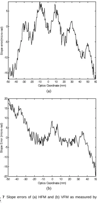
Fig. 7 Slope errors of (a) HFM and (b) VFM as measured by the LTP.
Therefore, the width of the mirror can be finely tuned sev- eral times, by about 1 mm each time until it is wider than the clear aperture of the photon beam on the mirror surface.
After the mirrors are thus bent, the HFM has a slope error 6.3 rad rms over a 120-mm-long clear aperture and the VFM has a slope error of 5.0 rad rms over the same aperture. The HFM is steeper and more asymmetric than the VFM in the optical layout, so it is more difficult to bend the HFM into the same shape as the VFM. Figure 7 illus- trates the slope errors for the HFM and VFM after running through two cycles.
6 Conclusions
We developed the K-B mirror system including two high- order-polynomial-bendable mirrors in the SRRC IR beam- line to create and adjust more accurately collimating im- ages on the focusing point. The VFM was designed in an elliptical shape and the HFM has an optimal high-order- polynomial shape to focus the horizontal arc source on the point image. Both mirrors with 17-4 PH stainless steel sub- strates are mechanically bent from a plane to the desired fifth-order-polynomial shapes by applying equal couples.
The fabricating process, mechanical design, and method of adjustment of the shape of the mirror using the LTP were all performed in the SRRC. The roughness of the mirror was 3 Å rms and the slope error was below 1.5rad rms over the 180-mm clear aperture. Results presented herein can provide a valuable reference for developing bent mir- rors for the x-ray microprobing project.
Acknowledgments
This study was partially supported by the National Science Council, Taiwan, under Grant No. NSC 89-2112-M-213- 005.
References
1. G. P. Williams, ‘‘Infrared synchrotron radiation instrumentation and applications,’’ Rev. Sci. Instrum. 63共1兲, 1535–1538 共1992兲.
2. M. Shleifer, E. Smith, and G. P. Williams, ‘‘Manually and remotely operated ultra-high-vacuum double-axis mirror manipulators for the
infrared beamline at the NSLS,’’ Nucl. Instrum. Methods Phys. Res. A 266, 402– 403共1988兲.
3. G. P. Williams, P. Z. Takacs, R. W. Klaffky, and M. Shleifer, ‘‘The infrared line IR4 at the NSLS,’’ Nucl. Instrum. Methods Phys. Res. A A246, 165–167共1986兲.
4. C. T. Chen and F. Sette, ‘‘Performance of the dragon soft x-ray beam- line,’’ Rev. Sci. Instrum. 60共7兲, 1616–1621 共1989兲.
5. W. B. Peatman, Gratings, Mirrors and Slits, Gordon and Breach Sci- ence Publishers, Amsterdam, Netherlands共1997兲.
6. J. H. Underwood, ‘‘Generation of a parallel x-ray beam and its use in testing collimators,’’ Space Sci. Instrum. 3, 259–270共1977兲.
7. M. R. Howells and D. Lunt, ‘‘Design considerations for adjustable- curvature, high-power, x-ray mirrors based on elastic bending,’’ Opt.
Eng. 32共8兲, 1981–1989 共1993兲.
8. H. A. Padmore, M. R. Howells, S. Irick, T. Renner, and R. Sandler,
‘‘Some new schemes for producing high-accuracy elliptical x-ray mir- rors by elastic bending,’’ Proc. SPIE 2856, 145–156共1996兲.
9. T. R. Renner, K. Franck, M. Howells, S. Irick, H. A. Padmore, and S.-Y. Rah, ‘‘The construction and performance of a meter long ellip- tically bent mirror,’’ Proc. SPIE 3152, 17–26共1997兲.
10. J. H. Underwood, P. J. Batson, R. Beguiristain, and E. M. Gullikson,
‘‘Elastic bending and water cooling strategies for producing high quality synchrotron-radiation mirrors in silicon,’’ Proc. SPIE 3152, 88 –95共1997兲.
11. A. A. MacDowell, R. Celestre, C.-H. Chang, M. R. Howells, S. Lock- lin, H. A. Padmore, R. Patel, and R. Sandler, ‘‘Progress towards sub- micron hard x-ray imaging using elliptically bent mirrors,’’ Proc.
SPIE 3152, 126 –132共1997兲.
12. R. A. Paquin and M. R. Howells, ‘‘Mirror materials for synchrotron radiation optics,’’ Proc. SPIE 3152, 2–16共1997兲.
13. M. R. Howells and J. Casstevens, ‘‘Achievement of a superpolish on bare stainless steel,’’ Proc. SPIE 3152, 35– 40共1997兲.
14. P. Z. Takacs, S.-N. Qian, and J. Colbert, ‘‘Design of a long-trace surface profiler,’’ Proc. SPIE 749, 59– 64共1987兲.
15. S.-N. Qian, H. Li, and P. Z. Takacs, ‘‘Penta-prism long trace profiler 共PPLTP兲 for measurement of grazing incidence space optics,’’ Proc.
SPIE 2805, 108 –114共1996兲.
S.-J. Chen received his BS degree from National Taiwan University in 1987, his MS degree in mechanical engineering from Columbia University in 1991, and his PhD degree for research in adaptive noise cancellation and image restoration at the University of Califor- nia, Los Angeles (UCLA), in 1996. He joined the Synchrotron Ra- diation Research Center in January 1998 to develop soft x-ray ac- tive gratings and microfocusing optical systems. He did most of his work in the field of adaptive optics and its applications. He is cur- rently, an assistant professor with the National Cheng Kung Univer- sity and his principle research includes optical biosensors, adaptive optics, and optomechatronics.
Biographies and photographs of the other authors are not available.