Chapter 5
Tolerating VLR and HLR Failures in Two-Tier PCS Networks
_____________________________________
5.1. The System Description
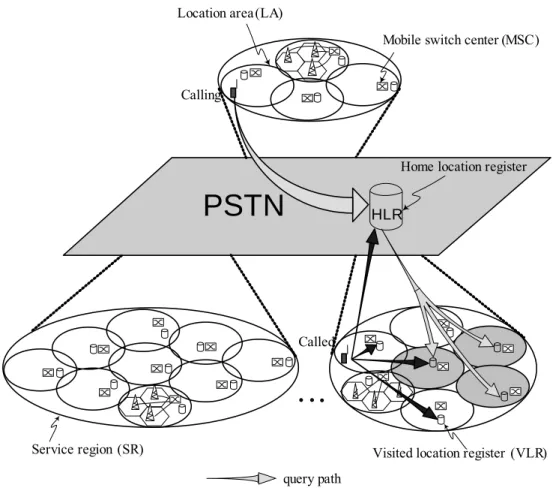
The framework of the system network is shown in Fig. 5-1. The system is modeled as a geographical area that consists of a lot of cells. The cells are aggregated into contiguous geographical regions called location areas (LAs). The mobile node, referred to as the mobile host (MH), is a part of only one cell at a time.
A fixed base station, called the mobile support station (MSS), supports each cell. The
communication between MH and MSS is through radio waves or infrared waves
which are wireless. The mobile support station is static and connected through
dedicated wire-line link to a mobile switch center (MSC). An MSC, which typically
provides switching and can be viewed as a bridge for connecting the wireless
network and the wired network, serves one LA. A visitor location register (VLR) is
maintained at each LA, which stores the temporary records of the current location
information of the MH while it is not at “home”. Several LAs are grouped into a
service region (SR). All the VLRs in one SR are formed as a local fault-tolerant
system, which can tolerate the failures of one or more VLRs. The mechanism of the fault-tolerance will be described in section 5.2 and section 5.3. All MSCs are finally connected to a Public Switched Telephone Network (PSTN) that is a wired backbone network. The system is a two-tier database architecture consisting of a home location register (HLR) and visitor location registers (VLRs). The HLR cooperates with VLRs to track and find the locations of MHs. The information, recorded in the HLR database, can assist the system in finding out the SR where the MH is currently located. Then, the LA where the MH resides is tracked. Furthermore, the VLR in the LA is used to retrieve information for finding out the MSS that servers the MH. The registration information of a MH, which consists of authentication, billing, and all access information, always keeps in the HLR and the current VLR where the MH is
PSTN
HLR Location area (LA)Mobile switch center (MSC)
Visited location register (VLR)
Home location register
Service region (SR) Wireless cell
Mobile support station (MSS)
Fig. 5-1. System architecture.
currently located (the information could be replicated from the previous VLR to the current VLR when the MH moves from one LA to another LA.). Each time when the update or query procedure is processed the authentication request is checked first by the local MSC. If the MH roams to other service region (SR), the access to the HLR is needed. In this case all the information could be synchronized between the local VLR and the HLR in distributed manner. All the MSCs in the system run the network time protocol (NTP). By automating the setting of accurate, synchronized time for all of the MSCs in the network system, the HLR acts as a network time server. By synchronizing with the network time server, the MSCs can keep all of the location tracking processes working properly. In the next section, we will describe the quorum-based approach that will be used in our system design.
5.2 System Design for Location Update
In this section, we use the LegRing scheme described in section 2.4.1 to devise a fault-tolerant location tracking system. In cellular PCS systems, location management is achieved by querying and updating. A query occurs when a host needs to communicate with another mobile host whose location is unexpected, and an update occurs when a mobile host changes its location.
All the coverage areas of the SRs were initially decided by the system. Then, a LegRing algorithm was run and the information of quorum sets was disseminated and recorded on tables in all location servers. Therefore, the system can begin running the quorum-based fault-tolerant updates and queries.
In a traditional location management scheme, an update procedure that would
need to coordinate between HLR and VLRs will occur whenever an MH moves to a new LA. In our approach, when an MH moves to a new LA in the same SR, instead of updating information to the HLR, it merely reports its location to the VLRs of selected quorum in the local SR. We divide the update procedure into two types:
intra-SR update and inter-SR update. When an MH roams to another SR, an inter-SR update procedure will be triggered. By using the user mobility behavior model, we could suitably choose the coverage areas of one SR. Then, with high probability, the users would move around in the same SR. Hence, in most conditions, the update procedures will be handled locally. On the other hand, the quorum-based update procedures will offer a fault-tolerant mechanism for location queries. A detailed description of update procedures will be discussed in the following section.
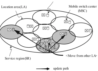
5.2.1 Intra-SR Update
Location area (LA)
Visited location register (VLR)
Service region (SR)
update path
Mobile switch center (MSC)
<Move from other LA>
Fig. 5-2. Intra-SR Update
In the following, we use timestamps, synchronized by the network time server described in section 5.1, with our LegRing location management scheme, defined in Definition 4, to implement the location update algorithms. When a mobile host moves from one LA to others in the same SR, its location information has to be updated locally (Fig. 5-2). Therefore, the following steps are performed as the intra-SR update procedure:
1. The UPDATE message associated with a timestamp is sent to the current MSC which forwards this message to all the VLRs in the default U-quorum (i.e., the U-quorum whose first element is the local VLR) of the SR.
2. Upon receiving the UPDATE message, the VLRs add or overwrite the new location information received to their databases and send back the ACK message.
3. If the procedure does not receive all the ACK messages from all VLRs in the quorum during a given period of time, then it randomly selects another U-quorum, sends the UPDATE message to all VLRs in the new quorum again, and goes to step 2; otherwise, it stops.
By using this quorum-based location update scheme, the newest location information of the MH is stored in some VLRs of the U-quorum. When a MH wishes to communicate with another MH, some VLRs of the Q-quorum are queried.
According to the definition of Legion, the Q-quorum is bound to contain at least one
VLR that belongs to the U-quorum that received the latest update. In fault-tolerant
aspect, if some VLRs of U-quorum or Q-quorum fail, then another U-quorum or
Q-quorum is reselected for the update or query process. Again, any new pair of U-quorum and Q-quorum has at least one common VLR (i.e. the VLR is one element of the intersection of U-quorum and Q-quorum). Hence, the newest location information is extracted from the common VLR(s).
In the IS-41 location management scheme, if the distance between the visited area and the HLR is large, the signaling delay for the location update is long. Our approach, an intra-SR update, is a way to reduce the signaling delay for performing updates. This is especially useful when the MH always moves within a particular SR.
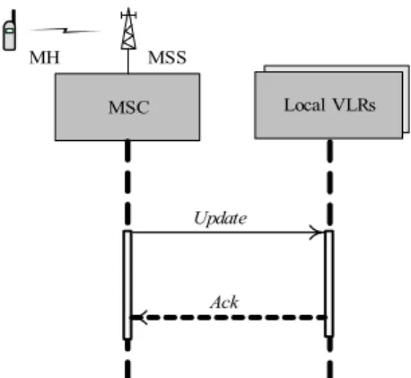
The Unified Modeling Language (UML) diagram of signal flow of intra-SR update is shown in Fig. 5-3.
Local VLRs MSC
Update
Ack
MH MSS
Fig. 5-3. Signal flow of intra-SR update.
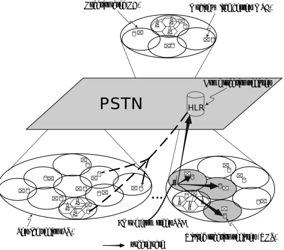
5.2.2 Inter-SR Update
When roaming around the whole network, an MH may go through different SRs.
If an MH enters another SR, an inter-SR update procedure will be triggered (Fig.
5-4). As described in section 2.4.1, we use our quorum-based LegRing scheme to
implement the inter-SR update algorithms. The procedure is described as follows:
PSTN
HLR Location area (LA)Home location register
Service region (SR)
Visited location register (VLR) update path
<Move from other SR>
Mobile switch center (MSC)
-
delete path
Fig. 5-4. Inter-SR update.
1. The UPDATE message associated with a timestamp is sent to the current MSC which forwards this message to all the VLRs in the default U-quorum of the current SR. The procedure concurrently sends the redirected pointer (i.e., a forwarding route information including the SR identifier) associated with the timestamp to the HLR.
2. Upon receiving the UPDATE message, the VLRs add or overwrite the new
information received to their databases and send back the ACK message.
3. If the procedure does not receive all the ACK messages from all VLRs in the selected quorum of the current SR during a given period of time, then it randomly selects another U-quorum, sends the UPDATE message to all VLRs in the new quorum again, and goes to step 2; otherwise, it goes to next step.
4. Upon receiving the redirected pointer, the HLR overwrites the new information received to its database and then issues the NOT_IN message (it means that the MH is not in this SR) associated with the timestamp to the VLRs in the randomly selected U-quorum of the previous SR out of which the MH have moved.
5. Upon receiving the NOT_IN message, the VLRs add or overwrite the new information received to their databases and send back the ACK message to the HLR.
6. If the HLR does not receive all the ACK messages from all VLRs in the selected quorum of the previous SR during a given period of time, then it randomly selects another U-quorum, sends the NOT_IN message to all VLRs in the new quorum again, and goes to step 5; otherwise, it goes to next step.
7. If the HLR receives all the ACK messages from all the VLRs in the selected U-quorum of the previous SR, then the HLR sends back the ACK message.
8. If the procedure dose not receive the ACK message from the HLR during a given period of time, then it resends the redirected pointer to the HLR and goes to step 4; otherwise, it stops.
As described in the above procedure, the VLRs in the selected quorum of the
current SR maintain the id of the current MSC serving the MH. For the HLR, it
maintains the id of the SR where the MH currently resides. When executed, the procedure disseminates the information to the HLR and all the VLRs in the quorum of the current SR. This dissemination is carried out in parallel so that new location information is very quickly updated. The UML diagram of signal flow of the inter-SR update is shown in Fig. 5-5.
5.3 System Design for Location Query
When a mobile host wishes to communicate with another host whose location is unknown, the query procedure is invoked. Again, the fault-tolerant LegRing scheme is used in the location query process. We have designed the query procedure as two types: intra-SR query and inter-SR query, and describe them as follows.
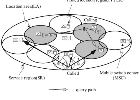
5.3.1 Intra-SR Query
An intra-SR query occurs when the calling and called MH are in the same SR.
Fig. 5-6 shows the intra-SR query path. The procedure is described in the following
HLR
MSC Local VLRs
Update
Ack
MH MSS
Remote VLRs
Update Delete
Ack Ack
Fig. 5-5. Signal flow of inter-SR update.
steps:
Location area (LA)
Visited location register (VLR)
Service region (SR)
query path
Mobile switch center (MSC)
Called
Calling
Fig. 5-6. Intra-SR query.
1. The calling MH sends a QUERY message through the current MSC which forwards this message to all the VLRs in the default Q-quorum of the SR.
2. Upon receiving the QUERY message, the VLR, which has a copy of queried information, sends a REPLY containing the timestamp associated with the queried information. Otherwise, the VLR sends a NULL reply.
3. When all the REPLY messages from all the VLRs in the quorum are received,
the procedure selects the information with the latest timestamp. Since the calling
and called hosts are in the same SR, at least one of the VLRs in the Q-quorum of
the SR has the location information of the called MH. Then, according to the
location information, the call can be connected to the intended MH.
4. If the procedure does not receive all the REPLY messages after a given period of time, then it randomly selects another Q-quorum, sends the QUERY message to all the VLRs in the new quorum again and goes to step 2; otherwise, it stops.
The completion of the intra-SR query procedure is quick, since it is done locally.
Compared to the query in the IS-41 scheme, which accesses the HLR that may be far away from the calling MH, our intra-SR query is more time effective since the access to HLR could involve two long-distance legs. The UML diagram of signal flow of intra-SR query is shown in Fig. 5-7.
5.3.2 Inter-SR Query
If the calling and called host are in different SRs, the communication invokes the inter-SR query procedure. Fig. 5-8 shows the inter-SR query path. The procedure is described as follows:
Local VLRs/MSCs MSC
Query
Ack Paging
P_Ack
Calling MH MSS MSS Called MH
Fig. 5-7. Signal flow of intra-SR query.
PSTN
HLR Location area (LA)Home location register
Service region (SR) Visited location register (VLR)
query path
Mobile switch center (MSC)
Calling
Called
Fig. 5-8. Inter-SR query.
1. The calling MH sends a QUERY message through the current MSC, which forwards this message to all the VLRs in the default Q-quorum of the current SR.
2. When all the REPLY messages from all the VLRs in the selected quorum of the
current SR are received, the procedure selects the message with the latest
timestamp. Since the calling and called MH are at different SRs, the NOT_IN
message would be the message that has the latest timestamp. Then, the HLR is
inquired for the location information of the called MH.
3. If the procedure does not receive all the REPLY messages from all the VLRs in the selected quorum after a given period of time, then it randomly selects another Q-quorum of the current SR, sends the QUERY message to all the VLRs in the new quorum again, and goes to the previous step; otherwise, it goes to next step.
4. According to the redirected pointer in the HLR’s database, the redirected request is sent to all the VLRs in the randomly selected Q-quorum of the SR in which the called MH resides.
5. Upon receiving a QUERY message, the VLR in the randomly selected quorum of the SR, which has a copy of queried information, sends a REPLY containing the timestamp associated with the queried information. Otherwise, the VLR sends a NULL reply.
6. When all the REPLY messages from all the VLRs in the selected quorum of the SR are received, the procedure selects the location information with the latest timestamp. Then, according to the location information, the call request to the called MH can be connected
7. If the procedure does not receive all the REPLY messages from all the VLRs in
the selected quorum after a given period of time, then it randomly selects
another Q-quorum of the SR, sends the QUERY message to all the VLRs in the
new quorum again, and goes to the previous step; otherwise, it stops.
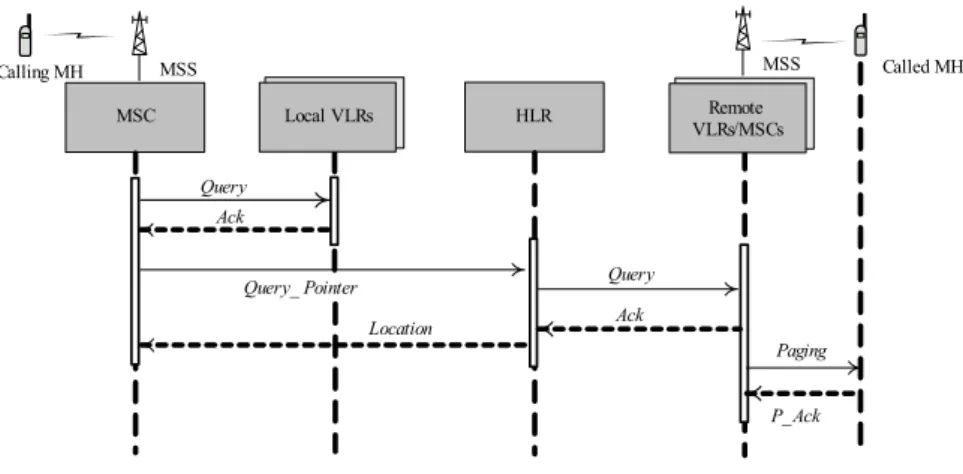
The UML diagram of signal flow of inter-SR query is shown in Fig. 5-9.
According to the query procedures described above, our approach can tolerate the failures of VLRs. Based on the quorum-based LegRing scheme, if some VLRs fail to respond then other VLRs in a new quorum would be selected as substitutions.
Take a system as an example. Assume three service regions SR1, SR2, and SR3 have nine, seven, and four location areas (LAs), respectively. According to Definition 3, the U-set and Q-set are constructed as follows:
In SR1, the U-set and Q-set are
U-set={{0,1,2},{1,2,3},{2,3,4},{3,4,5},{4,5,6},{5,6,7},{6,7,8},{7,8,0},{8,0,1}};
Q-set={{0,3,6},{1,4,7},{2,5,8},{3,6,0},{4,7,1},{5,8,2},{6,0,3},{7,1,4},{8,2,5}};
In SR2, the U-set and Q-set are
U-set={{9,10,11},{10,11,12},{11,12,13},{12,13,14},{13,14,15},{14,15,9},{15,9 ,10}};
Remote VLRs/MSCs
Paging P_Ack
MSS Called MH HLR
MSC Local VLRs
Query Calling MH MSS
Query
Location Ack
Ack
Query_ Pointer
Fig. 5-9. Signal flow of inter-SR query.
Q-set={{9,12,15},{10,13,9},{11,14,10},{12,15,11},{13,9,12},{14,10,13},{15,11 ,14}};
In SR3, the U-set and Q-set are
U-set={{16,17},{17,18},{18,19},{19,16}};
Q-set={{16,18},{17,19},{18,16},{19,17}};
If a mobile host h moves from one LA (#3) to another in the same SR (SR1), new location information should be stored in the local VLRs, for example, register 3, 4 and 5, in the default U-quorum of SR1. When a mobile host h’ in the other LA (#2) of the same SR (SR1) wants to communicate with host h, it can acquire the information from the VLRs, for example, register 2, 5 and 8, in the default Q-quorum of SR1. Since quorum {3,4,5} and {2,5,8} have the common register 5, the newest location information of host h can be extracted through the register 5.
However, if the register 5 failed during the querying period, then h’ can acquire another Q-quorum, for example, register 6, 0, and 3. Since quorum {3,4,5} and {6,0,3} have the common register 3, the newest location information of host h can be extracted through the register 3.
If a mobile host g moves from SR3 to SR2, new location information should be
stored in the local VLRs of SR2, for example, register 9, 10 and 11, and the
redirected pointer is sent to the HLR. Meanwhile, the cancellation (i.e., NOT_IN
message) is sent to the VLRs in the randomly selected U-quorum of SR3, for
example, register 17 and 18. When a mobile host g’ in SR3 wants to communicate
with host g, it first acquires the information from the VLRs, for example, register 19
and 17 in the default Q-quorum of SR3. Since quorum {17,18} and {19,17} have the
common register 17, the latest timestamp with NOT_IN message will be extracted through the register 17. Then, the HLR is inquired for the location information.
According to the redirected pointer in the HLR’s database, the redirected request is sent to all the VLRs, for example, register 12, 15 and 11, in randomly selected Q-quorum of the SR2. Since quorum {9,10,11} and {12,15,11} have the common register 11, the newest location information of the host g can be extracted through the register 11.
5.4 Dealing with the Failure of the HLR
In some accident situations, the HLR may be down for a period of time. In this section we will discuss the approach to deal with the situation when the HLR fails.
During the inter-SR update, if the HLR fails, it will make no response to the reception of the redirected pointer. Then, the inter-SR update process cannot be accomplished. In this situation, instead of waiting for the ACK message from the HLR, the procedure randomly selects an U-quorum of the previous SR, sends the NOT_IN message associated with the timestamp to all the VLRs in the selected quorum of the previous SR, and keeps on sending the redirected pointer to the HLR.
This process will be repeated until the HLR and all the VLRs in the selected quorum of the previous SR send the ACK messages back. Then, the inter-SR is completed.
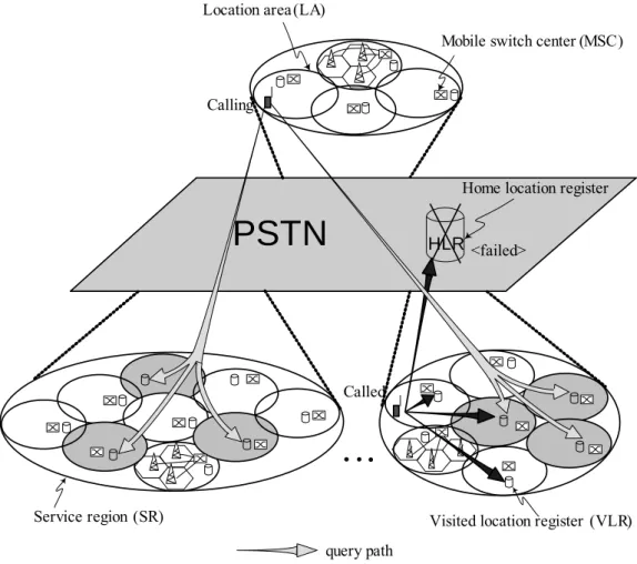
On the other hand, if the HLR is down, then the inter-SR query can not be
performed. When a mobile host wishes to communicate with another host whose
location is not in the same SR, the connection can not be achieved. In this situation,
the procedure is switched to multicast the QUERY message to all the VLRs in the
randomly selected Q-quorum of each SR (Fig. 5-10). After receiving all the REPLY
messages from those VLRs, the procedure will extract the location information with the latest timestamp from one of those VLRs. Then, according to the location information, the call can be connected to the intended MH.
5.5 User Mobility Behavior Model
Similar to section 4.4, we use the same user mobility model, fluid-flow model, for performance analysis. In Wnag and Huey’s paper [41], this model had been used for their region based analysis. Since our scheme is a design of the service region (i.e.
PSTN
HLR Location area (LA)Home location register
Service region (SR) Visited location register (VLR)
query path
Mobile switch center (MSC)
Calling
Called
<failed>
Fig. 5-10. Dealing with the failure of the HLR.
similar to the region based scheme), we also adopt the fluid-flow model as our analytical model. Under the fluid-flow model [40], the direction of an MH’s movement with respect to the border is uniformly distributed in the range of (0,2π) and the density of users is uniform throughout the area. Let v be an MH’s average speed; A and P will be the area and the perimeter of a given area, respectively. The border-crossing rate out of a given area for a single moving user is given by
(35)
We assume the shape of an LA is circular, and then the border-crossing rate for an MH out of an LA is
(36)
The border-crossing rate for an MH out of an SR is
(37)
where r
LAand r
SRare the radius of circular area of the LA and SR, respectively.
An MH that crosses an SR will also cross an LA border. Hence, the border-crossing rate for the MH which stays in the same SR is
(38)
We use an imbedded Markov chain model to describe the location update process of an MH. The state transition diagram for the imbedded Markov chain is given in
2 .
LA
LA
r
v
= ⋅ ε π
2 ,
SR
SR
r
v
= ⋅ ε π
1 ).
( 1 2
SR LA SR
LA
r r
v −
=
−
= ε ε π
ξ
A. P v
⋅
= ⋅
ε π
Fig. 5-11. The resulting state probability of the analysis of this model is similar to [39].
0 H0,1 1 H1,2 2 H2,3 Hk−1,k k Hk k,+1
0 ,
U0
0 ,
U1
0 .
U2
,0
Uk
Fig. 5-11. The state transition diagram.
The state of the imbedded Markov chain, k, is defined as the number of LAs in the same SR, which the MH has passed by. The state transition rate H
k,k+1=ξ(0 ≤ k) represents the MH moving rate from state k to the state k+1, which moves to the neighbor LA in the same SR. And the transition rate U
k,0= ε
SR(0 ≤ k) represents the MH moving rate from state i to state 0, which moves to another LA out of the SR.
Assume p
kto be the equilibrium probability of being in state k of the process. We have
(39)
(40)
The sum of probabilities of all states is equal to one. Hence, we have
(41)
Using the equation (39), (40), and (41), we obtain
, ...) ...( )
( 0 1 2
0 SR p p p pk SR
p
ξ
+ε
= + + + + +ε
. 1
0
∑
∞=
= k
p
k. 1 )
1
p ( k
p
k−ξ =
kξ + ε
SR≤
(42)
(43)
Based on this analytic model, we will analyze the cost for our scheme and basic IS-41 HLR/VLR scheme in the following sections.
It is observed that a mobile user stays within certain geographic areas. By using mobility behavior model, the system could suitably choose the coverage areas of one SR. Therefore, with high probability, the MH would move around in the same SR.
All the coverage areas of the SRs were initially decided according to the analysis before running the update and query procedures. Once the coverage areas of a SR have been decided, all the LAs in the SR were assigned an unique ID and a leader of all the LAs was selected in distributed manner. Then, a LegRing algorithm was run in constant time complexity and the quorum sets were recorded on tables in all location servers. Therefore, the system can begin running the quorum-based fault-tolerant updates and queries.
Since the quorum tables were built initially (but may be rebuilt if the system needs to change the coverage of some SRs in few times), we will not calculate the initial cost for building the quorum tables in our analyses.
We introduce parameters for analyses in the following:
α
l: cost for transmitting a message through the local link within the SR.
α
r: cost for transmitting a message through the remote link.
α
VLR: cost for a query or an update to the VLR.
α : cost for a query or an update to the HLR.
SR LA SR SR
r
p = r
= + ε ξ
ε
0
0 0
0 (1 )
)]
/(
[ p p p
pk =
ξ ξ
+ε
SR k = − k5.6 Performance Analysis for Proposed Scheme
In this section, the evaluations and comparisons of the cost for the proposed scheme and the conventional IS-41 scheme are presented. For a fair reason, we first compare the cost between two schemes based on the condition that there are no access failures to all location registers (LRs) in both schemes. On the other hand, our quorum-based scheme can provide fault tolerance at the expense of increased access cost of LRs. Then, the comparison of the total cost between the proposed scheme with fault tolerance and without fault tolerance will be presented. We assume that the number of SRs is N and each SR has an average of m LAs.
5.6.1 Update Cost
In this section, we will analyze the average update cost for our scheme. The update cost is divided into two parts: intra-SR update cost (the cost for an update procedure when the MH moves within the same SR) and inter-SR update cost (the cost for an update procedure when the MH roams to another SR).
In intra-SR update, a request signal transmitted from the MSC to the VLRs is within the same SR, which has a cost α
l. In addition, there are
mdatabases of VLRs that are updated, where the access cost for each VLR is δ
VLR. Furthermore, the ACK message is transmitted in the local link, which also has a cost α
l.Hence, we have this intra-SR update cost equation
(44)
(2 ).
intra SR
m
l VLRα
−= α α +
In inter-SR update, there is an additional update cost for sending the redirected pointer to the HLR. In addition, cancellation messages are sent to
mVLRs in the previous SR. Thus, the inter-SR update cost is
(45)
Based on the equation (44) and (45), the average update cost of our scheme is
(46)
Let v
ube an independent and identically distributed random variable representing the LA resident time; and we assume v
uto be exponentially distributed with the rate of λ
U. Thus, the average update cost per unit time is
(47)
5.6.2 Query Cost
In this section, we will calculate the query cost for our scheme, which is associated with the hit ratio. The h is assumed to be an intra-SR hit ratio. Let α
hitand α
missbe the query costs of the protocols when there is a hit query (which means the location information is found in the SR where the calling MH currently resides) and a miss query, respectively.
In addition to the cost α
lfor sending a message through each local link, there are
mdatabases of VLRs to be queried, where the cost is α
VLRfor each VLR. Hence, in a hit case, we have a query cost equation
(2 2 2 ) (2 ).
inter SR
m
l r VLR r HLRα
−= α + α + α + α α +
0
1
( ).
Update inter SR intra SR k
k
P kP
α α
−α
− ∞=
= + ∑
U
.
Update
C
U= α λ
(48)
where the α
Pagingis the cost to page a user in a cell.
In the case of a miss, the HLR and the VLRs of the redirected SR are queried.
Therefore, additional costs for sending messages through the remote links, the cost for querying the redirected pointer of the HLR, and costs for access to the databases of the remote VLRs are needed, which have cost α
r, α
HLRand α
VLRfor each remote link, HLR and VLR, respectively. Thus we have a query cost equation of a miss case
(49)
The average query cost α
Queryis then given by
(50)
Let σ
qbe an independent and identically distributed random variable representing the call arrival time; and we assume σ
qto be exponentially distributed with the rate of λ
Q. Thus, the average update cost per unit time is
(2 ) ,
hit m l VLR Paging
α
=α α
+ +α
(2 2 2 )
(2 ) .
miss l r VLR
r HLR Paging
α m α α α
α α α
= + + +
+ +
(1 )
[ (2 ) ]
(1 )[ (2 2 2 ) (2 ) ]
[2 2( 1) 2 ]
[2( 1) ].
Query hit miss
l VLR Paging
l r VLR r HLR Paging
l r VLR HLR Paging
r VLR HLR
h h
h m
h m
m m m
h m m
α α α
α α α
α α α α α α
α α α α α
α α α
= + −
= + + +
− + + + + +
= + + + + +
− + + +
(51)
The total cost per unit time for the proposed scheme is
(52)
5.7 Performance Analysis for IS-41 Scheme
The basic IS-41 HLR/VLR scheme will be compared to our proposed scheme. In the following, the update and query costs for IS-41 scheme will be analyzed. In the IS-41 scheme, the update message is forwarded to the MH’s HLR from the MH’s MSC to update its current location; and the remove message is issued from the HLR to the old VLR to delete the obsolete location information. Next, the remove response message is sent back to the HLR, and the ACK message is then sent to the MH’s MSC. Thus, the average update cost for IS-41 scheme is
(53)
The average update cost per unit time for IS-41 scheme is
(54)
In the IS-41 approach, a query message is transmitted to the HLR to acquire the called MH’s location information; and the routing-request message is issued from
0 1
(4 2 )( ).
Update r VLR HLR k
k
P kP
α α α α
∞=
′ = + + + ∑
U Update U
. C ′ = α ′ λ
Q
.
Query
C
Q= α λ
Proposed U Q
.
C = C + C
HLR to the called VLR. Then, the location information is sent to the calling MSC.
Therefore, the average query cost for IS-41 scheme is
(55)
The average query cost per unit time for IS-41 scheme is
(56)
The total cost per unit time for IS-41 scheme is
(57)
5.8 Numerical Results
The evaluations and comparisons of the cost for the proposed scheme and the conventional IS-41 scheme are presented in this section. We normalize the value of α
lto one for evaluating the cost. The values of the cost ratios of α
l: α
r= 1:5 [39]
and α
l: α
Paging= 1:0.2 [42] are used. Further, we assume the cost ratio of α
VLR: α
HLR= 1:5. Similar to the section 4.9 the call to mobility ratio (CMR) was expressed as the ratio of the call arrival rate to the mobility rate, such as
(58) In [41], the relation between the hit ratio and call to mobility ratio (CMR) was calculated as
(59)
4 2 .
Query r VLR HLR Paging
α ′ = α + α + α + α
41 U Q.
IS C C
C = ′ + ′
Q Query Q. C′ =
α
′λ
. /
UCMR = λ
Qλ
).
1 /( h h CMR= −
Fig. 5-12. Comparisons of average query cost under various CMR.
Fig. 5-12 shows the relation between call to mobility ratio (CMR) and the average query cost for Proposed and IS-41 schemes. Three data sets are considered when α
l: α
VLR= 1:5, 1:10, and 1:15. An average of nine LAs in one SR is assumed.
This figure indicates that by using our proposed scheme the query cost is reduced, if
the CMR ratio is more than one. Since the intra-SR (hit case) queries are quickly
processed locally without inquiring the database of the HLR, the average query cost
and latency can be decreased. This figure illustrates the more CMR ratio we have,
the less query cost we get. For example, when CMR = 10, the query cost of the
proposed scheme is about 50% less than that of the IS-41 scheme.
Fig. 5-13. Comparisons of total cost under various CMR.
In Fig. 5-13, we show the average total cost between our proposed scheme and
the IS-41 scheme under the call to mobility ratio (CMR). Again, an average of nine
LAs in one SR is assumed. According to the state probability P
0, the MH may
mostly move within an SR, and updates are carried out locally (intra-SR update)
without sending the information to the HLR. Since the average update cost can be
reduced and the average query cost is decreased on condition that the CMR is more
than one, as described in Fig. 5-13, the average total cost of the proposed scheme is
less than that of the IS-41 scheme. Especially, when the CMR value is higher than
two, the average total cost is significantly reduced.
Fig. 5-14. Comparisons of average update cost under various LAs.
In Fig. 5-14, the update cost is compared between two schemes under the average
number of LAs in an SR. Again, three data sets are considered when α
l: α
VLR= 1:5,
1:10, and 1:15. We also assume the average hit ratio h=0.5 in this comparison. From
this figure, we find the relative lower values that appear at the places where the
number of LAs in an SR is x=4, 9, 16, 25, and 36. It means that the value of
xis
an integer. Then, with these values, our quorum-based approach can act more
efficiently based on the optimal quorum size of
n.
Fig. 5-15. Comparisons of total cost under various LAs.
Similar to Fig. 5-14, in Fig. 5-15, the total cost is compared between two schemes under the average number of LAs in an SR. The hit ratio h=0.5 is also assumed. This figure shows that the proposed scheme outperforms the IS-41 scheme when the number of LAs in an SR is less than 25. Again, the relative lower values appear at the places where the number of LAs in an SR is x=4, 9, 16, 25, and 36.
Fig. 5-16 represents the query cost for the varying hit ratio (h) between the
proposed and the IS-41 scheme. The figure shows the linear relation between the
query cost ratio and the hit ratio. If the hit ratio is more than 0.55, then the proposed
scheme outperforms the IS-41 scheme.
Fig. 5-16. Comparisons of average query cost under various hit ratio.
Fig. 5-12 to Fig. 5-16, show that only at the call to mobility CMR<1, or the hit
ratio h<0.55, does the proposed scheme have a higher query cost than the IS-41
scheme. In all other conditions, the proposed scheme costs less than the IS-41
scheme. If the total cost is counted, then the proposed scheme especially outperforms
the IS-41 scheme in all conditions.
Our quorum-based scheme can provide fault tolerance at the expense of increased access cost of location registers. In our quorum-based scheme, if one or more location registers of an accessed U-quorum or Q-quorum fail, another U-quorum or Q-quorum will be accessed. In Fig. 5-17, we show the comparison of the total cost for the proposed scheme with access fault and without access fault. We assume the fault probability of the accessed quorum is P, which indicates the probability when one or more location registers fail in the accessed quorum. The values of P from 0.1 to 0.3 are compared. We also assume the average hit ratio h=0.5 in this comparison and an average of nine LAs in one SR. The figure shows the
0.1 0.15 0.2 0.25 0.3
1.06 1.08 1.1 1.12 1.14 1.16 1.18 1.2 1.22 1.24
The fault probability of the accessed quorum Toctal
ost ( whouuitt falt / whauit flt )
Fig. 5-17. Comparison of total cost under various fault probability.