行政院國家科學委員會專題研究計畫 期中進度報告
子計畫一:金屬擠製成形極限之分析(2/3)
計畫類別: 整合型計畫
計畫編號: NSC93-2212-E-011-008-
執行期間: 93 年 08 月 01 日至 94 年 07 月 31 日 執行單位: 國立臺灣科技大學機械工程系
計畫主持人: 黃佑民
報告類型: 精簡報告
報告附件: 出席國際會議研究心得報告及發表論文 處理方式: 本計畫可公開查詢
中 華 民 國 94 年 5 月 30 日
1
行政院國家科學委員會補助專題研究計畫□ 成 果 報 告
■期中進度報告
金屬成形極限之三維有限元素分析軟體開發與整合研究--子計劃一:
金屬柱材擠製成形極限之三維動態有限元素分析與實驗(2/3)
計畫類別:□個別型計畫 ■ 整合型計畫 計畫編號:NSC 93-2212-E-011-008
執行期間: 93 年 8 月 1 日至 94 年 7 月 31 日
計畫主持人:黃 佑 民
計畫參與人員:藍翔耀、蔡毅瑋、張堯閔
成果報告類型(依經費核定清單規定繳交):█精簡報告 □完整報告
本成果報告包括以下應繳交之附件:
□赴國外出差或研習心得報告一份
□赴大陸地區出差或研習心得報告一份
█出席國際學術會議心得報告及發表之論文各一份
□國際合作研究計畫國外研究報告書一份
處理方式:除產學合作研究計畫、提升產業技術及人才培育研究計畫、列 管計畫及下列情形者外,得立即公開查詢
□涉及專利或其他智慧財產權,□一年□二年後可公開查詢
執行單位:國立台灣科技大學機械工程學系
中 華 民 國 94 年 5 月 27 日
行政院國家科學委員會專題研究計畫期中進度報告
金屬成形極限之三維有限元素分析軟體開發與整合應用---子計畫一 金屬擠製成形極限之分析 (2/3)
計畫編號:NSC 93-2212-E-011-008 執行期間:93年8月1日至94年7月31日
計畫主持人: 黃 佑 民 計畫參與人員:藍翔耀、蔡毅瑋、張堯閔
摘 要
本 研 究 計 畫 採 用 顯 性 動 態 有 限 元 素 法 , 結 合 有 限 變 形 理 論 , 及 Updated Lagrangian Formulation 的觀念,建立一增量 型彈塑性大變形的三維有限元素分析程 式,用以模擬金屬柱材擠製成形,根據擠製 成形製程,設計一組後向擠製模具,於 500kN 油壓成形機上加以實驗,並將有限元 素分析所得之結果與實驗結果作比較,以實 際的加工來驗證本計畫所發展之分析程式 之可靠度。
關鍵詞:擠製製程、後向擠製成形,
極限分析。
Abstract
A methodology for formulating an elasto-plastic finite element model is developed to analyze backward extrusion process. The model is based on the Updated Lagrangian Formulation. A set of die was designed to perform the backward extrusion experiment on the hydraulic forming machine.
The simulation results show good agreement with the experiments that can be used to verify the reliability and accuracy of the three-dimensional finite element program in this study.
為了要掌握在擠製成形中,材料的變形 特性與擠製成形性,因此必需對擠製加工中 的各項參數要有深入的了解,有關擠製成形 加工製程及其相關問題之研究文獻有 Liu、
Luo 及 Gu [1]提出一適合大變形成形製程有 限元素分析之自動局部網格重生(ALMS)運 算法,並將 ALMS 成功藕合到彈塑性有限 元素法,再以 IN718 材料模擬後向擠製製程 作為驗證,結果顯示 ALMS 可有效減少工 件與模具間之干涉及減少整體再網格之頻 率。Bennani 及 Oudin [2]採用剛-塑性有限元 素法分析後向與徑向組合之擠製製程。文中 主要分析產品為一具凸緣之容器罐,以凸緣 厚度、模具圓弧角及摩擦條件等參數作為分 析製程參數,發現摩擦條件與成型負載及變 形方式無關。Jin 及 Seung [3]以連續體破壞 力學觀念探討金屬成型製程中破裂延伸之 研究。採用 N 型材料理論之等向性破裂模 式來描述一具大彈-黏塑性問題,而邊界上 的接觸條件則使用擴充 penalty method,以 Keywords : extrusion process,
backward extrusion,limitation analysis。
ㄧ、緣由與目的
擠製成形是金屬塑性成形領域中重要 的成形方法,所謂的擠製成形係利用一開放 式的模具,先將一柱狀坯料置入模穴內,再 由沖頭施加外力於坯料,迫使坯料順著母模 之預定出口處產生塑流變形,以得實心或中 空之成品或半成品之成形加工製程。若材料 流出的方向與沖頭前進的方向相反則稱此 製程為後向擠製(backward extrusion);反 之,則稱為前向擠製(forward extrusion)。
2
數值模擬端鍛和後向擠製等問題。除冷擠製 製程加工外,對於一般非鐵合金及碳鋼材料 則採用熱擠製加工,但熱後向擠製因變形及 溫度交互作用會使製程複雜化。為能順利分 析複雜之熱擠製加工,Guo、Yokouchi 及 Nakanishi [4]組合彈性、剛塑性及熱傳等有 限元素方法以分析具兩向及一向軸對稱熱 後向擠製問題,並成功獲得在不同減縮率 下,坯料內因不同擠製之等高線圖分佈圖,
如等效應變率、等效應變、溫度、等效應力 及靜水壓應力等,並比較此兩種製程之差 異。Choi 等 [5]藉由兩種沖頭實現後向擠製 容器罐之有限元素分析,以說明製程中工件 材料在沖頭鼻端之滑動或停滯的現象。並討 論在製程中,沖頭幾何形狀對擠製成品中有 效塑性應變分佈、靜水壓應力分佈及微孔隙 之影響。Guo 等 [6]開發一真正無網格及無 積分的方法之剛-塑無積分-無網格方法。並 成功分析後向擠製製程,獲得等效應變率、
等效應變、等效應力及剪應力之相關等高線 圖分佈圖。
而一般冷鍛製品之精確尺寸與模具之 彈性特性有關。Hur、Choi 及 Yeo [7]設計的 模具構造係選用如燒結碳化物之硬質材料 作為第一應力環,提出一使預應力模具之彈 性變形儘可能小的方法並製造出精確之冷 鍛製品。Bennani 及 Bay [8]以有限元素數值 模擬與實驗結果提出容器的高度受限於減 縮率、沖頭幾何尺寸、工件材料及摩擦條 件。Hae 等 [9]提出軸對稱前向及後向擠製 複雜零件之製程設計,其重要的因數包含料 片初始形狀、加工次數及預製品形狀等。並 採用商用有限元素軟體(DEFORM)來數值 模擬,再以最後製品之成型負載、完成填充 模穴及均勻應變分佈為設計準則。一般容器 罐後向擠製係用來生產無縫管、容器罐、汽 車前輪驅動同步運動接頭之傳動元件等製 品,傳統上這些製品均在高於 50%之縮減 率下加工完成。
上述之分析方法,大都採用隱性靜態 有限元素理論(Implicit-static FEM),其優點 為在每個變形步驟可以求得較準確之解析 結果,但若是遇到非線性的問題時,則會因 為數值分析上的收斂問題而會花費大量的
運算時間。近幾年,顯性動態有限元素理論 (Explicit-dynamic FEM)開始有學者用來模 擬各種金屬成形問題,其優點是沒有隱性靜 態的疊代收斂問題,因此在計算上將可節省 記憶體容量、進而提高計算效率。因此,本 研究計畫將應用顯性動態有限元素法的優 點,結合有限變形理論,及 ULF 的觀念,
建立一增量型彈塑性大變形的三維有限元 素分析程式,用以模擬金屬柱材擠製成形。
並設計一組後向擠製模具,以比較實驗結果 與有限元素分析所得之結果。
二、基本理論
2.1 顯性動態有限元素法
在顯性動態有限元素法中,考慮一包含 內力與外力平衡之虛功原理方程式,可由下 式表示
∫
∫Vρu&&iδu&idV + Vcu&iδu&idV
∫
∫ =
+ Vσijδu&i,jdV Stiδu&idS (1) 其中V 為體積,S為表面積,ρu&&i為慣性力,
為遲滯力,
ui
c & σ 為Cauchy應力,ij t 為表面i 力或接觸力。將(1)式有限元素離散化後,
可得
P F u C u
M&&+ &+ = (2) 其中
∑∫
= V
TNdV
N
M ρ
∑∫
∑∫
∑∫
=
=
=
S T V
T V
T
dS t N P
dV B F
NdV cN C
σ
式中M 為質量矩陣,C為遲滯矩陣,F 為
節點內力向量,P為節點外力向量, 為
形狀函數。在顯性動態有限元素法中,欲求 得
N t
t+∆ 之解,則需先解得(2)式之加速度
後,配合中央插分法求解速度與位移,亦即 u&&
)]
2 ( [
)
( 2 1 2 1
1 − −
+ −
+∆
∆ −
= n n
n M u u
F M P
u t t (3)
而∆ 必須小於下式 t 3
ρ ν ) 1 ( − 2
=
∆t Le E (4) 式中Le為元素之特徵長度,E 和ν 分別為楊 氏係數與浦松比。
2.2 延性破裂準則
本研究是以 Cockcroft and Latham[10]
之延性破裂準則作為判斷材料達到破裂時 之參考,如下式表示
a ε d
fσ
∫
ε0 max = (5)上式中, 為材料常數,a εf為材料達
到破裂時之等效應變值。
三、實驗與數值分析
為驗證本計畫所發展有限元素分析程 式的可靠性,故於液壓板金成形機上完成後 向擠製之實驗,圖(一)顯示後向擠製之實驗 設備,實驗設備包含一部 500kN 的液壓成 形機、一套資料擷取系統和一部個人電腦,
在實驗過程中,透過資料擷取系統可以將液 壓缸壓力的類比訊號轉為數位訊號而輸入 到個人電腦中,此外,主壓缸的位移亦可藉 由光學尺的線路,透過電纜線連接於個人電 腦的 RS-232 埠位,以便於隨時記錄位移變 化。而相關的模具幾何尺寸如圖(二)所示。
本實驗所使用的材料則為 A6063 之鋁材,
尺寸為直徑 50mm,高度為 40mm,其他材料 特性如下
應力-應變特性曲線方程式 MPa
ε . σ =4200 0.15
楊氏係數E 79000= MPa 浦松比υ =0.3
在有限元素分析時是以商用 I-DEAS 軟 體進行有限元素的前處理,分析時由於模具 具幾何對稱性,故取四分之一的外形進行數 值模擬。胚料之有限元素網格分割則採用八 節點實體元素。經由網格分割之後,料片之 元素總數為 648 個元素,節點總數為 889 個節點,圖(三)顯示為料片之網格分割和邊 界條件設定。圖中雙箭號表示旋轉拘束,單 箭號為位移拘束,在 X 軸上的節點由於對 XZ 平面具對稱性,因此在 X 軸上的節點之 邊界條件為 X 與 Z 方向為旋轉拘束,Y 方 向為位移拘束;在 Y 軸上的節點由於對 YZ
平面具對稱性,因此在 Y 軸上的節點之邊 界條件為 Y 與 Z 方向為旋轉拘束,X 方向
為位移拘束;而座標原點在分析時僅能在Z
方向上移動,因此原點的邊界條件則是 X、
Y 與 Z 方向均為旋轉拘束,而 X 與 Y 方向 為位移拘束,將上述資料輸入本計畫所建立 之有限元素分析程式中進行數值解析。
四、結果與討論
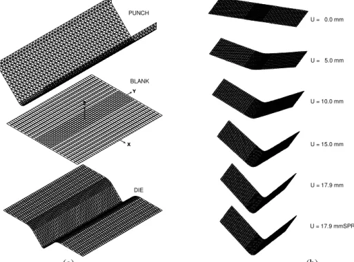
圖(四)顯示沖頭衝程達 15mm 時工件的變形 圖,從圖中可以看出由於工件受到沖頭的擠 壓,並且受到沖模在外徑方向的拘束,所以 工件將沿著沖頭與沖模之間的間隙流動,因 此工件在沖頭衝程達 15mm 時的高度將會 比原來的初始高度高,圖(五)則顯示在沖頭 衝程達 15mm 時,成形工件之數位影像擷 取。
圖(六)顯示沖頭衝程達 15mm 時工件的 有效應力分佈圖,由圖中可看出最大有效應 力值發生在工件與沖頭底部圓弧角相接觸 的部分,由於在工件此區域承受較大的壓縮 應力,因此在有最大有效應力值為 182MPa。
圖(七)顯示沖頭衝程達 15mm 時工件的 有效應變分佈圖,由圖中可看出最大有效應 力發生在工件與沖頭底部圓弧角相接觸的 部分其值為 3.31。
五、結論
本計畫採用顯性動態有限元素法,結合 有限變形理論及 ULF 的觀念,建立一增量 型彈塑性大變形的三維有限元素分析程 式,用以模擬金屬柱材擠製成形,根據分析 之結果,以套裝軟體做為後處理的圖形輸 出。此外,根據擠製成形製程,設計一組後 向擠製模具,於 500kN 油壓成形機上加以 實驗。利用此分析程式,將可在第三年之計 畫中做為探討金屬板材三維深引伸成形極 限在數值分析方面的基礎。
圖(八)顯示分析程式結合破裂模組之 流程圖,在擠製成形製程中,當胚料達到破 裂準則之臨界值時,則節點將產生分離,且 增加一新節點,此外亦記錄構成元素之節點 號碼。在第二年修正模擬結果未盡理想,需 要再深入探討。
4
參考文獻
[1] D. Liu, Z. J. Luo, M. X. Gu, The algorithm of automatic local mesh subdivision and its application to finite-element analysis of a large deformation forming process, J. Mater. Pro.
Tech., Vol. 83, p. 164-169, 1998
[2] B. Bennani and J. Oudin, Backward can extrusion of steels : effects of punch design on flow mode and void volume fraction, Int.
J. Mach. Tools Manufact., Vol. 35, No. 6., p. 903-911, 1995.
[3] Jin Hee Kim and Seung Jo Kim, A finite element analysis of damage propagation during metal forming process, Engineering Fracture Mechanics, Vol. 51, No. 6, p.
915-931, 1995
[4] Y.-M. Guo, Y. Yokouchi, K. Nakanishi, Hot backward extrusion comparative analyses by a combined finite element method, International Journal of Mechanical Sciences, Vol. 42, p.
1867-1885, 2000
[5] Ho-Joon Choi, Jin- Hwa Choi, Beong-Bok Hwang, The forming characteristics of radial- backward extrusion, J. Mater. Pro.
Tech., Vol. 113, p. 141-147, 2001
[6] Y.-M. Guo, K. Nakanishi, A backward extrusion analysis by the rigid-plastic integralless-meshless method, J. Mater. Pro.
Tech., Vol. 140, p. 19-24, 2003
[7] K. D. Hur, Y. Choi, H.T. Yeo, A design method for cold backward extrusion using FE analysis, Finite Elements in Analysis and Design, Vol. 40, p. 173-185, 2003 [8] B. Bennani, N. Bay, Limits of lubrication
in backward can extrusion: analysis by the finite-element method and physical modeling experiments, J. Mater. Pro. Tech., Vol. 61, p. 275-286, 1996
[9] Hae Yong Cho, Gyu Sik Min, Chang Yong Jo, Myung Han Kim, Process design of the cold forging of a billet by forward and backward extrusion, J. Mater. Pro.
Tech., Vol. 135, p. 375-381, 2003
[10] M. G. Cockcroft, D.J. Latham, , J. Inst.
Metals, Vol. 96, p. 33-39, 1968
圖 表
圖(一) 後向擠製之實驗設備
50.0
R3.0
50.0
Workpiece
40.0
Punch
28.0
Die
圖(二) 後向擠製模具組合圖
圖(三) 有限元素之分析模型
5
圖(四) 數值分析結果
圖(五) 成形工件之數位影像
圖(六) 工件之有效應力分佈圖
圖(七) 工件之有效應變分佈圖
圖(八) 分析程式結合破裂模組之流程圖
6
出席第七屆亞太塑性工程及其應用研討會 心得報告
報 告 人 姓 名 : 黃 佑 民
服 務 機 構 及 職 稱 : 國 立 台 灣 科 技 大 學 機 械 系 教 授
會 議 時 間 地 點 : 2 0 0 4 年 9 月 2 2 - 2 6 日 於 中 國 上 海 市 國 科 會 核 定 計 畫 編 號 : N S C 9 3 - 2 2 1 2 - E - 0 1 1 - 0 0 8
會 議 名 稱 : 第 七 屆 亞 太 塑 性 工 程 及 其 應 用 研 討 會
The 7th Asia-Pacific Symposium on Engineering Plasticity and Its Application
發 表 論 文 題 目 : 1. An Effect of Material Parameters on the Camber Behavior
2. An Influence of Tool Profiles on the V-bending Process of Sheet Metal
一 . 參 加 會 議 經 過 :
此 研 討 會 之 主 題 是 針 對 各 種 塑 性 加 工 工 程 領 域 ( 包 括 材 料 之 構 成 方 程 式 、 材 料 之 破 壞 、 實 驗 與 數 值 模 擬 技 術 、 最 新 材 料 之 塑 性 行 為 、 材 料 之 塑 性 成 形 製 程 分 析 、 超 塑 性 材 料 等 ) 的 研 究 發 表 與 心 得 交 換 , 讓 與 會 者 能 透 過 此 研 討 會 共 享 研 究 成 果 。 此 研 討 會 為 第 七 屆 , 由 National Natural Science Foundation of China 、 Shanghai Jiao Tong University 、 Chinese Society of Theoretical and Applied Mechanics 、 Shanghai Society of Mechanics 及 Hong Kong Society of Theoretical and Applied Mechanics 連 合 主 辦 , 本 人 將 近 年 來 於 金 屬 製 程 之 研 究 心 得 , 應 用 於 三 維 V 形 彎 曲 成 形 製 程 之 成 果 , 藉 由 參 加 此 次 研 討 會 , 與 世 界 各 國 之 學 者 專 家 做 一 次 面 對 面 的 溝 通 與 交 換 心 得 , 了 解 各 國 在 有 關 塑 性 加 工 方 面 之 進 展 , 做 為 日 後 研 究
- 1 -
之 參 考 。 研 討 會 分 為 十 場 Sessions發 表 , Session 1發 表 的 主 題 為 Damage and Failure, Session 2發 表 的 主 題 為 Fatigue,
Session 3發 表 的 主 題 為 Constitutive model, Session 4發 表 的 主 題 為 Multi-Scale , Session 5 發 表 的 主 題 為 Forming and Machining , Session 6 發 表 的 主 題 為 Numerical technology , Session 7發 表 的 主 題 為 Experimental technology, Session 8發 表 的 主 題 為 Rate and time dependency, Session 9發 表 的 主 題 為 Stress and Strength及 Session 10發 表 的 主 題 為 Advanced material and structure, 共 有 來 自 世 界 各 地 一 百 多 篇 論 文 發 表 。 本 人 所 發 表 之 論 文 被 安 排 在 第 三 天 第 五 Session 的 第 19、 21位 發 表 , 由 於 發 表 的 論 文 很 多 , 所 以 每 篇 論 文 之 發 表 時 間 只 有 二 十 分 鐘 , 因 此 必 須 非 常 簡 要 , 如 果 有 需 深 入 的 了 解 的 話 , 就 必 須 於 會 後 私 底 下 討 論 。 本 人 所 發 表 的 內 容 較 偏 重 於 金 屬 成 形 加 工 製 程 之 模 擬 處 理 , 因 此 引 起 許 多 學 者 專 家 之 興 趣 , 所 以 會 後 於 會 場 聚 集 一 起 討 論 , 有 些 學 者 也 提 出 他 們 的 處 理 方 式 供 我 參 考 , 因 此 獲 益 甚 多 。
二 . 與 會 心 得 :
此 次 會 議 之 特 色 在 於 邀 請 十 位 Keynote Speaker 演 講 , 在 其 演 講 時 間 排 於 第 一 天 , 以 便 大 家 都 去 聽 , 這 些 主 題 都 是 有 關 最 近 在 塑 性 工 程 領 域 之 研 究 , 由 這 些 論 文 之 發 表 , 讓 我 了 解 在 相 關 領 域 之 各 國 學 者 之 研 究 方 向 與 研 究 成 果 , 並 讓 我 深 深 體 會 我 們 該 努 力 的 地 方 還 是 相 當 多 。 此 行 除 了 讓 我 了 解 到 目 前 世 界 上 之 研 究 成 果 與 未 來 之 動 向 外 , 並 利 用 聽 講 之 機 會 與 參 加 的 各 國 人 士 交 換 意 見 並 了 解 他 們 在 做 些 什 麼 樣 的 研 究 , 增 加 一 些 研 究 上 之 經 驗 , 故 本 人 覺 得 此 行 非 常 值 得 , 對 本 人 將 來 之 研 究 助 益 相 當 大 。
- 2 -
三 . 建 議 :
此 次 經 國 科 會 補 助 , 使 筆 者 得 有 機 會 參 加 這 次 的 國 際 會 議 , 除 了 發 表 研 究 論 文 並 了 解 各 國 先 進 所 給 予 之 見 解 外 , 並 進 而 獲 悉 世 界 各 國 在 塑 性 工 程 領 域 方 面 之 新 思 維 與 將 來 研 究 之 趨 勢 , 可 謂 受 益 良 多 。 此 次 會 議 之 舉 行 , 中 國 的 上 海 交 通 大 學 挑 起 主 辦 的 責 任 , 希 望 將 來 我 們 也 能 有 一 些 機 會 能 結 合 各 校 之 力 量 , 舉 辦 一 些 這 類 型 國 際 性 的 研 討 會 , 藉 此 不 但 可 提 升 學 術 風 氣 外 , 亦 可 提 高 我 們 的 國 際 地 位 。
四 . 攜 回 資 料 名 稱 及 內 容 :
Proceeding of The 7th Asia-Pacific Symposium on Engineering Plasticity and Its Application, Part I and Part II.
- 3 -
An Influence of Tool Profiles on the V-bending Process of Sheet Metal You-Min Huang1,a and Tsung-Chia Chen2,b
1 Department of Mechanical Engineering, National Taiwan University of Science and Technology.
43 Keelung Rd., Sec. 4, Taipei 106, Taiwan.
2 Department of Mechanical Engineering, National Chin-Yi Institute of Technology.
35 Lane 215, Chung-Shan Rd., Sec. 1, Taiping City, Taichung County 411, Taiwan.
a[email protected], b[email protected]
Keywords: elastic-plastic analysis, V-bending, springback, camber profile.
Abstract. An incremental elastic-plastic finite-element computer code, based on an updated Lagrangian formulation, was developed to simulate the V-die bending of sheet metal. In particular, the degenerated shell element was used to formulate the stiffness matrix. The r-minimum method was used to treat the elastic-plastic state and solve contact problems at the tool-metal interface. A series of experiments were performed to validate the theoretical formulation, supporting the development of the computer codes. Simulation results, such as the camber height associated with bending and the bending angle of the bent part after unloading were compared with experimental data, and the results were consistent. The simulation including the springback behavior was performed to evaluate the effects of the tool profiles such as punch radius (Rp), die radius (Rd) and angle of tool (At).
Introduction
The V-die bending process is a non-steady-state process with two distinct phases - air bending and coining. The conventional method for predicting an unloading state after forming does not apply to coining, as it is generally based on pure moment bending. Consequently, the unloading state after forming during V-die bending is hard to estimate. Moreover, the camber profile along the bend axis after unloading is not clearly determined in a 2D axial symmetrical simulation. In this work, incremental elastic-plastic 3D finite element computer code clearly simulates the camber profile along the bend axis after unloading.
The V-bending of sheet metal has attracted only a little interest in the past, although the field has been extensively described [1]. Weinmann and Shippell [2] presented experimental results on the V-die bending of a hot-rolled, high-strength, low-alloy steel sheet; both the maximum air bending force and the elastic unloading state during coining were assessed as functions of punch radius, die width and the thickness of the sheet. Magnusson and Tan [3] used elementary bending theory with pure moment bending (without transverse stresses) to analyze V-die bending. Huang [4,5] performed an elastic-plastic incremental finite-element calculation to analyze the V-bending process with planar strain without friction, and to investigate spring-back and spring-forward phenomena. Ogawa et al.
[6] accurately predicted spring-back in a V-bending process without friction, using the finite-element method with element meshes of various sizes; they compared the results to experimental results.
An incremental elastic-plastic finite element computer code, based on an updated Lagrangian scheme, is adopted to simulate the V-die bending processes efficiently. The method is used to treat the shell elements associated with the finite-element model. An r-minimum method is used herein to determine the dependence of the sheet-tool contact on deformation. Experimental results concerning the V-die bending process were obtained and compared to the results of the finite-element simulation, to verify the efficiency of the finite-element computer code. This work performs experiments and simulations to investigates the effects of tool profiles on the camber height, springback angle after unloading and distribution of thickness along the bend axis.
Key Engineering Materials Vols. 274-276 (2004) pp. 553-558 online at http://www.scientific.net
© 2004 Trans Tech Publications, Switzerland
Licensed to You-Min Huang ([email protected]) - National Taiwan University of Science and Technology - Taiwan ROC
All rights reserved. No part of the contents of this paper may be reproduced or transmitted in any form or by any means without the
Basic Theory
Variational Principle. The updated Lagrangian formulation is based on the modified principle of virtual velocity [7]:
∫
∫ − + =
St
i i V
ij ik jk ij ik ik J
ij σ D δD σ L δL dV fδvdS
σ 2 ) } &
{( . (1)
where σJ is the Jaumann derivative of Cauchy stress σ . L is the gradient of the velocity field (L=∂v/∂x); D and W are, respectively, the symmetric and anti-symmetric parts of L. The derivation of this equation considers the fact that, for sheet metal forming, det(∂x/ x∂ 0)≅1. Hence,
J
J σ
τ = where τJ is the Jaumann derivative of the Kirchhoff stress. Constitutive equations can be defined as a small strain, linear elasticity and the large deformation, rate-independent, work-hardening plasticity [8]:
kl ep ijkl kl ep ijkl J
ij =C D =C L
σ . (2)
where Cijklep is the symmetric tangent constitutive matrix.
Substituting Eq. (2) into Eq. (1) yields the final form of the principle of virtual velocity:
∫
∫ =
St
i i V
ij kl
ijklL L dV f vdS
C δ &δ . (3)
where,
ijkl ep ijkl Cijkl
C = +Ω ; Ωijkl =
(
σjlδik −σikδjl −σilδjk −σjkδil)
2
1 .
Stiffness Equation. The aforementioned problem is solved in the standard way: Eq. (3) is integrated from time t to t+∆t, where ∆t is a small time increment. All rate quantities are simply replaced by incremental quantities, assuming that rates are maintained constant in each incremental step. Standard finite element discretization, and the introduction of an elemental shape function enable Eq. (3) to be replaced by a system of algebraic equations,
C F u
K∆ =∆ +∆ . (4) where K is the elastic-plastic stiffness matrix and ∆u represents the nodal displacement increment.
The terms ∆F and ∆C are taken from the right-hand side of Eq. (3). The stiffness matrix K is described at time t and is considered to be a constant within the time increment ∆t. The so-called
“r-minimum” method [9] is applied to limit the size of the time step.
Experimental Design and FEM Analysis
Experiments. Numerous experiments were undertaken to elucidate the effects of process variables and check the developed finite-element computer code. The China Steel Corporation supplied the experimental equipment and data about the material. Figure 1(a) presents the tool profile and the initial conditions. Table 1 details the dimensions of the blank and other data about the blank pertinent to the experiments. Figure 1(b) plots the camber profile, where W is the blank width; L is the blank length; As is the bend angle after unloading; δ is the camber height, and t is the distribution of thickness along bend axis. The stress-equivalent plastic strain relationship of a sheet is represented by
Advances in Engineering Plasticity and Its Applications 554
an n-power law of the form σ =c(ε0 +εp)n. The lubricant used in the experiment was a Teflon film lubricant. The experiments were simulated and the friction coefficient µ =0.01 assumed to realize satisfactory lubrication, and thereby validate the use of the developed finite-element method.
Table 1. Material constants and blank dimensions for experiments to verify the effects of tool profiles in a V-die bending process. (Units: mm)
Type Thickness (t0) Width (W) Length (L) Yield stress (MPa) Stress-plastic strain relation
M1 12.0
M2 2.0
24.0 291 σ =550.87(0.0135+εp)0.1483
M3 12.0
M4 6.0
24.0
60.0
420 σ =617.94(0.0207+εp)0.0971
Note: Young’s modulus E = 218.1 GPa, Poisson’s ratio ν= 0.3.
Contact Search and Friction. The contact algorithm must be able to deal with the following problems; (1) contact search, (2) generating the local coordinate base vectors for contacting nodes, and (3) integrating the frictional force. The approach taken to describing the surface geometry of the tool strongly affects the contact search procedure. Mesh description approaches can be taken to describing the three-dimensional surface, because the contact search procedure is efficient and simple [10].
Treating the Elastic-Plastic and Contact Problems. The contact condition between the tools and the blank at each node should remain in the same state during incremental deformation. An extended r-minimum technique was employed such that each incremented step size is determined not only by the yielding of an element Gaussian point, but also by the change in the boundary condition along the tool-sheet interface.
Unloading. Spring-back or spring-forward is significant in sheet forming; therefore, the unloading behavior following sheet forming is considered. The unloading procedure is executed, and geometrical contact with the tool is replaced by an equivalent reaction force model. That is, the tools are completely removed at the beginning of the spring-back calculation, and new force boundary conditions are prescribed at all contacted nodes, by setting ∆f =−f . Then, the calculations are repeated until all nodal forces disappear. All tools are removed during elastic unloading.
Results and Discussion
Verifying the Finite-Element Model. A four-node rectangular shell element was used to derive a stiffness matrix. The established tools and blank were meshed and transferred into a data file using CAD software (I-DEAS). Incremental elastic-plastic 3-D finite element computer code performed the numerical analysis.
Table 2. Experimental data and simulation results of springback angle and Camber height in a V-die bending process.
Springback angle (Ast: degree) Camber height (δ : mm) Material
type Experiment Simulation Error Experiment Simulation Error
M1 0.5 0.2 0.3 0.28 0.35 0.07
M2 1.8 1.2 0.6 0.25 0.30 0.05
M3 2.0 1.6 0.4 0.24 0.29 0.05
M4 2.4 2.1 0.3 0.22 0.28 0.06
Note: At = 90˚; Rp = 3.0 mm; Rd = 15.0 mm; Wp = 40.0 mm.
Table 2 presents that the calculated springback angle (Ast) after unloading in the final bending stage matches the experimental data for various types of material. The maximum tolerated error in predicting the springback angle after unloading during the final bending stage is 0.6°. Additionally, Table 2 reveals that the calculated camber height (δ ) after unloading during the final bending stage is Key Engineering Materials Vols. 274-276 555
consistent with the experimental data for various types of material. The maximum tolerated error in predicting the camber height after unloading in the final bending stage is 0.07 mm. The comparison between the experimental data and the simulated results shows minor differences between them.
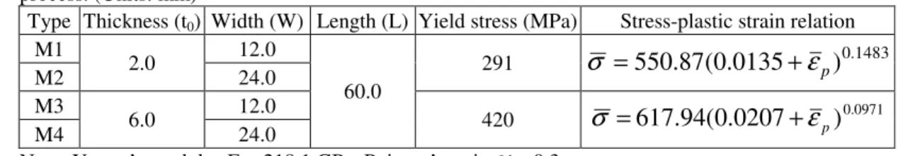
Effect of Tool Angle on a V-die Bending Process (Figs. 2-3). Figure 2(a) shows that the springback angle (Ast) increases as the tool angle decreases. When the blank is thick and wide (M4 type), the influence is obvious. Figure 2(b) indicates that the camber height (δ ) declines as the tool angle increases. When the blank is thin and narrow (M1 type), the influence is obvious but when the blank is thick (M3, M4 type), the effect of blank width on the camber height is negligible. Figure 3 shows that the thickness of the bend axis is minimized when the tool angle decreases and the blank width increases. The thickness distribution figure indicates that the thickness of the bend axis at the end of the Y-axis is minimized when the blank is thin and narrow and the tool angle decreases (M1 type;
At=30°).
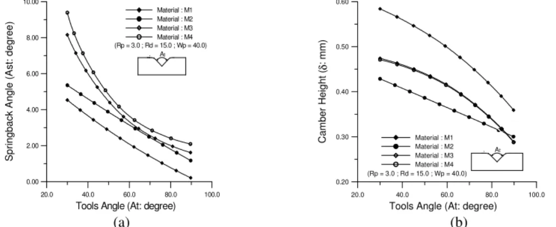
Effect of Die Radius on a V-die Bending Process (Figs. 4-5). Figure 4(a) shows that the springback angle (Ast) slightly increases when the die radius increases. When the blank is thick and wide (M4 type), this influence is obvious. Figure 4(b) indicates that the camber height (δ ) of the thin blank (M1, M2 type) is constant when the die radius varies. However, when the blank is thick (M3, M4 type), the camber height slightly increases with the die radius. Figure 5 shows that the effect of the die radius on the thickness distribution of bend axis is insignificant.
Effect of Punch Radius on a V-die Bending Process (Figs. 6-7). Figure 6(a) shows that the springback angle (Ast) increases with the punch radius. When the blank is thin (M1, M2 type), this effect is obvious. Figure 6(b) shows that the camber height (δ ) increases with the punch radius.
When the blank is thick and narrow (M3 type), this effect is obvious. Figure 7 indicates that the thickness of the middle of the Y-axis is minimized by reducing the punch radius and increasing the blank width. The thickness distribution figure indicates that the thickness of the bend axis at the end of the Y-axis is minimized when the blank is thin and narrow and the punch radius increases (M1 type; Rp=6.0, Rp=9.0).
Conclusions
Results concerning the effects of tool profiles on the camber height, the thickness distribution of the blank along the bend axis and the bend angle after unloading, as considered to obtain an accurate geometrical configuration, are summarized below: (1) The springback angle (Ast) increases when the die radius or the punch radius increases, or the tool angle decreases. (2) The camber height increases when the punch radius increases or the tool angle decreases. (3) The camber height of the thin blank (M1, M2 type) is constant as the die radius varies. However, when the blank is thick (M3, M4 type), the camber height increases slightly with the die radius. (4) The thickness of the bend axis is minimized as the tool angle decreases and the blank width increases. (5) The thickness of the middle of the Y-axis is minimized as the punch radius decreases and the blank width increases. (6) The effect of the die radius on the thickness distribution along the bend axis is insignificant. (7) The thickness of bend axis at the end of the Y-axis is minimized when the blank is thin and narrow and the tool angle is decreased or when the blank is thin and narrow and the punch radius is increased.
Acknowledgments
The authors would like to thank the National Science Council of the Republic of China for financially supporting this research under grant No. NSC 90-2212-E-011-041.
References
[1] K. Lange: Handbook of Metal Forming (McGraw-Hill, New York, 1985).
Advances in Engineering Plasticity and Its Applications 556
[2] K.J. Weinmann and R.J. Shippell: Sixth North American Metal Working Research Conference Proceeding (May 1978), p. 220
[3] C. Magnusson and Z. Tan: Proceedings of 16th Biannual IDDRG Congress (May 1990), p. 363 [4] Y.M. Huang, H. Takizawa, A. Makinouchi and T. Nakagawa: Spring Proceedings on Plastic
Working (1989), p. 275
[5] Y.M. Huang, Y.H. Lu and A. Makinouchi: J. of Mater. Proc. Tech. Vol. 35 (1992), p. 129 [6] H. Ogawa, A. Makinouchi, H. Takizawa and N. Mori: Advanced Technology of Plasticity
Proceedings of Fourth International Conference on Technology of Plasticity (1993), p. 1641 [7] R.M. McMeeking and J.R. Rice: Int. J. Solids Structures Vol. 11 (1975), p. 601
[8] H.L. Cao and C. Teodosiu: Conference proceedings: Computational Plasticity - fundamentals and applications (1989), p. 959
[9] Y. Yamada, N. Yoshimura and T. Sakurai: Int. J. of Mech. Sci. Vol. 10 (1968), p. 343 [10] Santos and A. Makinouchi: Proceedings of Numisheet'93 (1993), p. 261
PUNCH
Wp
Rp At t0
Rd Wd
L Y X
Z
Units:mm DIE
BLANK
Wp : Punch Width Wd : Die Width
Rp : Punch Radius Rd : Die Radius At : Tools Angle t0 : Blank Thickness Wp = Wd
L : Blank Length W : Blank Width
t : Bend Axis Thickness
L
As W
δ t
As : Springback Angle Ast = As - At
: Camber Height
δ
(a) (b)
Fig. 1. (a)Tools geometry and initial conditions in a V-die bending process. (b)Deformed geometries in a V-die bending process at final stage after unloading (M2 type).
Material : M1 Material : M2 Material : M3 Material : M4 (Rp = 3.0 ; Rd = 15.0 ; Wp = 40.0)
At
20.0 40.0 60.0 80.0 100.0
Tools Angle (At: degree)
0.00 2.00 4.00 6.00 8.00 10.00
SpringbackAngle(Ast:degree)
(Rp = 3.0 ; Rd = 15.0 ; Wp = 40.0) Material : M1 Material : M2 Material : M3 Material : M4
20.0 40.0 60.0 80.0 100.0
Tools Angle (At: degree)
0.20 0.30 0.40 0.50 0.60
CamberHeight(δmm):
At
(a) (b)
Fig. 2. (a) The effect of tool angle on the springback angle with varied blank width and varied blank thickness. (b) The effect of tool angle on the camber height with varied blank width and varied blank thickness.
(Rp = 3.0 ; Rd = 15.0 ; Wp = 40.0) Material: M1 ;At = 60o
Material: M1 ;At = 30o Material: M1 ;At = 90o
Material: M2 ;At = 30o Material: M2 ;At = 60o Material: M2 ;At = 90o
-15.0 -10.0 -5.0 0.0 5.0 10.0 15.0
Relative Position - Y Axis (mm)
1.80 1.85 1.90 1.95 2.00 2.05 2.10
Thickness(mm) (Rp = 3.0 ; Rd = 15.0 ; Wp = 40.0)
Material: M3 ;At = 60o Material: M3 ;At = 30o Material: M3 ;At = 90o
Material: M4 ;At = 30o Material: M4 ;At = 60o Material: M4 ;At = 90o
-15.0 -10.0 -5.0 0.0 5.0 10.0 15.0
Relative Position - Y Axis (mm)
4.25 4.50 4.75 5.00 5.25 5.50 5.75
Thickness(mm)
Fig. 3. The effect of tool angle on the thickness distribution of bend axis with varied blank width and varied blank thickness.
Key Engineering Materials Vols. 274-276 557
0.0 3.0 6.0 9.0 12.0 15.0 18.0
Die Radius (Rd: mm)
0.00 0.40 0.80 1.20 1.60 2.00 2.40
SpringbackAngle(Ast:degree)
(Rp = 3.0 ; Wp = 40.0 ; At = 90o) Material : M1 Material : M2 Material : M3 Material : M4
Rd
(Rp = 3.0 ; Wp = 40.0 ; At = 90o) Material : M1 Material : M2 Material : M3 Material : M4
0.0 3.0 6.0 9.0 12.0 15.0 18.0
Die Radius (Rd: mm)
0.20 0.24 0.28 0.32 0.36
Camber Height (δ: mm)
Rd
(a) (b)
Fig. 4. (a) The effect of die radius on the springback angle with varied blank width and varied blank thickness. (b) The effect of die radius on the camber height with varied blank width and varied blank thickness.
-15.0 -10.0 -5.0 0.0 5.0 10.0 15.0
Relative Position - Y Axis (mm)
1.84 1.88 1.92 1.96 2.00 2.04 2.08
Thickness (mm)
Material: M1 ;Rd = 9.0 Material: M1 ;Rd =15.0
Material: M1 ;Rd = 3.0 Material: M2 ;Rd = 3.0 Material: M2 ;Rd =15.0 Material: M2 ;Rd = 9.0 (Rp = 3.0 ; Wp = 40.0 ; At = 90o)
-15.0 -10.0 -5.0 0.0 5.0 10.0 15.0
Relative Position - Y Axis (mm)
4.50 4.70 4.90 5.10 5.30 5.50 5.70
Thickness (mm)
Material: M3 ;Rd = 3.0 Material: M4 ;Rd = 3.0 Material: M4 ;Rd = 9.0 Material: M4 ;Rd =15.0 Material: M3 ;Rd =15.0
Material: M3 ;Rd = 9.0
(Rp = 3.0 ; Wp = 40.0 ; At = 90o)
Fig. 5. The effect of die radius on the thickness distribution of bend axis with varied blank width and varied blank thickness.
(Rd = 15.0 ; Wp = 40.0 ; At = 90o) Material : M1 Material : M2 Material : M3 Material : M4
0.0 3.0 6.0 9.0 12.0
Punch Radius (Rp: mm)
0.00 1.00 2.00 3.00 4.00 5.00 6.00
Springback Angle (Ast: degree) Rp
(Rd = 15.0 ; Wp = 40.0 ; At = 90o) Material : M1 Material : M2 Material : M3 Material : M4
0.0 3.0 6.0 9.0 12.0
Punch Radius (Rp: mm)
0.25 0.30 0.35 0.40 0.45 0.50
Camber Height (δ: mm)
Rp
(a) (b)
Fig. 6. (a) The effect of punch radius on the springback angle with varied blank width and varied blank thickness. (b) The effect of punch radius on the camber height with varied blank width and varied blank thickness.
-15.0 -10.0 -5.0 0.0 5.0 10.0 15.0
Relative Position - Y Axis (mm)
1.84 1.88 1.92 1.96 2.00 2.04 2.08
Thickness (mm)
Material: M1 ;Rp = 6.0 Material: M1 ;Rp = 9.0
Material: M1 ;Rp = 3.0 Material: M2 ;Rp = 3.0 Material: M2 ;Rp = 9.0 Material: M2 ;Rp = 6.0 (Rd = 15.0 ; Wp = 40.0 ; At = 90o)
-15.0 -10.0 -5.0 0.0 5.0 10.0 15.0
Relative Position - Y Axis (mm)
4.50 4.70 4.90 5.10 5.30 5.50 5.70
Thickness (mm)
Material: M3 ;Rp = 6.0 Material: M3 ;Rp = 9.0
Material: M3 ;Rp = 3.0 Material: M4 ;Rp = 3.0 Material: M4 ;Rp = 9.0 Material: M4 ;Rp = 6.0 (Rd = 15.0 ; Wp = 40.0 ; At = 90o)
Fig. 7. The effect of punch radius on the thickness distribution of bend axis with varied blank width and varied blank thickness.
Advances in Engineering Plasticity and Its Applications 558
An Effect of Material Parameters on the Camber Behavior You-Min Huang1,a and Tsung-Chia Chen2,b
1,2 Department of Mechanical Engineering, National Taiwan University of Science and Technology.
43 Keelung Rd., Sec. 4, Taipei 106, Taiwan
a[email protected], b[email protected]
Keywords: metal forming, elasto-plastic, finite element, V-bending process.
Abstract. A methodology for formulating an elasto-plastic finite element model, based on the updated Lagrangian Formulation, Prandtl-Reuss flow rule, and Hill’s yield criterion is developed to analyze the process conditions of the V-die bending of sheet metal. Simulation results include the deformation diagrams in different forming stages, the phenomenon of springforward or springback and variation of the workpiece thickness were obtained. The springforward phenomenon occurs when the blank is thin and narrow and normal anisotropy increases. The camber height increases with the normal anisotropy and strain hardening exponent. The thickness of the bend axis is minimized when the blank is thin and narrow, strain hardening exponent and normal anisotropy decreases.
Introduction
Although the bending sheet-metal is simple, the bending operation presents many technical problems during manufacture. These include the need to predict springback or springforward after forming;
determining the accuracy of the component shape; tackling the origination of fractures from the stretched surface, and estimating the punch load of the V-die bending when the press is selected.
Moreover, the camber profile along the bend axis after unloading is not clearly determined in a 2D axial symmetrical simulation. In this work, the incremental elastic-plastic 3D finite element computer code clearly simulates the camber profile along the bend axis after unloading.
In an effort to better understand sheet forming processes, various research works have been carried out using diverse technologies involving analytical and computational methods. Among them, the computational method, especially the finite element method (FEM), has made significant progress during the last two decades, partly because of the rapid development of computer capabilities.
Weinmann and Shippell [1] presented experimental results on the V-die bending of a hot-rolled, high-strength, low-alloy steel sheet; both the maximum air bending force and the elastic unloading state during coining were assessed as functions of punch radius, die width and the thickness of the sheet. Magnusson and Tan [2] used elementary bending theory with pure moment bending (without transverse stresses) to analyze V-die bending. Huang [3,4] performed an elastic-plastic incremental finite-element calculation to analyze the V-bending process with planar strain without friction.
Ogawa et al. [5] accurately predicted spring-back in a V-bending process without friction, using the finite-element method with element meshes of various sizes. The extended r-minimum method [6]
has been proposed to solve the contact problem during draw-bending. This scheme successfully handled the conditions at the interface between the sheet and the tool.
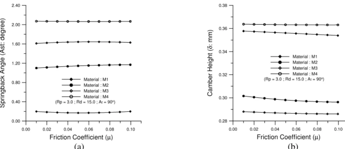
An incremental elastic-plastic finite element computer code, based on an updated Lagrangian scheme, is adopted to simulate the V-die bending camber processes efficiently. A special feature of the scheme is the assumed strain field (ASF) element [7], which has been proven to be efficiently applicable to nearly incompressible material. The method is used to treat the shell elements associated with the finite-element model. An r-minimum method is used herein to determine the dependence of the sheet-tool contact on deformation. Using the finite-element code, simulations were run to evaluate the effects of strain hardening exponent (n), friction coefficient (µ ) and normal anisotropy (R) on the camber height, springback angle after unloading and the distribution of thickness along the bend axis.
Key Engineering Materials Vols. 274-276 (2004) pp. 565-570 online at http://www.scientific.net
© 2004 Trans Tech Publications, Switzerland
Licensed to You-Min Huang ([email protected]) - National Taiwan University of Science and Technology - Taiwan ROC
All rights reserved. No part of the contents of this paper may be reproduced or transmitted in any form or by any means without the