Manipulating the generation of Ca-alginate microspheres using microfluidic
channels as a carrier of gold nanoparticles
Keng-Shiang Huang, Tzung-Heng Lai and Yu-Cheng Lin*
Received 5th May 2006, Accepted 8th May 2006First published as an Advance Article on the web 18th May 2006 DOI: 10.1039/b606424h
In this paper the manipulation of Ca-alginate microspheres, using a microfluidic chip, for the encapsulation of gold nanoparticles is presented. Our strategy is based on hydrodynamic-focusing on the forming of a series of self-assembling sphere structures, the so-called water-in-oil (w/o) emulsions, in the cross-junction microchannel. These fine emulsions, consisting of aqueous Na-alginates, are then dripped into a solution of 20% calcium salt to accomplish Ca-alginate microspheres in an efficient manner. Experimental data show that microspheres with diameters ranging from 50 mm to 2000 mm with a variation less than 5% were precisely generated. The size and gap of the droplets are tunable by adjusting the relative sheath/sample flow rate ratio. Furthermore, we applied them to encapsulated gold nanoparticles, and this one shot operation performs the ‘Lab on a Chip’.
1. Introduction
Ca-alginate beads represent one of the most widely used carriers for the immobilization of enzymes and proteins as well as for the controlled release of drugs.1–3Of critical importance to the successful implementation of Ca-alginate beads in vivo for applications such as targeted drug delivery and DNA transfection is the ability to control the particle size and size distribution, as size and its distribution influences the clearance rate from the body and ultimately determines the drug dosage.4,5The development of a narrow size distribution and reproducible method for generating Ca-alginate micro-spheres in a controlled manner is emerging.
To date, the production of alginate gel spheres has been accomplished mainly by using external gelation; alginate is extruded dropwise through a needle into a solution of divalent cations, which induces cross-linking of the guluronic residues of the alginate polymer.5The material to be encapsulated is
usually mixed with an alginate solution, and the mixture is dripped into a solution containing calcium ions, resulting in the instantaneous formation of spheres that entrap cells or drugs within a 3D-lattice. The major challenge for the conventional dripping method is that the larger beads produced (ca. millimetre scale in diameter) are not suitable for pharmaceutical applications.
The alternative techniques are (i) atomization (spray-drying),2 (ii) coacervation3 and (iii) emulsification (internal/ external gelation) methods6,7which allow the encapsulation of
a bioactive substance in small beads (ca. micrometre scale in diameter). However, the resulting size of the microspheres cannot be easily controlled by these methods, and the obtained beads tend to coagulate into large masses before hardening properly. Many researchers have attempted to make smaller particles, but less attention has been paid to obtaining
monodisperse particles. Recently, Nakajima et al. developed a novel microfluidic device that utilized a silicon micro-nozzle array to produce 50–200 mm Ca-alginate beads with a variation within 15%.8
We demonstrate in this study a microfluidic device that utilizes a cross-junction microchannel to produce 50–2000 mm Ca-alginate beads with a narrow size distribution (,5%). We chose the microfluidic chip because it has rarely been applied in controlling the generation of uniform Ca-alginate micro-spheres, and it has shown its potential in related domains.9–11 The aim of this study is to investigate and compare the size of the Ca-alginate microspheres obtained by a different ratio of flow rate in the side inlet channels to that in the center inlet channel. The developed microfluidic chip is easy to fabricate and set-up, and is easily programmed to generate a large set of ordered Ca-alginate microspheres.
2. Experimental
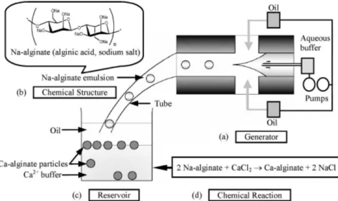
2.1. PrincipleIn this study we report the use of microfluidics to elicit control over the spontaneous self-assembly of water-in-oil (w/o) emulsions from a solution of dissolved Na-alginates (Fig. 1a). The mixture is then dripped into a solution containing calcium ions, resulting in the instantaneous formation of Ca-alginate microspheres (Fig. 1b). Our strategy is based on a focusing force to form a narrow size distribution of self-assembling sphere structures, the so-called Na-alginate emulsions. When Na-alginate emulsions were transported to the calcium chloride solution through a Teflon tube, they precipitated spontaneously at the bottom of the oil due to their higher density than that of the oil. Therefore, Na-alginate emulsions could react with calcium(II) ion at the interface between the oil phase and the water phase. Na-alginate emulsions after they have undergone cross-linking (Fig. 1c), result in Ca-alginate particle generation. The mechanism of this type of microfluidic chip in droplet-volume control has been studied recently.10–12 Department of Engineering Science, National Cheng Kung University, 1
University Road, 701 Tainan, Taiwan. E-mail: [email protected]; Fax: 886-6-276-2329; Tel: 886-6-276-2395
TECHNICAL NOTE www.rsc.org/loc | Lab on a Chip
By varying the ratio between oil and water flow rates provides finer control of the droplet sizes. Based on the outstanding performance of the microfluidic technique, we utilize it in this work for pharmaceutics (e.g. Ca-alginate particle generation). 2.2. Fabrication of a microfluidic chip
The developed microfluidic chip is laid out on a conventional poly methyl methacrylate (PMMA) substrate (length/width/ depth: 270 mm/210 mm/1.5 mm) with a laser micromachining process using a CO2 laser machine (LaserPro Venus, GCC,
Taiwan). The microfluidic chip (length/width/depth: 110 mm/ 45 mm/6 mm) consists of four layers (an expanded view is shown in Fig. 2a) are, from top to bottom: the cover layer (semi-product outlet channel), the reagent inlet layer, the main layer (cross-junction channel) and the bottom layer, respec-tively. These four layers are integrated by screws (tightened at 1y1.2 N m), followed by thermal binding in an oven (OPO-45, CHENG SANG, Taiwan) at 110 ¡ 5 uC for 90 min. This device is then naturally annealed to room temperature to produce the microfluidic chip. This platform is low cost, easy to fabricate and set up, as well as easy to organize and program. This microfluidic chip has three inlet ports, one cross-channel, an observation chamber and one outlet, as shown in Fig. 2b. The broadened channels (600 mm in width)
near the outlet of the cross channel and observation chamber (1 mm in width) are designed for slowing down the flow and enhance the analysis observation.
2.3. Experimental procedure
The procedure is as follows. First, the fluids of the center and side channels are set up with Na-alginate solution (sample flow) and oil (sheath flow), respectively. Generally speaking, the material to be encapsulated is mixed with an alginate solution. Second, the fluids are injected into the microfluidic chip by syringe pumps (Kdscientific KDS230) programmed by a PC. In this work we hydrodynamically focus a stream of aqueous tincture (Na-alginate solution, water phase) at a cross-junction microchannel by two oil streams (continuous phase), enabling the construction of w/o Na-alginate emulsions along the microchannel axis. Finally, the Na-alginate emul-sions then undergo gelation by dripping them into a calcium(II) ion solution to produce ordered Ca-alginate microspheres.
2.4. Microspheres size measurement
A fluorescence microscope is used to observe the experimental results. The image and detection system consist of an optical microscope (BX60, Olympus, Japan) and a digital camera (DP70, Olympus, Japan). The diameter of each microsphere was measured and averaged. A total of 50 microspheres were measured to provide an average size.
3. Results and discussion
3.1. Regular Na-alginate emulsionsFor the w/o Na-alginate emulsions generation, the pregel solution (which is prepared by mixing 25 mL of 13 nm gold nanoparticles13 and 5 mL of 3% (w/v) Na-alginate) and sunflower seed oil (Uni-President Enterprises Corp., Taiwan) are employed as the water-phase fluid and oil-phase fluid, respectively. A water-soluble dye (red ink) is dissolved in the pregel solution for immediate (real-time) observation. This viscous solution is then fluidified by shear forces in the microfluidic chip equipped with a cross-junction channel. Utilizing an inverted fluorescent microscope, the forming of the regular emulsions in the compartment was observed and characterized.
Fig. 1 Scheme and illustration of system set up and mechanism: (a) schematic drawing of Na-alginate emulsion generator in a cross-junction microchannel, (b) chemical structure of Na-alginate emulsion, (c) a reservoir and (d) the mechanism of Na-alginate polymerization: the chemical reaction in the reservoir is that the sodium ions of alginate are substituted by calcium ions, indicating the formation of Ca-alginate particles.
Fig. 2 Schematic drawings of a microfluidic chip: (a) expanded view, and (b) photo image: (1) oil inlet, (2) water inlet, (3) cross-junction channel, (4) observation chamber, (5) outlet, (6) screw holes for binding.
In the initial experiments, the flow rates of the liquid-phase and the oil-liquid-phase fluids were set to 0.08 mL min21and 0.8 mL min21, respectively. We found that the liquid-phase fluid (red color) was compressed by a shear force to an arrow shape (Fig. 3) and then separated into emulsions of about 200 mm in diameter. In addition, the diameter distribution of the emulsions formed is quite uniform (200 ¡ 5 mm), and the gap between each emulsion is stable (400 ¡ 10 mm). The flow rates of the oil and the pregel solution were adjusted to control the degree of hydrodynamic focusing and the width of the center stream, resulting in the generation of regular Na-alginate emulsions.
3.2. Formation of Ca-alginate microspheres
The semi-products (Na-alginate emulsions) were formed in the continuous oil flow. The continuous oil flow could prevent these semi-products from fusing together, and could transport these monodisperse emulsions to the calcium ion pool (20% (w/v) calcium chloride). After gelation for 20 min, the uniform and water-insoluble Ca-alginate microspheres were formed and observed.
The Ca-alginate microspheres were separated from the calcium chloride solution and oil by vacuum filtration. They were washed twice with 30 mL n-hexane/ether, and then cleaned with 10 mL 50 mM Tris–HCl buffer (pH 7.2). All the Ca-alginate microspheres prepared as described above were subject to freeze-drying. After being dipped in liquid nitrogen, they were dried at 270uC under vacuum (0.1 mmHg) for 10 h and then vacuum-dried at room temperature for 1 h. We found the shapes of most Ca-alginate microspheres remained spheroid after the gelation and the freeze-drying process. 3.3. Encapsulation and analysis
Simply by mixing well the water-soluble drugs with the Na-alginate solution, an excellent level of entrapment efficiency can be observed. We first examined the encapsulation of a model drug, i.e. gold nanoparticles, to verify the applicability of this microfluidic technique. Then a well mixed mixture followed the general experimental procedure (as mentioned above) to obtain gold nanoparticle-loaded Ca-alginate micro-spheres. The entrapment efficiency of gold nanoparticles was determined by a UV spectrophotometer (HP 8453, Agilent, Germany).
We found that neat 3% Na-alginates were non-absorbant in UV-Vis, but after being mixed with 13 nm gold solution (13 nm gold solution/3% Na-alginates in 5:1) an absorbance with a peak of around 520 nm was observed (The colloidal gold was
characterized by an absorption maximum at 520 nm). Furthermore, the absorption spectra of Ca-alginate beads (containing gold nanoparticles) showed a broad peak around Fig. 3 Mono-dispersed Na-alginate microemulsions are generated at the cross-junction with oil inlet: 0.8 mL min21 and water inlet: 0.08 mL min21. (The arrow indicates the direction of emulsion generation, scale bar 200 mm).
Fig. 4 UV-Vis spectrum of gold nanoparticles mixed with Na-alginate (no. 1), gold nanoparticle-loaded Ca-Na-alginate (no. 2), gold nanoparticles (no. 3) and Na-alginate (no. 4).
Fig. 5 Relationships between emulsion size and flow rates: (a) fixed water flow rate, and (b) fixed oil flow rate.
520 nm. This means that 13 nm colloidal gold was entrapped in the Ca-alginate microspheres, as shown in Fig. 4. It is of interest to note that the absorption intensity results before and after gelation were similar. We presume that there is virtually no loss during the encapsulation process.
3.4. Influence of flow rate
To gain further understanding, the relationship between size and flow speed were studied. The emulsion size is easily varied by changing the flow conditions in the microchannels. Fig. 5 shows the relationship between the flow speed (average velocity) of the phases and the emulsion size (diameter). For a given 0.8 mL min21of the continuous phase (oil flow), the emulsion size increased as the average velocity of the dispersed phase flow (aqueous flow) increased. When the oil flow was set to 1.0 mL min21, the same tendency showed, a lower dispersed phase flow resulting in a smaller droplet was observed (Fig. 5a). On the other hand, for a given 0.05 mL min21 of dispersed phase flow, the emulsion size decreases as the average velocity of the continuous phase increased. The same tendency was observed in the 0.1 mL min21of dispersed phase flow (Fig. 5b). In addition, the emulsions will not be generated when the flow speed ratio of the aqueous buffer/oil is above 1 : 1 or below 1 : 10.
The results shown in Fig. 6 were Na-alginate emulsions with a narrow distribution of size (less than 5.0 mm) and uni-gap in the microchannel, demonstrating that fine and precise control can be obtained by using microfluidic interfaces to manipulate the assembly of microparticles. Figs. 6(a) and (b) show that increasing both oil and water flow rates (the flow rate ratio of water to oil is still 1 : 10) can result in smaller emulsions being obtained. Figs. 6(c) and (d) show that when the rate of the oil flow increases, the gap distance of the emulsions increases (at the same water flow rate). It is evident that the size and gap of
the emulsions, generated in the cross-junction, are controllable and reproducible using the microfluidic technique.
4. Conclusions
The developed microfluidic chip is capable of generating relatively uniform micro-droplets and has the advantages of active control of droplet diameter, simple and low cost process, and high throughput. The approach in manipulation of Ca-alginate microspheres will provide many potential uses for pharmaceutical applications.
References
1 M. Leonarda, M. R. D. Boissesona, P. Huberta, F. Dalenconb and E. Dellacheriea, J. Controlled Release, 2004, 98, 395–405. 2 G. Coppi, V. Iannuccelli, M. T. Bernabei and R. Cameroni, Int. J.
Pharm., 2002, 242, 263–266.
3 S. C. Chen, Y. C. Wu, F. L. Mi, Y. H. Lin, L. C. Yu and H. W. Sung, J. Controlled Release, 2004, 96, 285–300.
4 A. Kikuchi and T. Okano, Adv. Drug Delivery Rev., 2002, 54, 53–77.
5 W. R. Gombotz and S. F. Wee, Adv. Drug Delivery Rev., 1998, 31, 267–285.
6 L. W. Chan, H. Y. Lee and P. W. S. Heng, Int. J. Pharm., 2002, 242, 259–262.
7 J. O. You, S. B. Park, H. Y. Park, S. Haam, C. H. Chung and W. S. Kim, J. Microencapsulation, 2001, 18, 521–532.
8 S. Sugiura, T. Oda, Y. Izumida, Y. Aoyagi, M. Satake, A. Ochiai, N. Ohkohchi and M. Nakajima, Biomaterials, 2005, 26, 3327–3331.
9 A. Jahn, W. N. Vreeland, M. Gaitan and L. E. Locascio, J. Am. Chem. Soc., 2004, 126, 2674–2675.
10 Y. C. Tan, J. S. Fisher, A. I. Lee, V. Cristini and A. P. Lee, Lab Chip, 2004, 4, 292–298.
11 V. Cristini and Y. C. Tan, Lab Chip, 2004, 4, 257–264.
12 Y. C. Tan, V. Cristini and A. P. Lee, Sens. Actuators, B, 2006, 114, 350–356.
13 K. C. Grabar, R. G. Freeman, M. B. Hommer and M. J. Natan, Anal. Chem., 1995, 67, 735–743.
Fig. 6 Emulsion formation under (a) oil inlet 0.5 mL min21, water inlet 0.05 mL min21; (b) oil inlet 0.9 mL min21, water inlet 0.09 mL min21. Under water inlet 0.03 mL min21, and (c) oil inlet 1.2 mL min21, (d) oil inlet 0.8 mL min21(scale bar 200 mm).