行政院國家科學委員會專題研究計畫 期末報告
角落板柱接頭穿透剪力強度及其變形能力
計 畫 類 別 : 個別型
計 畫 編 號 : NSC 100-2218-E-011-012-
執 行 期 間 : 100 年 08 月 01 日至 101 年 10 月 31 日 執 行 單 位 : 國立臺灣科技大學營建工程系
計 畫 主 持 人 : 鄭敏元
計畫參與人員: 碩士級-專任助理人員:Marnie B.G
報 告 附 件 : 出席國際會議研究心得報告及發表論文
公 開 資 訊 : 本計畫可公開查詢
中 華 民 國 101 年 10 月 09 日
中 文 摘 要 : 這次研究主要目的在檢核目前美國混凝土學會的設計公式在 角落板柱接頭的適用性,實驗測試了兩組大約實尺寸的角落 板柱接頭試體,主要測試變數是重力剪力係數,就是施加重 力佔規範強度的比例值,實驗結果建議目前的設計公式作以 下的修改:(1)最大剪力強度應降低為 2.0 倍混凝土強度根號 值,以及(2)重力施加在角落板柱接頭不可以超過 1.5 倍的混 凝土強度根號值。
中文關鍵詞: 板柱接頭, 角落板柱接頭, 穿透剪力, 變形能力
英 文 摘 要 : In this research, design criteria of corner slab- column connection in current ACI Building Code (ACI 318 Committee, 2011) are examined. Two approximately full-scaled corner slab-column subassemblages were tested under combined gravity load and lateral displacement reversals. Test parameter between two specimens is the gravity shear ratio, defined as the gravity load divided by the code-specified punching shear capacity. Experimental results suggest that modifications of design criteria are needed for corner slab-column connection as follows: (1) Punching shear capacity of 2.0 square root of specified concrete strength is recommended and (2) Gravity shear shall be limited to 1.5 square root of specified concrete strength.
英文關鍵詞: Slab-Column Connection, Corner Slab-Column
Connection, Punching Shear, Deformation Capacity
1 1. Introduction:
Because of its relative low construction cost, slab-column framed system is very popular in current practice. However, the building code (ACI 318 Committee, 2011) explicitly prohibits the use of slab-column frames as part of lateral-support system in high seismic region due to its low lateral stiffness and potential punching shear failure. As a result, slab-column frames are generally served as gravity-support systems in high seismic regions and stiffer members such as shear wall or moment resisting frames shall be incorporated to resist seismic loadings.
For this purpose, capability of sustaining designed gravity load when subjected to induced lateral displacement becomes a critical design issue for slab-column framed systems.
Post-earthquake evidences showed that slab-column framed systems are susceptible to punching shear failure at the connection. Several researchers proved that gravity level has significant impact on the deformation capacities (Pan and Moehle, 1989; Robertson and Durrani, 1991 and 1992). A bilinear relationship between gravity load level and deformation capacity is given in the ACI Building Code (ACI 318 Committee, 2011), as shown in Fig. 1.1.
It indicates that deformation capacity of the connection decreases as the level of gravity load increases. First presented in 2005 ACI Building Code (ACI 318 Committee, 2005), this curve is proposed by ACI 318 Committee based on several test results. However, most of those test results are interior slab-column connections. Another issue may be found when performing shear demand calculation at the corner connection (Ghali, 1989). Different approaches are adopted by different commercial software such as ADAPT-Builder (ADAPT Corporation, 2005) and Decon-STDesign (Decon Inc., 2009).
In this research, design criteria of corner slab-column connection in current ACI Building Code (ACI 318 Committee, 2011) are examined. Two approximately full-scaled corner slab- column subassemblages were tested under combined gravity load and lateral displacement reversals. Test parameter between two specimens is the gravity shear ratio, defined as the gravity load divided by the code-specified punching shear capacity. Experimental results suggest that modifications of design criteria are needed.
2. Research Objectives:
This research is aimed to review the validity of punching shear design criteria on corner slab- column connections. Two approximately full-scaled corner slab-column subassemblages are tested.
3. Literature Review:
The current ACI Building Code (ACI Committee 318, 2011) provides two alternative design procedures for slab-column connections not designed as part of lateral-force-resisting systems for structures under seismic design categories D, E and F ( ASCE/SEI 7, 2010). Throughout this report, the first design procedure is referred as “strength check procedure” and the second is referred as “deformation check procedure.”
3.1 Strength Check Procedure
In “strength check procedure,” connection shear demand Vu evaluated at the critical section, a perimeter located at d 2 distance away from the column face as shown in Fig. 3.1, should not exceed the connection shear capacityφVc; otherwise, shear reinforcement should be
2
provided. Strength reduction factor
φ
is taken as 0.75 and Vcis determined using the smallest value of Eq. (3-1) to Eq. (3-3), (units: pound and inch).d b f
Vc =4 c, o (Eq. 3-1)
d b f
Vc 4 c, o
2 ⎟⎟⎠
⎜⎜ ⎞
⎝
⎛ +
= β (Eq. 3-2)
d b b f
V d c o
o c
2 ,
20 ⎟⎟
⎠
⎜⎜ ⎞
⎝
⎛ +
= (Eq. 3-3)
Eq. (3-1) is proposed by the Joint ACI-ASCE Committee 326 (1962) which was developed mainly from the research work of Moe (1961). This expression was first adopted in the 1963 ACI Building Code (ACI Committee 318, 1963) and remained unchanged since then.
Eq. (3-2) accounts the effect of column rectangularity. Based from the test results from nine concentrically loaded interior columns, Hawkins et al. (1971) proposed an equation in determining the punching shear capacity of slab-column connections considering the effect of column rectangularity. With small modifications, the 1977 ACI Building Code (ACI Committee 318, 1977) introduced Eq. (3-2) as an additional criterion in determining the punching shear capacity of slab-column connections without shear reinforcement, where
β
isthe ratio of the long side to short side of the supporting column.
Research evidences for the development of Eq. (3-3), on the other hand, are relatively limited.
It is meant to modify punching shear capacity for connections with longer critical perimeter bo. Examples for this application include connections with drop panels, shear capitals or large columns. It has been found out (Dilger, 1989) that Eq. (3-3) is not conservative, however, ACI Building Code still adopts this equation since 1989 (ACI Committee 318, 1989).
In current ACI Building Code (2011), eccentric shear stress model presented in Eq. (3-4) is used to determine the punching shear demand Vu of the connection. This model was originally developed by Di Stasio and Van Buren (1960) and has been revised several times later (Joint ACI-ASCE Committee 326, 1962; Hanson and Hanson, 1968 ) in order to evaluate shear stress demands from both gravity load and unbalanced moments at the connection. Shear stress induced by unbalanced moment Mub is assumed to vary linearly from the centroid of the critical section, as shown in Fig. 3.2.
J c V M V
c ub v g u
±γ
= (Eq. 3-4)
In Eq. (3-4), V , is the factored gravity shear considering all possible load combinations. g Mub is the unbalanced moment transferring in the connection. While c is the distance between the point of interest where shear demand is calculated and the centroid of critical section. The Jc term in Eq. (3-4) is an ill-defined parameter to simulate polar moment of inertia. The determination of Jc value is still controversial. Detailed description can be found elsewhere (Ghali, 1989).
3
The γv term is an empirical expression used to determine the fraction of moment transferred by eccentricity of shear. Joint ACI-ASCE Committee 326 (1962) originally suggested a constant value of 0.2 which was developed based on statistical analysis from the test results of 24 interior and one edge slab-column connections. In 1968, Hanson and Hanson (1968) evaluated the test results of slab-column connections including the results from Moe (1961) and proposed a new γvvalue of 0.4. From these test results, only one exterior connection was included; the same edge connection referred in ACI-ASCE Committee 326 (1962). Instead of using a fix value, 1971 ACI Building Code (ACI Committee 318, 1971) provided a practical equation in determining γvin order to consider the column rectangularity and has remained unchanged since then. The expression for γvis defined as
2 1
3 1 2 1 1
b
v b
+
− γ =
(Eq. 3-5)
where b1and b2 are the dimensions of the critical section parallel and transverse to the direction of moment transfer, respectively, as shown in Fig. 3-1.
3.2 Deformation Check Procedure
In the “deformation check procedure,” Eq. (3-4) shall be evaluated at the “gravity-load-only,”
a condition similar to the first step of the “strength check procedure.” Again, it is necessary to have punching shear demand Vu not exceed the punching shear capacity of the connection
Vc
φ ; otherwise shear reinforcement must be designed.
Once the “gravity-load-only” requirements were met, design story drift shall be checked with the maximum allowable value which is related to the magnitude of Vug φVc as specified in Section 21.13.6(b) of the current ACI Building Code (ACI Committee 318, 2011). This provision is illustrated by a bilinear graph in Fig. 1.1. Minimum shear reinforcement should be provided if the value corresponding to design drift ratio and Vug φVc falls above the bilinear curve of Fig 1.1. The amount of shear reinforcement in the final design is to be decided from the larger requirement between “gravity-load-only” and “design displacement”
conditions.
3.3 Ductility Requirements
Connection ductility is the key concept learned from the experiences of previous earthquakes (Robertson and Johnson, 2006) in which slab-column connections designed for gravity-load- only failed in a brittle manner during lateral deformations. The concept of ductility was roughly introduced in the 1971 ACI Building Code (ACI Committee 318, 1971).
Based from the test result of four interior slab-column connections, Pan and Moehle (1989) concluded that the lateral displacement capacity and ductility of slab-column connections are highly dependent on the gravity shear ratio. Pan and Moehle (1989) suggested a gravity shear ratio of 0.4 to ensure that the connection can sustain the minimum drift capacity of 1.5 percent. Under severe seismic loading, a 1.5 percent drift is thought to be a reasonable upper bound (Pan and Moehle, 1988; Sozen, 1980) for reinforced concrete structures. Luo and Durrani (1995) suggested a drift-based punching shear failure model based on regression analysis and was later revised by Hueste and Wight (1999). The bilinear model shown in Fig.
4
1.1 was introduced in the 2005 ACI Building Code (ACI Committee 318, 2005) and remained unchanged since then.
Most of the proposed models mentioned above were developed based on the test results of interior slab-column connections. Robertson and Durrani (1991, 1992) proposed different limiting gravity shear ratios of 0.35 and 0.5 for interior and edge connections, respectively, to ensure a minimum connection drift capacity of 1.5 percent. Based on previous test results in slab-column connections, Megally and Ghali (2000) found similar results.
4. Research Methodology
To achieve the research objective, a test program was implemented. Two approximately full- scaled corner slab-column subasseblages were tested in this research.
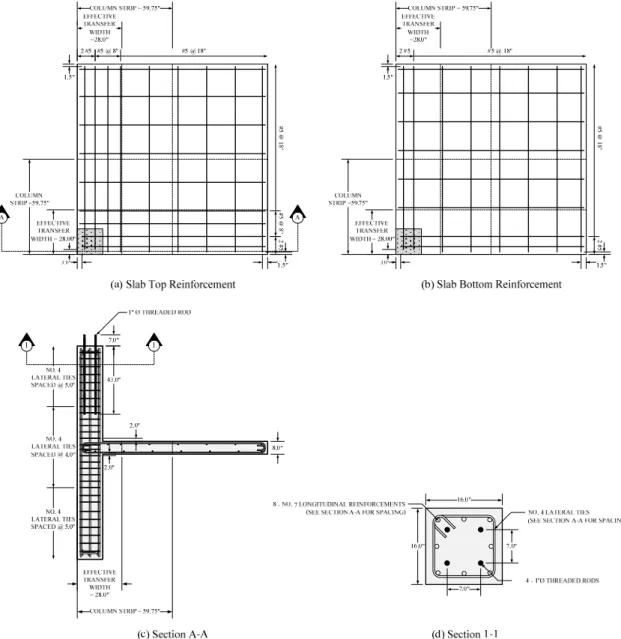
4.1.Specimen Design
Specimens are designed based on analytical results from Adapt Builder (ADAPT-FLOOR RC Ex. 3.20.1, 2008). The prototype structure has a square layout plan with 5 bays in both principal directions. Each bay has a center to center distance of 17.25 ft. Column size is 16 in.
square and slab thickness is 8 in. Gravity load is applied such that punching shear demand,V , g is 45 percent of the punching shear capacity at corner slab-column connection using a specified concrete compressive strength, f , of 5000 psi. The unbalanced moment of 31.50 c' kips-ft were then obtained in both principal directions. Flexural reinforcement is designed based on these analytical values. Test specimen final reinforcement layout is presented in Fig.
4.1.
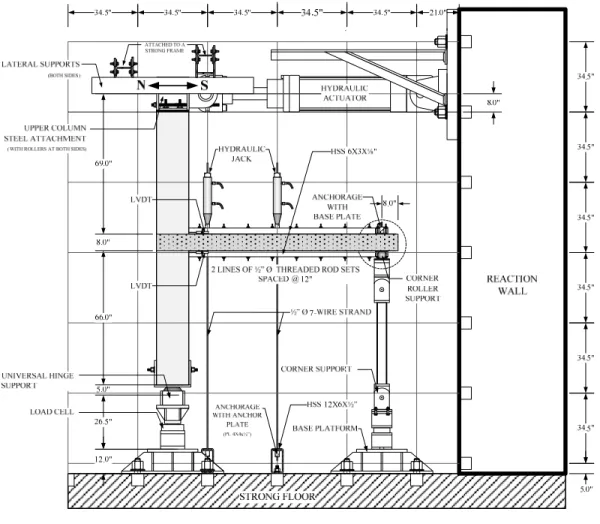
4.2.Experimental Setup
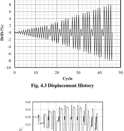
Both specimens were supported with a universal hinge at the bottom of the column and another three roller supports at the corners of the slab as shown in Fig. 4.2. Lateral support in a form of a guided roller was installed at the top of the column. A load cell was placed at the bottom of the column to monitor the gravity load variation throughout the test. Hydraulic actuator was attached at the top of the column to simulate lateral force and displacement using the loading protocol shown in Fig. 4.3.
Four linear variable differential transducers (LVDTs) – two at each principal direction placed 1 in. above and below the slab face and 6.63 in. (d) distance away from the column face – were used in each specimen to monitor the rotation of the slab relative to the column. Several strain gauges were also installed at desired locations of the flexural reinforcements to observe the extent of yielding in the reinforcement around the vicinity of the slab-column connection.
Designated gravity load was applied to the slab using 3 hydraulic jacks as shown in Fig. 4.2.
This gravity load is aimed at 30% and 50% of connection punching shear capacity for Specimen G1 and Specimen G2, respectively and adjusted after completion of each drift cycles when necessary. In Fig. 4.4, solid lines represent the adjustments of gravity load.
5. Experimental Result
5.1 General Specimen Response
5
Specimen G1 shows a good performance under cyclic loading condition as presented in its lateral load versus drift relationship in Fig. 5.1. The peak lateral load reached to about 6.9 kips (30.7 kN) at 1.75 percent drift and dropped by about 30 percent at 3.00 percent drift.
During the application of the desired gravity load, flexure cracks started to appear at the bottom of the slab. Signs of torsional stresses started to appear at 0.25 percent drift and became more obvious at higher drifts. Wider inclined cracks are already visible at the side of the slab at 2.00 percent drift and no significant crack propagation thereafter. Concrete cover spalled off at 2.50 percent drift.
Specimen G2 on the other hand failed suddenly before imposing lateral displacement. It failed due to punching shear. Closer investigation of the specimen showed that the slab was fully disintegrated from the column. Bottom longitudinal reinforcements performed well in preventing progressive collapse in specimen G2.
5.2 Shear Stress Discussion
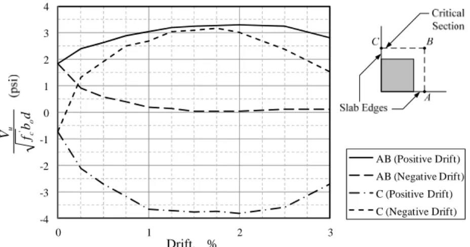
Specimen G1 performed a very ductile behavior as presented in Fig. 5.2. It reached an ultimate punching shear of about 3.8 fc'bodat 2.00 percent drift as shown in Fig. 5.2;
slightly lower than the code-specified-punching shear capacity. Theoretical analysis shows that point C of the critical section suffered the highest shear stress. The gravity shear ratio versus drift relationship of Specimen G1 shown in Fig. 5.3 provides a value above the bilinear curve implying a satisfactory deformation capacity as per ACI Building Code provisions.
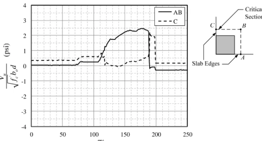
Specimen G2 which was subjected to a higher gravity loading failed in a very brittle manner.
Its peak ultimate punching shear only reached to about2.5 fc'bod and sudden loss of strength occurred thereafter as shown in Fig. 5.4.
Based from the gravity load versus drift relationships of Specimens G1 and G2 presented in Fig. 5.3, it shows that the corresponding allowable gravity shear V to sustain a 1.5 percent g drift falls slightly lower than the code-specified value.
6. Conclusions
Two identical full-scale isolated corner slab-column subassemblages were tested under cyclic lateral loading with different magnitudes of gravity shear applied on the slab. Based from the experimental results of both specimens, the following conclusions were drawn:
1. The magnitude of gravity shear essentially degrades the deformation capacity of the connection.
2. The punching shear capacity specified in current ACI Building Code may be unconservative when applied to corner slab-column connections. Based on limited test results, a 2 f (psi) shear stress capacity is suggested. c'
3. The validity of applying code-specified bilinear interaction curve between gravity shear ratio and lateral drift on corner slab-column connections requires further review.
Based from the experimental results, an upper bound of 1.5 fc' (psi) gravity shear is suggested for corner slab-column connections to ensure minimum deformation capacity.
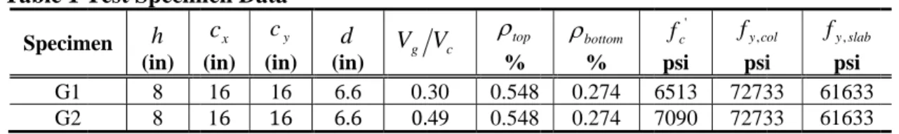
Table 1 T
Specim
G1 G2
Note: ρ
Fig. 1.1 G
Test Specim
men h (in)
8 8
h b Astop ETW
top= ,
ρ a
Gravity She
Fig. 3.2 S
men Data cx
(in) cy
(in) 16 16 16 16
and ρbottom=As,bottom
ear Ratio vs
Fig.
Stress Distri
0.00 0.01 0.02 0.03
0
Design Story Drift Ratio
d (in) g
V 6.6 0.
6.6 0.
h bETW
m ; where b
s. Drift Rati
. 3.1 Critica
bution of In
0.1 0.2 0
Shea r Reinforcem Not Required
6
Vc ρtop
% 30 0.548 49 0.548
tra effective
ETW= b
io Interactio
al Section Pe
nterior Con
0.3 0.4 0.5
Vug /φVc Shea r
ment
bottom
ρ
% 0.274 0.274
width
ansfer .
on Diagram
erimeter
nection due
0.6 0.7 r Reinforcement
Required
'
fc
psi
c
fy,
psi 6513 7273 7090 7273
m for ACI Bu
e to Vg and M
0.8
ol
i
slab
fy,
psi 33 61633 33 61633
uilding Cod
Mu
de
7
Fig. 4.1 Specimen Reinforcement Layout
#5 @ 8"#5 @ 18"2 #5 #5 @ 18"2 #5
8
(a) Elevation View
(b) Plan View
Fig. 4.2 Experimental Set-up
9
Fig. 4.3 Displacement History
Fig. 4.4 Specimen G1 Gravity Shear History
Fig. 4.5 Specimen G2 Gravity Shear History
-10 -8 -6 -4 -2 0 2 4 6 8 10
0 10 20 30 40 50
Drift (%)
Cycle
s , Time
cgVV
0.00 0.05 0.10 0.15 0.20 0.25 0.30 0.35 0.40
0 1000 2000 3000 4000 5000 6000 7000 8000 9000
s , Time
cgVV
0.00 0.10 0.20 0.30 0.40 0.50
0 50 100 150 200 250
10
Fig. 5.1 Specimen G01 Lateral Load vs. Drift
Fig. 5.2 Specimen G1 Ultimate Punching Shear vs. Drift
Fig. 5.3 Specimen G1 Gravity Shear Ratio vs. Drift Coordinates
-2 -1 0 1 2 3 4 5 6 7 8
-4 -3 -2 -1 0 1 2 3 4
kipLoad,Lateral
% Drift,
-4 -3 -2 -1 0 1 2 3 4
0 1 2 3
AB (Positive Drift) AB (Negative Drift) C (Positive Drift) C (Negative Drift)
% Drift,
dbf
V ocu '
0.0 0.5 1.0 1.5 2.0 2.5 3.0 3.5
0 1 2 3 4
%Drift,
d b f V
o c
g '
11
Fig. 5.4 Specimen G2 Slab-Column Connection Punching Shear History
References:
ACI Committee 318, 1963, “Building Code Requirements for Reinforced Concrete (ACI 318-63),” American Concrete Institute, Detroit, Michigan.
ACI Committee 318, 1971, “Building Code Requirements for Reinforced Concrete (ACI 318-71),” American Concrete Institute, Detroit, Michigan.
ACI Committee 318, 1977, “Building Code Requirements for Reinforced Concrete (ACI 318-77),” American Concrete Institute, Detroit, Michigan.
ACI Committee 318, 1989, “Building Code Requirements for Reinforced Concrete and Commentary (ACI 318-89),” American Concrete Institute, Detroit, Michigan.
ACI Committee 318, 2005, “Building Code Requirements for Structural Concrete and Commentary (ACI 318-05),” American Concrete Institute, Farmington Hills, Michigan.
ACI Committee 318, 2011, “Building Code Requirements for Structural Concrete and Commentary (ACI 318-11),” American Concrete Institute, Farmington Hills, Michigan.
ADAPT Corporation, 2005, “Punching Shear Calculations,” Technical Note: Structural Concrete Software System, Redwood City, California, pp. 1-24.
ASCE/SEI 7, 2010, “Minimum Design Loads for Buildings and Other Structures.” American Society of Civil Engineers, Reston, VA, U.S.A.
Decon Inc., 2009, “Decon Studrail Design Manual.” STDESIGN V3.1, 85 pp.
Dilger, W. H., 1989, Discussion of “Proposed Revised Building Code Requirements for Reinforced Concrete (ACI 318-83).” ACI Structural Journal, V. 86, No. 3, May-June, pp. 326.
Di Stasio, J. and van Buren, M.P., 1960, “Transfer of Bending Moment Between Flat Plate Floor and Column,” ACI Journal, Proceedings, V. 57, No. 3, September, pp. 299-314.
-4 -3 -2 -1 0 1 2 3 4
0 50 100 150 200 250
AB C
s Time,
dbf
V ocu '
12
Ghali, A., 1989, Discussion of “Proposed Revisions to Building Code Requirements for Reinforced Concrete (ACI 318-83) (revised 1986),” ACI Structural Journal, V. 86, No. 3, May-June, pp 328-330.
Hanson, N.W. and Hanson, J.M., 1968, “Shear and Moment Transfer Between Concrete Slabs and Columns,” Journal, PCA Research and Development Laboratories, V. 10, No. 1, January, pp. 2-16.
Hawkins, N.M., Fallsen, H.B., and Hinojosa, R.C., 1971, “Influence of Column Rectangularity on the Behavior of Flat Plate Structures,” ACI Special Publication, V.30, pp.
127-146.
Hueste, M.B.D. and Wight, J.K., 1999, “Nonlinear Punching Shear Failure Model for Interior Slab-Column Connections,” Journal of Structural Engineering, ASCE, V. 125, No. 9, September, pp. 997-1008.
Joint ACI-ASCE Committee 326, 1962, “Shear and Diagonal Tension,” ACI Journal, Proceedings, V.59, No.1, 2, and 3, January, February, and March, pp. 1-30, 277-334, and 353-396.
Luo, Y. and Durrani, A.J., 1995, “Evaluation, Modeling, and Seismic Retrofit of Flat-Slab Buildings,” Structural Research at Rice, Report No. 44, Department of Civil Engineering, Rice University, Houston, Texas.
Megally, S. and Ghali, A., 2000, “Punching Shear Design of Earthquake-Resistant Slab- Column Connections,” ACI Structural Journal, V. 97, No. 5, September-October, pp. 720- 230.
Moe, J., 1961, “Shearing Strength of Reinforced Concrete Slabs and Footings under Concentrated Loads,” Development Department Bulletin D47, Portland Cement Association, April, 130 pp.
Pan, A.P. and Moehle, J.P., 1988, “Reinforced Concrete Flat Plates under Lateral Loading:
An Experimental Study Including Biaxial Effects,” Report No. UCB/EERC-88/16, Earthquake Engineering Research Center, University of California at Berkeley, October, 262 pp.
Pan, A. and Moehle, J.P., 1989, “Lateral Displacement Ductility of Reinforced Concrete Flat Plates,” ACI Structural Journal, V. 86, No. 3, May-June, 250-258.
Robertson, I.N. and Durrani, A.J., 1991, “Gravity Load Effect on Seismic Behavior of Exterior Slab-Column Connections,” ACI Structural Journal, V. 88, No. 3, May-June, pp.
255-267.
Robertson, I.N. and Durrani, A.J., 1992, “Gravity Load Effect on Seismic Behavior of Interior Slab-Column Connections,” ACI Structural Journal, V. 89, No. 1, January-February, pp. 37-45.
Robertson, I. and Johnson, G., 2006, “Cyclic Lateral Loading of Nonductile Slab-Column Connections,” ACI Structural Journal, V. 103, No. 3, May-June, pp. 356-364.
13
Sozen, M.A., 1980, “Review of Earthquake Response of Reinforced Concrete Buildings with a View to Drift Control,” State-of-the-Art in Earthquake Engineering, 7th World Conference on Earthquake Engineering, Istanbul, pp. 119-174.
國科會補助專題研究計畫項下出席國際學術會議心得報告
日期:100 年 10 月 31 日
一、參加會議經過
此行赴美國俄亥俄州辛辛那提市 (Cincinnati City, Ohio) 出席美國混凝土學會 2011 秋季年會,主要目的參加 352 委員會 (Joints and Connections in Monolithic Concrete Structures),該委員會主要討論鋼筋混凝土構件在連接處的耐震行為,針對每年的研究 提出設計建議,報告人目前為 352 委員會准委員,負責更新委員會技術報告
(committee report) 內的板柱接頭的計算範例,除此之外,亦利用此行機會旁聽委員會 369 委員會(Seismic Repair and Rehabilitation),了解耐震設計趨勢,最後一天出席 318- E 委員會(Shear and Torsion),認識規範制定過程。
06 月 16 日: 早上抵達辛辛那提市,下午參加 352 委員會會議,晚上出席 hot topic session
06 月 17 日: 出席 369 委員會會議 (Seismic Repair and Rehabilitation) 06 月 18 日: 出席 318-E 委員會會議 (Shear and Torsion)
06 月 19 日: 返國
二、與會心得
每次出席美國混凝土學會會議均獲益良多,與一般研討會性質不一樣,此會議 並不是一個正式發表研究成果的地方,主要目的是為了要發展未來鋼筋混凝土構件 的設計規範,因此與會人士會討論彼此所學,根據不同的研究成果得到一致的方向,
以作為未來設計規範的依據,參與討論的專家有一大部分來自於業界,因此在會議 中,除了可以聽到學者的意見外,更可以了解工程師對研究方向的反應,會後也可 以與不同專家討論,是一個很難得的機會,很感謝國科會能提供這次參加會議的補 助。
計畫編 號
NSC 100-2218-E-011-012-
計畫名 稱
角落板柱接頭穿透剪力強度及其變形能力 出國人
員姓名 鄭敏元 服務機構
及職稱
國立台灣科技大學助理 教授
會議時 間
100 年 10 月 16 日 至
100 年 10 月 20 日
會議地點
美國俄亥俄州辛辛那提 市
會議名 稱
(中文) 美國混凝土協會 2011 年秋季年會 (英文) ACI Convention Fall 2011
發表論 文題目
(中文) 更新板柱接頭計算範例
(英文)
Update on development of slab-column connection
examples
此行遇到台灣大學黃世建教授,得以認識英屬哥倫比亞大學任教的 Ken Elwood 教授與在華盛頓大學任教的 Laura Lowes 教授,於 16 日共進晚餐時交換很多意見,
隔天也受邀出席 Ken Elwood 教授主持的 369 委員會,當天會議工程師對耐震設計的 設計參數提出眾多意見,尤其是針對錨定接頭的部分,申請者本身對這個領域不太 熟悉,藉此機會學習甚多。
三、建議
希望有機會能帶學生一同前往,增加自己研究團隊的能見度,鼓勵學生及早加 入國際規範組織。
四、攜回資料名稱及內容
(1) 美國鋼筋混凝土構件設計規範 (2011) (2) 352 委員會開會會議章程與會議紀錄各一份
ACI 352 會議會議章程
ACI‐ASCE Committee 352
“Joints and Connections in Monolithic Concrete Structures”
Meeting Agenda ACI Fall 2011 Convention Sunday, October 16, 2011
2:00 pm – 5:00 pm
C‐236
Duke Energy Convention Center Cincinnati, OH
1. Call to order and introductions
2. Approval of minutes from the Spring 2011 committee meeting in Tampa
3. Results of ballot for the response to second set of TAC review comments for the revised and updated slab‐column connection design recommendations report ACI 352.1R (J. LaFave, M.
Hueste, T. Kang, I. Robertson)
4. Update on development of slab‐column connection examples (K. Hartlieb, M.Y. Cheng, M.
Hueste, T. Kang, D. Fick)
5. Update on slab‐column connection tests (G. Parra‐Montesinos) 6. Task group updates to revise and update ACI 352R‐02:
• TG1: Overall Technical and Editorial Review and General Updates (J. LaFave*, M. Hueste*, T. Kang, D. Fick)
• TG2A: Headed reinforcement applications in beam‐column joints & connections (T.
Kang*, H. Lee, M. Shin)
• TG2B: Effective joint area/strength reduction factors for beam‐column joints for shear resistance (S.‐J. Hwang*, J. LaFave*, H.‐J. Lee, B. Burak, M. Shin)
• TG2C: High‐strength materials in beam‐column connections (H.‐J. Lee*, S.‐J. Hwang)
• TG2D: Fiber‐reinforced beam‐column connections (G. Parra‐Montesinos*)
• TG3: Updates and addition to the examples (placeholder ‐‐ to be determined) [* indicates task group leader(s)]
7. Technical sessions
a) Update on special publication “Symposium Honoring James O. Jirsa: Legacy in Structural Concrete a Time to Reflect,” submitted by committees 352, 369, 374, 408, and 445, to be held in Spring 2012 (S. Alcocer)
b) Suggestions for future technical sessions
8. Other business / presentations / new business (please notify M. Hueste in advance of any items in these categories)
9. Schedule for the next committee meeting 10. Adjournment
ACI 352 會議記錄
Minutes of ACI-ASCE Committee 352 Meeting
Joints and Connections in Monolithic Concrete Structures Sunday, October 16th, 2011; 2:00p – 5:00p
Meeting Room C-236; ACI Fall 2011 Convention Duke Energy Convention Center; Cincinnati, OH
ATTENDANCE
Members Present: Sergio Alcocer, John Bonacci, Jim Cagley, Luis Garcia, Kara Hartleib, Mary Beth Hueste, Shyh-Jiann Hwang, Thomas Kang, Mike Kreger, Jim LaFave, Roberto Leon, Gustavo Parra, Bahram Shahrooz, Jim Wight, Loring Wyllie
Members Absent: Marvin Criswell, Jeff Dragovich, Catherine French, Ted Krauthammer, Douglas Lee, Dawn Lehman, Cheng-Ming Lin, Nilanjan Mitra, Jack Moehle, Voula
Pantazopoulou, Ian Robertson, M. Saiid Saiidi, Jorge Segura, Myoungsu (James) Shin, John Wallace
Associate Members: Min-Yuan Cheng, Damon Fick, Daniel Reider, Mustafa Mahamid Visitors: Lou Colarusso, J. Ben Deaton, Bing Li, Khalid Nahlawi
1. Call to Order and Introductions
Committee 352 Chair Mary Beth Hueste called the meeting to order at approximately 2:04p, after distributing copies of the meeting agenda. All individuals in the meeting room then introduced themselves.
2. Approval of Minutes from the Spring 2011 Committee 352 Meeting
A motion (by Luis Garcia, seconded by Loring Wyllie) was made to approve the Spring 2011 meeting minutes (from the convention held in Tampa, Florida), which had previously been posted to the committee website and were also available in hard copy format at the meeting. No additional discussion was requested and the motion was approved by acclamation.
3. Results of Ballot for the Response to Second Set of TAC Reviews for the Revised and Updated Slab-Column Connection Design Recommendations Report
Chair Hueste reported the result of the ACI 352 Ballot for the response to the second set of TAC reviews that was held between July 15, 2011 and August 15, 2011. The result was 21 affirmative votes, 3 affirmative votes with comments and 9 votes not returned, which met both the 1/2 and 2/3 rules. The updated information and the committee’s response to the TAC comments were sent back to TAC, and Chair Hueste has not heard from TAC yet about the status. Jim LaFave thanked every participant in the revision of the ACI 352 Slab-Column Connections Report. Mary Beth Hueste also thanked the editorial subcommittee for their hard work and every member who participated.
ACTION ITEM: The subcommittee will update the committee regarding TAC’s response to the final submission of the document and committee response.
4. Update on Development of Slab-Column Connection Examples
Kara Hartleib updated the committee on the Slab-Column Connection Examples. An example of a Type 1 post-tensioned connection will be added, with pre-existing examples of No. 1, 2, 4 and 5 directly included after a careful revision, as summarized in the table below.
Kara reported that to date two of the older examples have been revised and the task group is making progress. Possible ballots for four examples can be made before the 2012 Spring
Convention, perhaps shortly after the slab-column connections report is completed. The examples can be a supplement to the slab-column connections report or a separate document.
Jim LaFave said that multiple people suggested publishing the examples of the slab-column connections report and that the format could be similar to that of the examples in the beam- column connections report.
Example Classification
Slab Reinforcing
Type Connection Location Other Info
Number Type 1 Type 2 RC PT Interior Edge Corner
1 X X X old Ex. 4
2 X X X old Ex. 1
3 X X X old Ex. 2
4 X X X Slab Opening
5 X X X old Ex. 5
6 X X X
7 X X X
8 X X X
ACTION ITEM: The task group will continue their work and report back to the committee at the next meeting.
5. Task Groups Updates to Revise and Update ACI 352R-02
Chair Hueste briefly mentioned the overall organization of the task groups to update the beam-column report ACI 352R-02 (Reapp 2010) “Recommendations for Design of Beam- Column Connections in Monolithic Reinforced Concrete Structures. The task groups are organized as follows.
– TG1: Overall Technical and Editorial Review and General Updates (J. LaFave*, M. Hueste*, T. Kang, D. Fick)
– TG2A: Headed reinforcement applications in beam-column joints & connections (T. Kang*, H. Lee, M. Shin)
– TG2B: Effective joint area/strength reduction factors for beam-column joints for shear resistance (S.-J. Hwang*, J. LaFave*, H.-J. Lee, B. Burak, M. Shin) – TG2C: High-strength materials in beam-column connections (H.-J. Lee*, S.-J.
Hwang)
– TG2D: Fiber-reinforced beam-column connections (G. Parra-Montesinos*) – TG3: Updates and addition to the examples (placeholder -- to be determined)
[* indicates task group leader(s)]
Mary Beth Hueste noted that Task Group TG1 would provide general technical and editorial review and updates. The TG2x task groups will focus on specific updates and inclusion of new items to the beam-column report, as noted above. The TG3 task group will serve as a placeholder for update of the examples when the report is closer to completion.
Jim LaFave recommended that the committee review other updated codes and guides in addition to the regular references to reflect the state-of-the-art in the revised report. Mary Beth Hueste mentioned that this update, as well as any technical updates, should proceed
based on the ACI 318-11 Code for now, and that the report will be updated later to adopt the new section numbers when the 2014 Edition of the ACI 318 Code is available.
Jim LaFave raised the question as to whether the committee might want to review Appendix A of ACI 352R-02 (Areas Needing Research) and decide if the items can be included in the newer document. Loring Wyllie mentioned that the list in Appendix A of ACI 352R-02 was provided to stimulate research because at the time when the first report was available, there was not much research available. Mary Beth suggested reviewing the items in Appendix A and finding any potential updates on these topics that may be appropriate to include in the report.
Thomas Kang and Gustavo Parra briefly reported that Task Groups TG2A (Headed Reinforcement) and TG2D (Fiber Reinforced Beam-Column Connections) continued to make some progress but there was not much to report at this time. Additionally, it was noted that a tendency of decreased length of beam and column bars, which might be linked to fiber- reinforced concrete performance, might need to be considered in the 352 document update.
Shyh-Jiann Hwang updated the committee on the progress of Task Groups TG2B (Effective Joint Area) and TG2C (High-Strength Materials). Shyh-Jiann mentioned that Task Group TG2A was working on the Concrete International article regarding the revision of the effective joint width, which will be circulated within the 352 committee for review once the draft is completed. Shyh-Jiann also made a presentation about the task group’s progress, and summarized that the effective joint width that TG2B proposes is much more reliable and efficient, compared with the joint widths of ACI 318-08, 352R-02, and New Zealand and Japan Codes (NZS 1995 and AIJ 1999). A handful of questions were asked. Roberto Leon asked a question as to what was the impetus and justification of the proposed change and added a comment that the coefficient of variations among the different models seem to be similar. Shyh-Jiann answered that the current 352 design recommendation is problematic primarily for eccentric beam-column joints. Jim LaFave also noted that the means and coefficient of variations for the proposed model are improved for all types of connections.
Thomas Kang asked if the task group would consider revising the effective joint depth and Shyh-Jiann answered that practical engineers do not like that idea and therefore the task group no longer considers it, though the language will ensure that the bar extends toward the end of the joint.
Shyh-Jiann Hwang also reported that Task Group TG2C compiled 110 specimens with high-strength materials in total, but without transverse beams and/or slabs and without eccentricity. The task group assessed the specimens’ failure modes, yield drifts, drifts at failure and ductility and tentatively found that the current 352 joint shear strength seems to be okay for connections with high-strength materials. Additionally, he mentioned that new tests with high-strength materials will be conducted in the NCREE laboratory. In response to the questions Gustavo Parra asked, Shyh-Jiann confirmed that the drift ratio was used for the data assessment (versus beam chord rotation) and that failure was generally defined as a 20% drop from the peak. Also, an opinion was expressed that the data showing extreme pinching should be carefully considered and the task group responded that the comment would be considered. However, Roberto Leon commented that gravity carrying capacity of a reinforced concrete connection at large drift would be a concern, in contrast to a steel connection which degrades very slowly, so that the 20% drop may be questionable and should be reexamined. Bing Li added a comment that column axial load levels need to be taken into account, especially for high-strength materials where pinching may become significant. Shyh-Jiann agreed that due to the inefficient bond, high-strength longitudinal and transverse reinforcement may not be effective in some beam-column connections though high-strength steel is commonly used in Japan, and would account for all the aforementioned aspects.
ACTION ITEMS: Task Group TG1 will do literature reviews, provide the state-of-the-art and facilitate the editorial process. Each task group will review Appendix A of ACI 352R-02 and see if there are some items that can be addressed in this revision and continue their work.
6. Update on Slab-Column Connection Tests
Gustavo Parra made updates on the shear stud reinforcement tests that were conducted to see how efficiently shear studs would shear-reinforce slab-column connections. He reported that during the gravity load testing, strains in studs were fairly small, diagonal cracks at the corner of the connection were severe, and the post-punching behavior was brittle when the cruciform layout was used. However, Gustavo observed that the radial layout improved behavior significantly, and pointed out that the radial layout is included in the Eurocode, whereas ACI does not say anything about it. Loring Wyllie and Jim Cagley asked if the stud-rails were placed upside down. Gustavo clarified that it was all double-headed bars, removing the effect of the rail.
Before Gustavo described his new lateral tests, he commented that gravity loads were relatively small during most of the previous lateral tests and even the slab deformed shape did not represent the actual behavior if the gravity loads were simulated by jacking up the column bottom. The lateral test specimen was designed as per Chapter 21 of ACI 318-08;
however, it was noted that the stud did not bridge the diagonal crack and that breakout failure occurred even if ACI 318-08 was fully satisfied. Overall, the results indicate that the layout is very important. Kara Hartleib commented that she tried to use the radial shear reinforcement layout previously, but the constructability issue was raised by the contractors.
Gustavo’s opinion was that the diagonal layout with 40% higher spacing would be better than the cruciform layout with small spacing. In the peer review of an actual project, Loring Wyllie found that even 1 in. diameter studs were used.
Mary Beth Hueste asked if there was or would be any effort toward code change, and Gustavo answered that he was on ACI Committee 318E and would be able to propose a solution. He also expressed an opinion that the upper limit of 8√f’c set only for the shear stud-reinforced connection should go down.
7. Technical Sessions
Chair Hueste briefly updated the committee on the special publication of “Symposium Honoring James O. Jirsa: Legacy in Structural Concrete a Time to Reflect,” and showed the list of speakers for Parts 1 to 4. Also, Chair Hueste introduced an opportunity to organize or join the mini-track of 3 to 4 sessions at the 2013 ASCE Structures Congress in Pittsburgh, PA.; suggesting that perhaps one session could be proposed by Joint ACI-ASCE Committee 352 by Wednesday, October 18th, 2011. David Sanders is the liaison, and all he needs by 10/18/2011 is the session title with a brief description of the subject/objective and list of potential speakers. Roberto Leon added a comment that sessions related to concrete in the ASCE Structures Congress would be a great opportunity and thus he strongly recommends that the committee pursue the opportunity. Four to five members expressed their interest in participating. When an opinion that the idea of updating the beam-column connections would be a good fit was brought up, Jim LaFave agreed by saying that the session might serve a starting point for the updating efforts.
8. Other Business / Presentations / New Business
Chair Hueste announced that there are funding opportunities available. ACI’s Concrete Research Council (CRC) and Strategic Development Council (SDC) both have funding
available to support ACI committee work. These grants are typically in the $10,000 to
$25,000 range, and committees can apply for these grants by sending a letter proposal to the CRC or the SDC. Chair Hueste informed the committee that proposed research needs statements could be submitted to her. Gustavo mentioned that he had previous experience with this support, which worked as leverage to expand to a larger project.
9. Schedule for the Next Committee Meeting
The next committee meeting is planned for the ACI Spring Convention in Dallas, TX, in mid-March of 2012, at the regular meeting time of Sunday afternoon (March 18th) from 2- 5 pm.
10. Adjournment
Chair Hueste informed the committee that any remaining time will be used for task group coordination. The regular meeting was adjourned at 3:50p.
Thomas Kang
Secretary, ACI-ASCE Committee 352
國科會補助計畫衍生研發成果推廣資料表
日期:2012/10/09
國科會補助計畫
計畫名稱: 角落板柱接頭穿透剪力強度及其變形能力 計畫主持人: 鄭敏元
計畫編號: 100-2218-E-011-012- 學門領域: 結構應力
無研發成果推廣資料
100 年度專題研究計畫研究成果彙整表
計畫主持人:鄭敏元 計畫編號:100-2218-E-011-012- 計畫名稱:角落板柱接頭穿透剪力強度及其變形能力
量化
成果項目 實際已達成
數(被接受 或已發表)
預期總達成 數(含實際已
達成數)
本計畫實 際貢獻百
分比
單位
備 註 ( 質 化 說 明:如 數 個 計 畫 共 同 成 果、成 果 列 為 該 期 刊 之 封 面 故 事 ...
等)
期刊論文 0 0 100%
研究報告/技術報告 0 0 100%
研討會論文 0 0 100%
論文著作 篇
專書 0 0 100%
申請中件數 0 0 100%
專利 已獲得件數 0 0 100% 件
件數 0 0 100% 件
技術移轉
權利金 0 0 100% 千元
碩士生 0 0 100%
博士生 0 0 100%
博士後研究員 0 0 100%
國內
參與計畫人力
(本國籍)
專任助理 0 0 100%
人次
期刊論文 0 1 100%
研究報告/技術報告 0 0 100%
研討會論文 0 1 100%
論文著作 篇
專書 0 0 100% 章/本
申請中件數 0 0 100%
專利 已獲得件數 0 0 100% 件
件數 0 0 100% 件
技術移轉
權利金 0 0 100% 千元
碩士生 0 1 100%
博士生 0 0 100%
博士後研究員 0 0 100%
國外
參與計畫人力
(外國籍)
專任助理 0 0 100%
人次
其他成果 (無法以量化表達之成 果如辦理學術活動、獲 得獎項、重要國際合 作、研究成果國際影響 力及其他協助產業技 術發展之具體效益事 項等,請以文字敘述填 列。)
本次實驗結果將於美國混凝土學會 352 委員會議中報告
成果項目 量化 名稱或內容性質簡述
測驗工具(含質性與量性) 0
課程/模組 0
電腦及網路系統或工具 0
教材 0
舉辦之活動/競賽 0
研討會/工作坊 0
電子報、網站 0
科 教 處 計 畫 加 填 項
目 計畫成果推廣之參與(閱聽)人數 0
國科會補助專題研究計畫成果報告自評表
請就研究內容與原計畫相符程度、達成預期目標情況、研究成果之學術或應用價 值(簡要敘述成果所代表之意義、價值、影響或進一步發展之可能性)、是否適 合在學術期刊發表或申請專利、主要發現或其他有關價值等,作一綜合評估。
1. 請就研究內容與原計畫相符程度、達成預期目標情況作一綜合評估
■達成目標
□未達成目標(請說明,以 100 字為限)
□實驗失敗
□因故實驗中斷
□其他原因 說明:
2. 研究成果在學術期刊發表或申請專利等情形:
論文:□已發表 □未發表之文稿 ■撰寫中 □無 專利:□已獲得 □申請中 ■無
技轉:□已技轉 □洽談中 ■無 其他:(以 100 字為限)
在有限的資源下,本計畫實際測試兩組試體,完成部分研究目的。研究初步成果將於美國 混凝土學會的會議中討論,日後將發表於國際期刊,後續的實驗會根據目前的研究成果進行 規劃。
3. 請依學術成就、技術創新、社會影響等方面,評估研究成果之學術或應用價 值(簡要敘述成果所代表之意義、價值、影響或進一步發展之可能性)(以 500 字為限)
目前設計規範針對穿透剪力強度的設計公式大部分來自於內板柱接頭的實驗結果,角落板 柱接頭在很多行為上與內板柱接頭不同,其雙軸向束制效應並沒有內板柱接頭明顯,在重 力作用時無法避免產生不平衡彎矩,另外就是在地震力作用下,垂直作用力並非定值,本 次的實驗結果證實目前規範的設計公式在角落板柱接頭並不適用,現行設計公式需要作進 一步的修改,過去並沒有文獻作過類似的探討,實驗結果對未來規範發展考可能產生不小 的影響。惟這次金費有限,僅能測試兩組試體,希望後續計畫能增加試體數目,讓實驗結 果更具說服力。